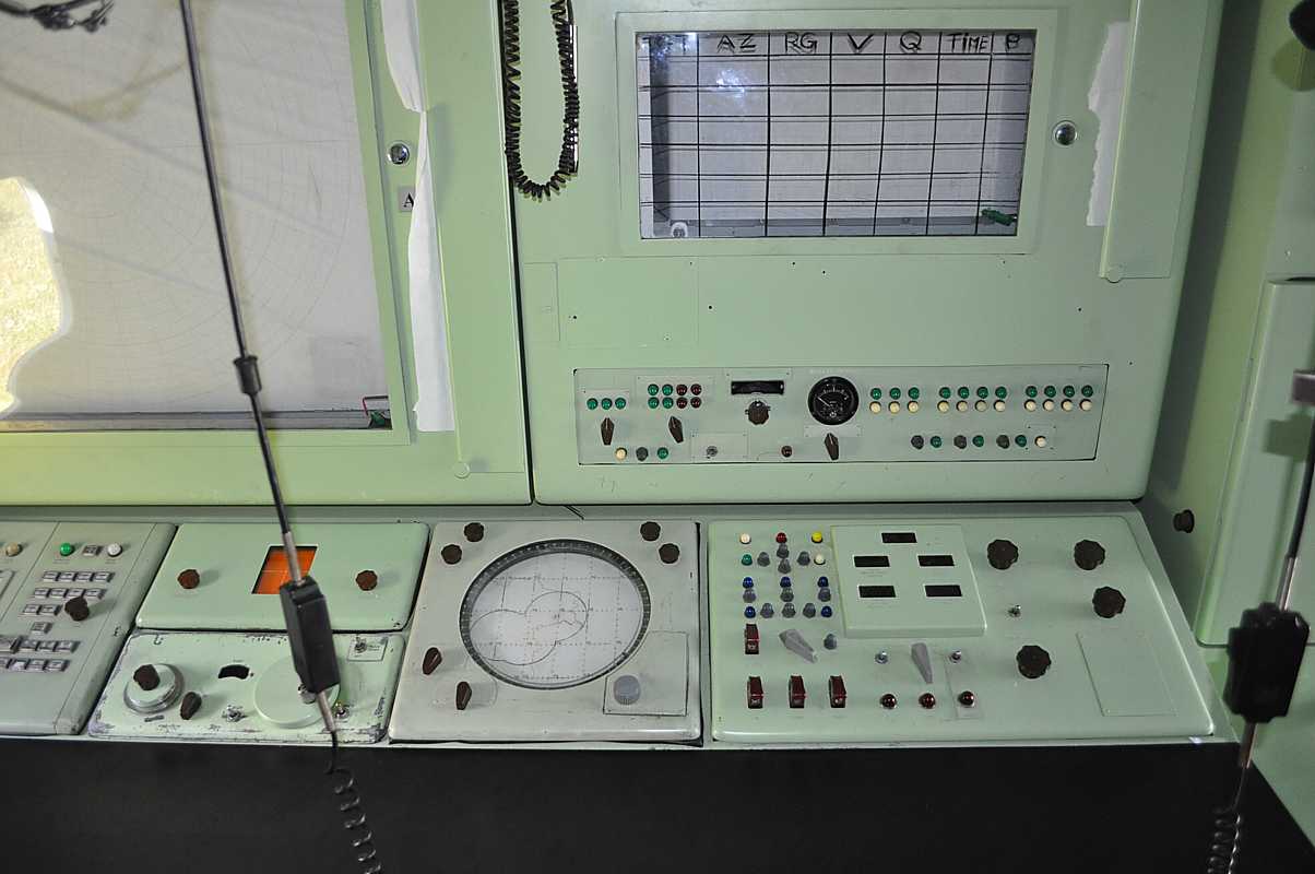
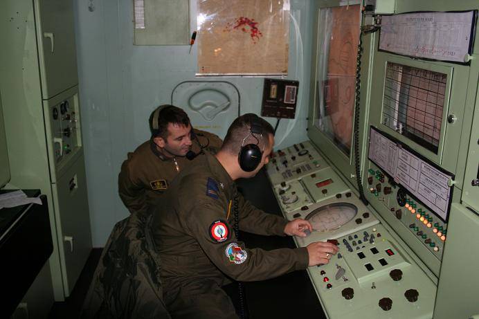
This is where the Battery Commander (or Battery Control Officer) and the Acquisition Operator sat. This was the central command place of the battery. Summations of the status of other places of the battery arrived here, and commands to battery components went out from here.
Visitors could view this area, but only after various charts and documents were covered, such as:
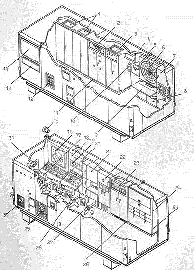
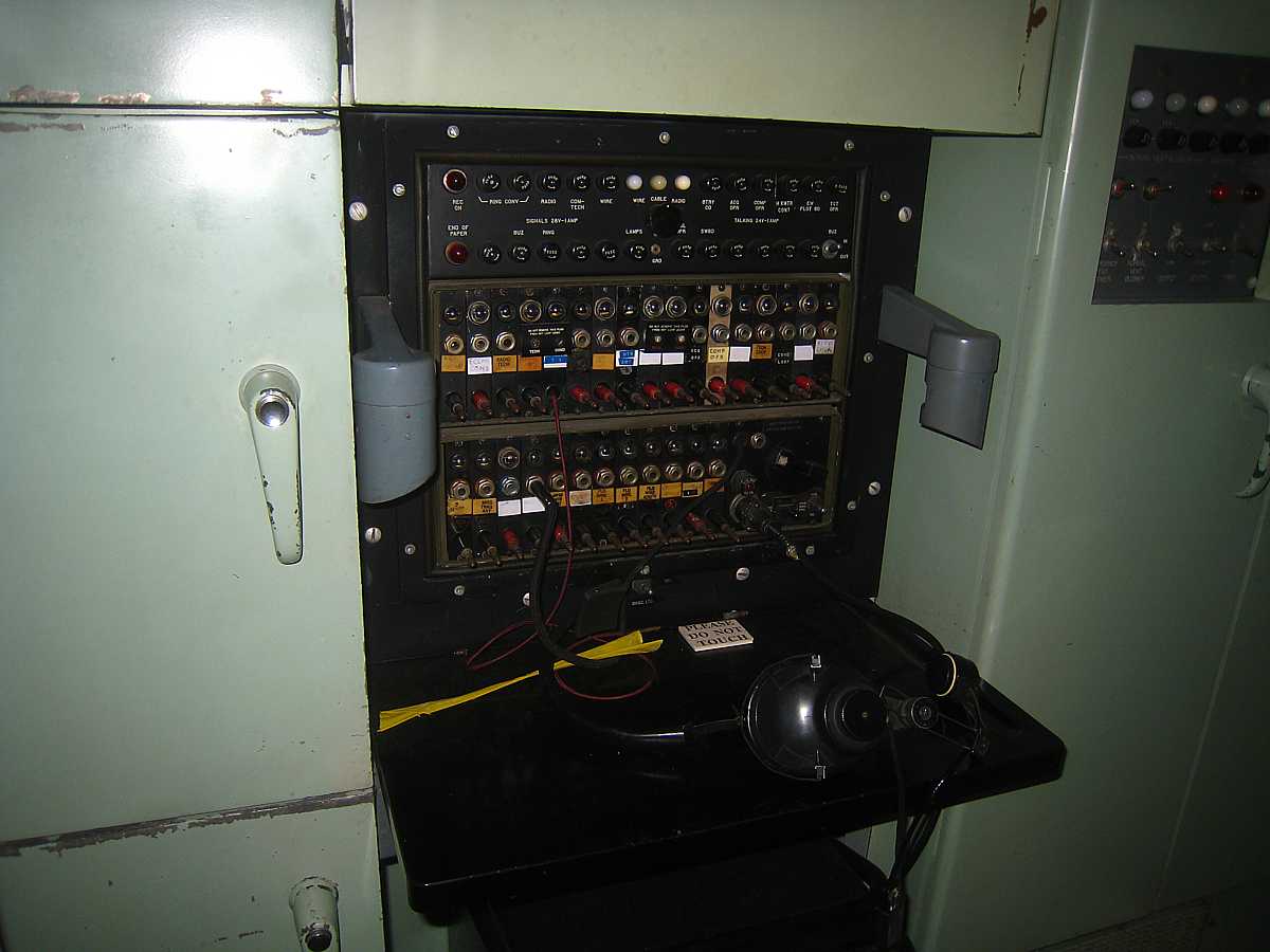
Expanded view of Battery Control Trailer John Porter, manager of SF-88, reports that "The Battery Control Van is 20.5 ft long, 8 ft wide, 7 ft high, with a 6.5 ft tongue." |
Left Side of BC van including computer and manual plotting board |
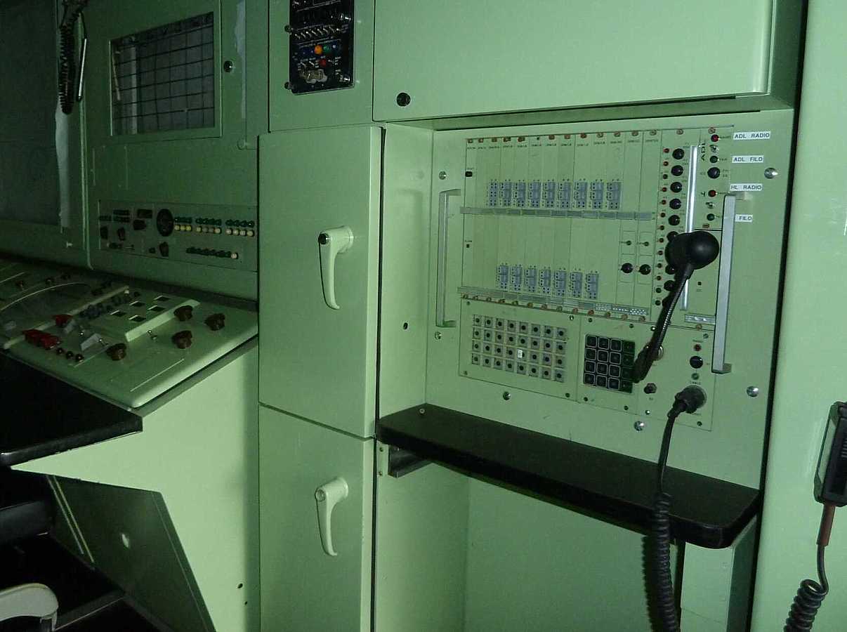
This is a diagram of the work place. The battery switchboard is just to the
right, and the computer cabinets are to the right rear.

Image from Rolf Goerigk
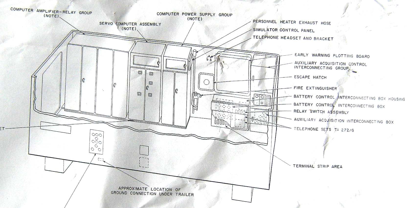
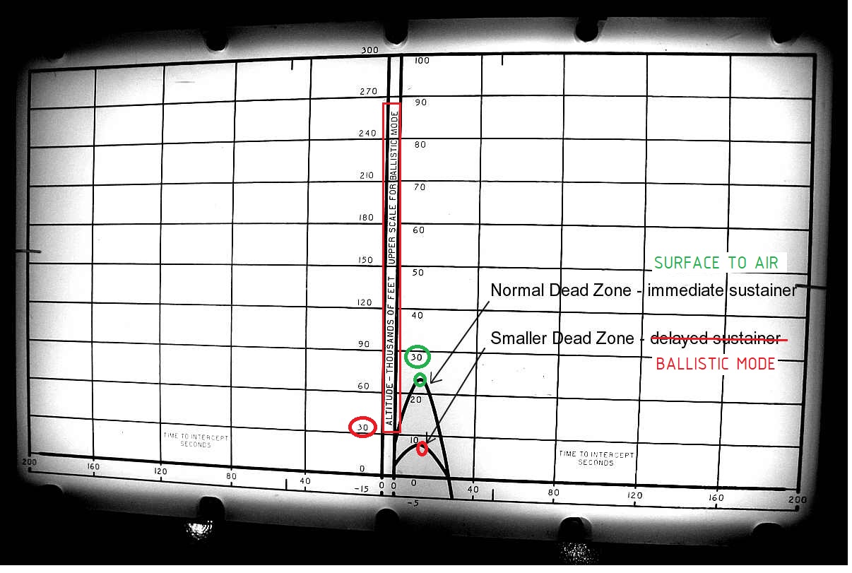
- Plotting board, thin paper & ink, largest ring is 200,000 yds (over 110 miles)
- T1 quick disconnect (T1 was a van that generated simulated aircraft echos and ECM interference for training purposes)
- IFF (Identification Friend or Foe) control panel (the latest version with the Siemens IFF/SIF) (more)
- ACQ control panel - control the LOPAR radar (more)
- HIPAR control panel - control the HIPAR radar (more))
- Precision Indicator (PI) - (expanded view of the PPI -about 22 degrees wide 10,000 yards long)
- also sent to the Target Tracking operators in the Radar Control van - Target Designator Panel - paints a ring and azimuth line to indicate designated target to Target Tracking operators
- Plan Position Indicator (PPI) ("radar scope") more
- Tactical control indicator (more)
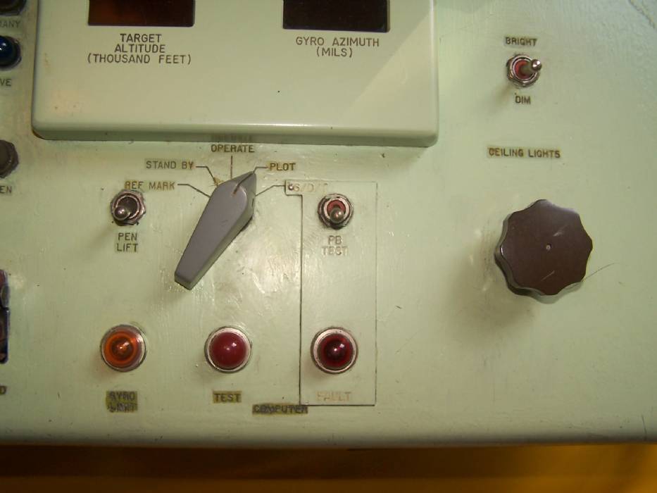
- BCC indicator panel (more)
- Vertical plotting board 200 kyds / 100 kft (more)
- Status indicator lights, (White, Yellow, Red, Blue)
- Target detected speaker (to help arouse sleepy operator)
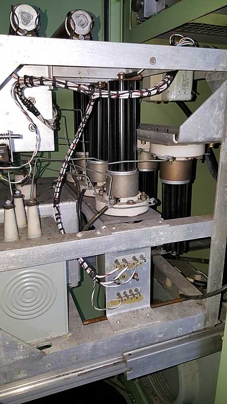
Plotting Equipment
Practical use of the above charting equipment is provided by the records of a Short Notice Annual Proficiency provided by Earl Close.
From Ted Willes
Part of the digital modernization (about 1980)
|


| LOPAR HV Rectifiers | 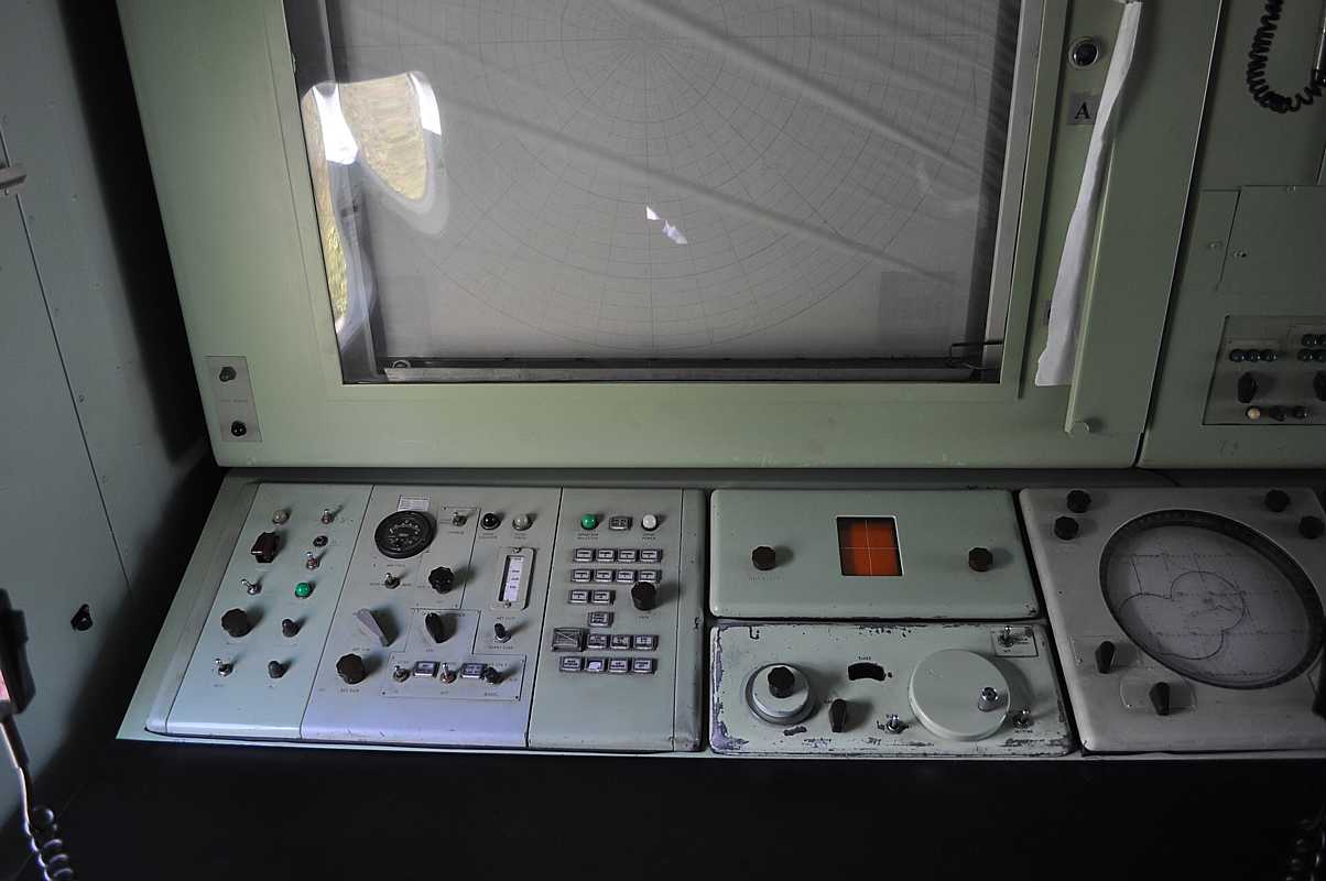
| BC Van Console Lopar Section |
| BC Van Console TCO & Comp Section | 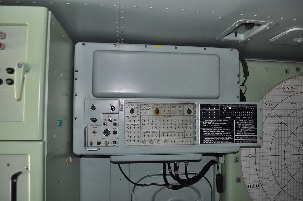
| BC Van BTE 77 |

| LOPAR HV Power Supply |

| plotting boards
in darkened BC Van normal in operation to better see the radar scopes |
Now for a little embarrassment - I forgot where I got these images, or who to give credit to -
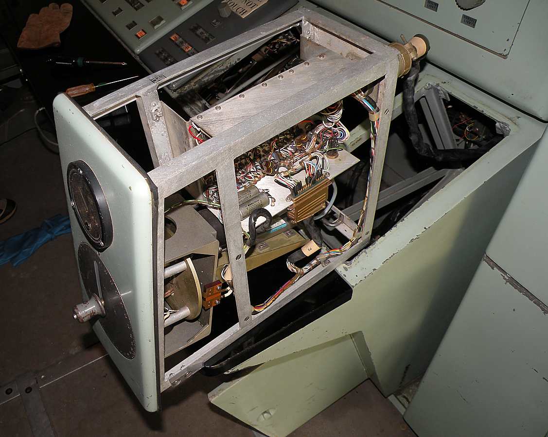
This is an upgrade modification from the Hercules equipment at SF-88.
| 
| 
| 
| 
|
More embarrasment - maybe confession is good for the soul, my soul.
I figured I was a hot shot on almost everything in the IFC - EXCEPT -
- All of the details of the big analog computer
which I figured nobody REALLY knew.
(I did as well as anyone in class) - The event recorder, which depended on the accuracy of tracking radars
if the radars were mis-aligned
the event recorder would never know !!
I refused to learn that fake, besides I had KP that day.
a blast from the past, December 21. 2013 Nike Ajax - Event Records Analysis all 2.4 MB as .pdf
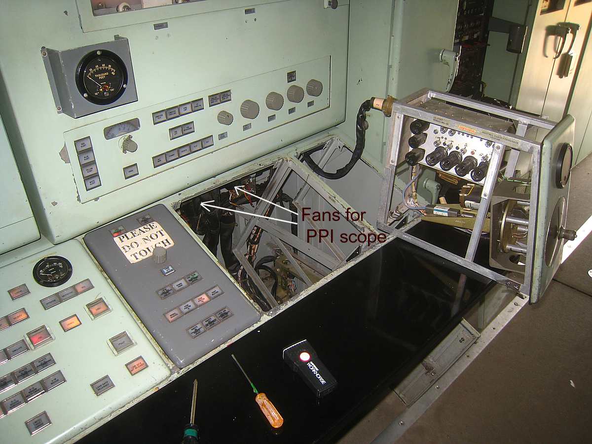
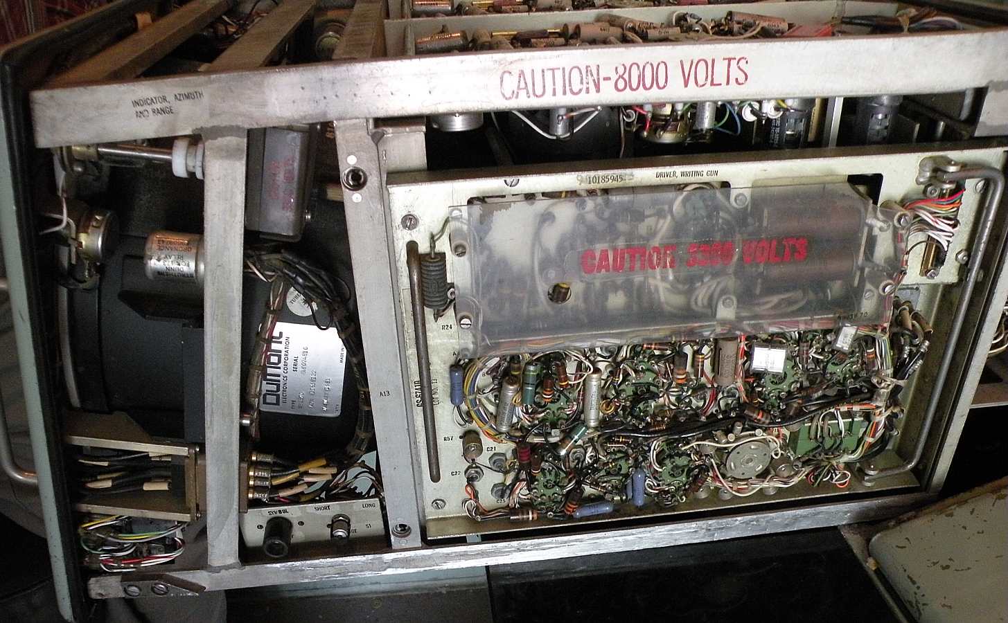
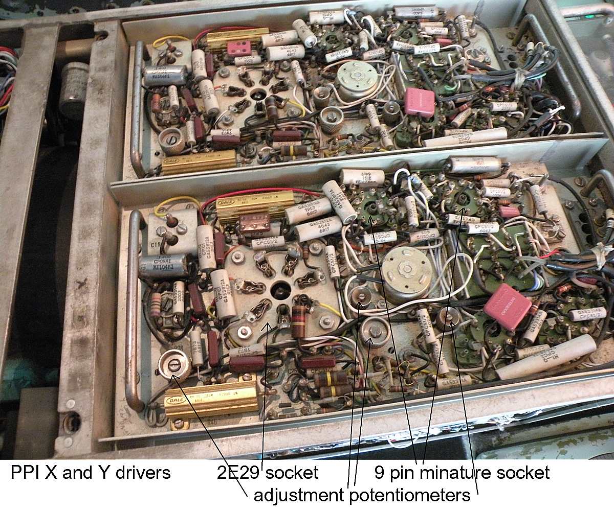
More Plan Position Indicator (PPI) ("radar scope"),
|
This is not a "study" of the PPI, just some more images taken during removal of fan noise from
a failed bearing.
Photos by Greg Brown, text by Ed Thelen
|

If you have comments or suggestions, Send e-mail to Ed Thelen
Return to home page, Goto Next Section
Return to beginning of Nike Radars
Updated Nov 12, 2017