Return to home
Goto Next Section
Please note: for a computer guidance perspective, please see
Missile guidance summary
This information is grouped into the following sections:
Also, for an actual flight path, see Intercept
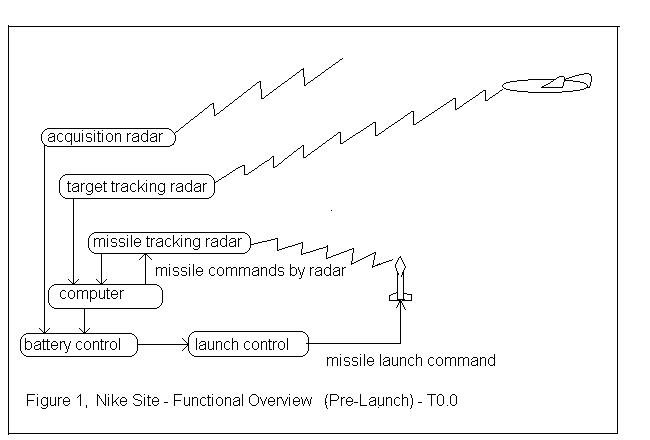
Time 0 sec, Electric Signal Ignites Booster
Time 3.4 sec, End of Booster, Start Roll then 7 g Dive
Quick discussion of "Dead Zone"
Determining when to end the 7 g dive
Time (approx.) 12 sec, End 7 g dive, start cruise
Time (later), Burst Command
--------------------------------
Preparing for the Next launch
Time 0 sec, Electric Signal Ignites Booster

The booster igniters (one for each of the four booster tubes) almost explode into large flames which ignites the main "cruciform" shaped solid propellant (potassium perchlorate and a rubber compound?). In just a tenth of a second, full thrust is attained and the missile starts to move upward at an acceleration of 25 times the acceleration of gravity. (The acceleration of gravity is about 32 feet per second per second)
The missile guidance is active, keeping the missile vertical (0 g's turning) and the bottom of the missile pointing in the same direction as at launch (no roll).
Time 3.4 sec, End of Booster, Start Roll then 7 g Dive
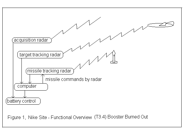
The roll maneuver is allowed one second to complete then the computer and missile radar command the missile to "dive" at 7 g's. This dive starts the missile toward the Predicted Intercept Point, since "down" for the vertical missile is in that direction.
The computer will continue sending this 7 g command until missile tracking shows that the missile is on a 0.5 g flight path to the Predicted Intercept Point. This path means that the missile will "fall" at an acceleration if 0.5 g s, and be supported by its fins by 0.5 g s (1/2 of the weight of the missile will be supported by the fins). This low weight on the fins decreases the missile drag, and the thin air of this high flight path will also decrease missile drag (keeping the speed high while decreasing the need for a larger sustainer motor).
The above paragraph means that 7 g dive is stopped a little early so the missile will make a shallow arc to the Predicted Intercept Point. If the Predicted Intercept Point is low and relatively near, the 7 g dive lasts longer. If the Predicted Intercept Point is high and relatively far, the 7 g dive lasts a shorted time.
Quick discussion of "Dead Zone"
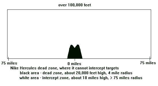
A method of decreasing the size of the dead zone is to cause the missile to go slower so that the turning radius is decreased. Delaying the start of the sustainer motor eliminates the normal missile speed increase during the 7 g (later 10 g) dive, decreasing the turning radius, and decreasing the size on the dead zone. This method is chosen when the predicted intercept point is close and low.
The minimum dead zone using this method is about 21,000 ft high and about 4 miles in radius.
If the predicted intercept point is more than 10 miles away, or above 30,000 feet, the firing of the sustainer motor is not delayed and the missile starts gaining speed to mach 3.5 earlier in its flight.
Nike sites were frequently patterned so that the dead zone of one site was in the firing or accessible zone of one or more other sites. Also Hawk batteries were sometimes placed near Nike sites as area defense (and they also defended the dead zone of a particular Nike site).
Determining when to end the 7 g dive
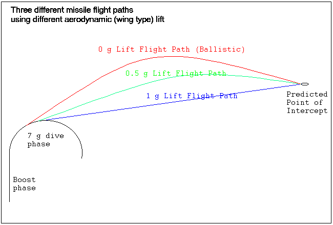
The "0 g" flight path is not supported by any air lift on the wings of the missile. The missile basically acts like a bullet, falling freely due to the acceleration of gravity. A person riding on the missile would not feel any gravity, would feel "weightless".
The computer determines when to end the 7 g dive to enter the 0.5 g path, ( this signal is called "On Trajectory" ) then steers the missile to follow this flight style.
Time (approx.) 12 sec, End 7 g dive, Start Cruise
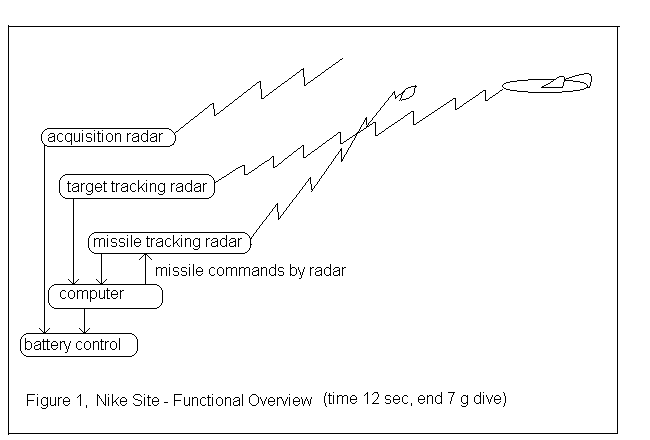
Steering commands are as gentle as possible until the last 10 seconds
to decrease steering caused drag,
and thereby maintaining highest possible speed.
( For details see
Computer Solving and
Computer Steering.)
The steering commands during the first part of the
normal flight are decreased to allow for the following effects:
Commanding the missile to steer hard for each wild change causes large g force commands, and the high "aerodynamic angle of attack" to produce the large g forces produce high drag. High drag reduces missile speed, causes longer flight time, and reduces range (all bad).
The reduced steering command scheme tends to average out the large swings, giving a faster flight. During the last 10 seconds of flight, full steering commands are sent.
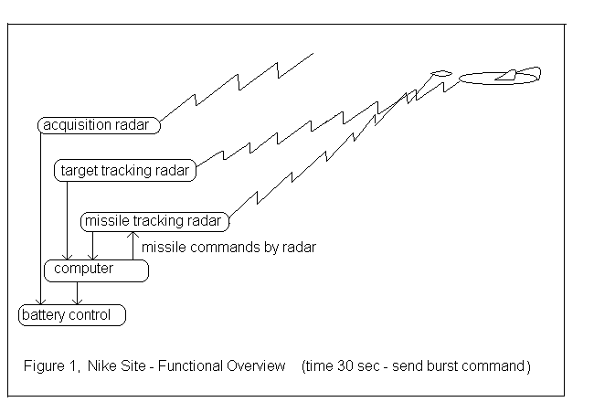
To help the battery commander to decide quickly if the target is disabled, there is a "Target Ground Speed" dial in front of him. If the target speed suddenly slows, and the target elevation suddenly drops, the battery commander may decide that the target has been disabled.
If the target appears disabled, a new target may be designated. This could be quite quick as there has been relative idle time during the missile flight for continued viewing and analysis of the defense area. Area control could well have designated the next target for this battery.
It will take the Target Tracking Radar maybe 10 seconds to slew to the next designated target, find the target in range and azimuth and elevation, and lock onto it. There is a PPI scope in the Radar control van showing the target tracking operators the same picture that the battery commander sees. This shows both the target and the azimuth and range of the TTR. This aids target acquisition in azimuth and range. The elevation operator has fewer aids. He may have been given advisories from the acquisition radars or area control about the height of the target, such as "appears high", "on the deck", but the target search in elevation has no real mechanical aid. He searches up and down quickly trying to find a target at the correct range.
The computer will take probably another 5 seconds to "settle" and give predicted intercept point, and the battery commander needs time to analyze the situation with this next target before committing a missile to it.
If you have comments or suggestions, Send e-mail to Ed Thelen
Updated April 7, 2013