Back to Home Page
These particular schematic diagrams describe circuits
in the IFC area. Similar diagrams described circuits
in the missile and launcher area.
The specialists (enlisted personnel and warrant officers) were taught the functions of each circuit and the general flow of signals and control in wonderful detail. (I thought I was in heaven.) The IFC people learned about 2 to 6 pages a day. I still remember the details (when looking at the schematics) after all these years. (And I have trouble remembering my social security number.)
The pages that I do not remember (upon looking at the schematics) were those taught while I was doing KP (kitchen police - helping in the kitchen!) (We thought the army was very short sighted in saving the few bucks having us "pull" KP while in technical school! Start of whine - "the Air Force technical school people don't pull KP".)
There were several hundred of these schematic diagrams for the IFC area, and probably somewhat fewer for the Launcher area.
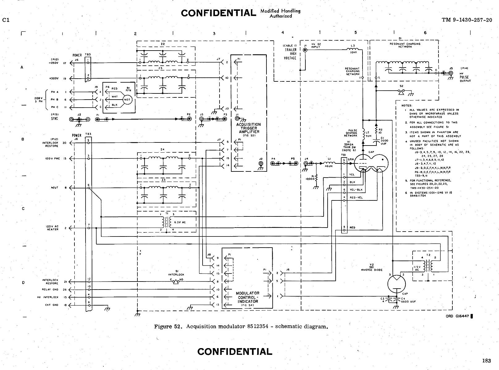
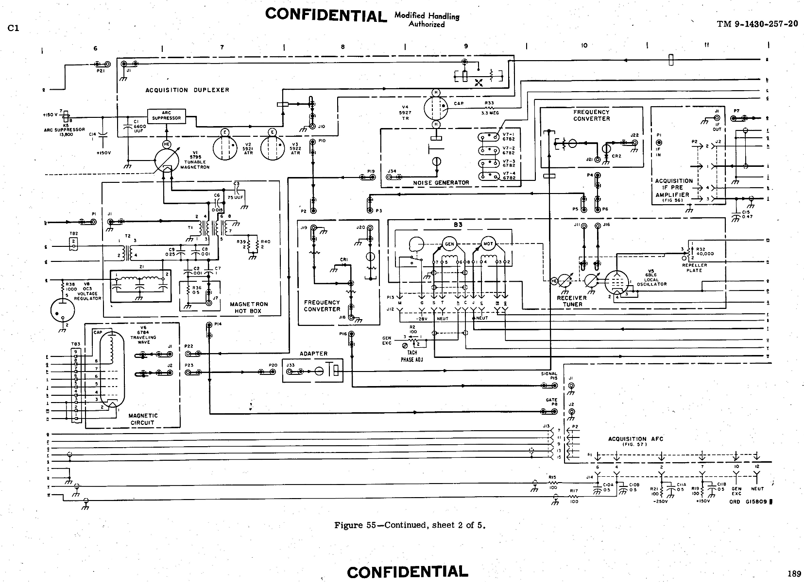
An interesting sample is the LOPAR radar modulator
and the LOPAR radar RF section.
Detailed operation can be found in
TM5000-9 Nike I -
Acquisition Radar Circuitry
| This modulator provides the powerful - 1 megawatt - pulses to the RF (Radio Frequency) section. 330 KBytes |
| This Radio Frequency section contains the magnatron, tuning, local oscillator, crystal mixer, into the IF (Intermediate Frequency) pre-amplifier. 420 KBytes |
|
Many of these precision DC amplifiers were used in the computer.

|
click blue box for expanded image (48 K bytes) There were 2 amplifiers per circuit. There were about 140 of these amplifiers in the computer, all identical except for external connections (signals coming in and signals going out). More details here |
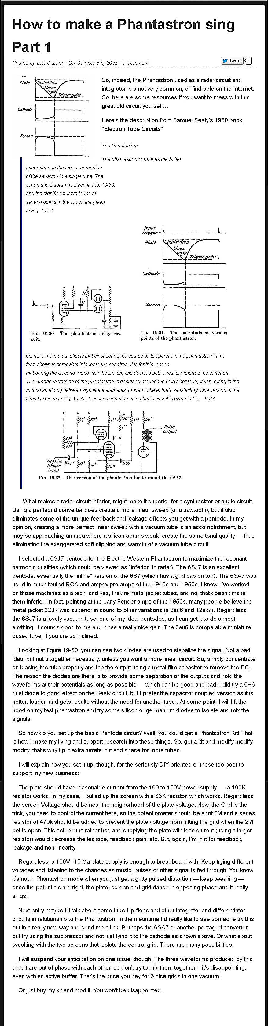
Track Range Unit Amplifier
- with Phantastron linear voltage to time delay circuit
This was used to help convert
- the time delay between the magnatron RF pulse and returned echo
- to a 0 to 100 volt "slant range" suitable for the analog computer
There was a 100 KHz crystal oscillator for calibration -
- shared between the target and missile range units for error cancelation.
|
click blue box for expanded image (72 K bytes) Logic to generate the range gate for display to the tracking operators and for gating the received signals into the servo system. Here is a web site with a semi-technical explaination. Local copy - 400 KBytes |
If you have comments or suggestions, Send e-mail to Ed Thelen
Back to Home Page
Updated May 5, 1997
Acquisition diagrams added Oct 2012