|
UNIVAC I
MAINTENANCE MANUAL
For Use With
Univac I Central Computer
Remington Rand Univac
DIVISION OF SPERRY RAND CORPORATION
NEW YORK 10, N. Y.
UNIVAC I
MAINTENANCE MANUAL
For
Univac I Central Computer Group
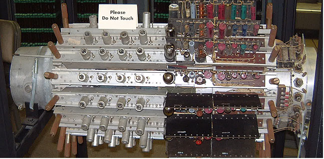
Physical Description
physical overview of Univac 1 note mercury memory
tanks INSIDE the computer. The UNIVAC 1 computer was a little room.
1-75. MEMORY SECTIONS
1-76. The principal internal storage in the Univac I system is
the 1000-word acoustic delay-line memory, consisting of 100
10-word mercury registers. Twelve additional 10-word
registers function as intermediate storage for input and
output; six more are spares. With modified circuitry, seven
more channels control the temperature of seven mercury
tanks, and one more channel is used for the 10-word Y-
register.
1-77. The total of 126 mercury channels is contained in the
seven mercury tanks mounted on the backs of sections MT,
MV, MX, NT, NV, NX, and GV. Each tank is divided into 18
channels.
1-78. Physically, each of the 10-word register circuits is made
up of three sections:
- The acoustic delay, consisting of a channel in a column of
mercury, with receiving and transmitting crystals mounted at
opposite ends.
- An intermediate-frequency (i-f) chassis, electrically
connected to the receiving crystal, and containing amplifiers,
a detector, and a compensating delay. The i-f chasses are
mounted on the shell of the mercury tank which they serve.
- A recirculation chassis, containing a cathode follower, a
pulse former and retimer, a modulator, which drives the
transmitting crystal, and input, clear, and memory-switch
gates. These chasses are mounted in the sections adjacent to
the mercury tanks.
1-79. All mercury channels except the 10-word Y-register
channel are identical, as are the recirculation amplifiers and
recirculation chasses of all 10-word memory registers and the
six spares. The recirculation chasses of the input register and
output register are slightly modified to enable use of control
signals different from those used in the main memory. The
10word Y-register mercury channel is shorter than the others,
and the recirculation chassis is different, since this register is
completely independent of the main memory controls. The
temperature-control chasses have the following modifications:
- In the amplifier (i-f) chassis the compensating delay is
removed (from V7) , and a dummy plug with dummy
connections is substituted.
- The bay-mounted chassis (chassis 2 in each memory
section) is not a recirculation chassis. The temperature-
controlling signal enters the mercury column from the cycling
unit each word time. At the bay-mounted chassis, this signal
is used to adjust the current through the heating coil to
maintain constant temperature in the tank. Each temperature-
control channel uses an entire bay-mounted chassis.
1-80. The interconnections among the three groups of
circuitry in a standard channel are shown in figure 1-18.
1-81. MEMORY TANKS. A memory tank consists of two
concentric cylinders. The inner tank is made of stainless steel
and contains the column of mercury that is used in common
by all the channels in the tank. The inner tank is 223/4 inches
long and 33/4 inches in diameter (figure 1-19).
1-82. Crystal-mounting plates are placed on the ends of the
inner tank. Eighteen transducing crystals are mounted in each
plate. One face of each crystal is in contact with the mercury.
The crystals are aligned so that each receiving crystal
receives acoustic waves from the corresponding, transmitting
crystal at the other end of the tank. To minimize crosstalk
between channels in the common mercury column, chrome
steel tubes are mounted between corresponding transmitting
and receiving crystals. These tubes act as waveguides.
1-83. Heating coils are wound around the outside of the inner
tank. The spare between the inner and outer tanks is filled
with insulating material.
1-84. The outer cylinder of the mercury tank is approximately
35 inches long and 81/2 inches in diameter. On this shell
(figure 1-20) are placed mounting brackets for the i-f chasses,
contact boards for the i-f chasses, input and output terminals,
and r-f filters for the heater circuits. Electrical connection to
the mercury tank is made by two cables, which terminate in 21-
pin male connectors. As seen from inside the computer, the
connector on the right (JP-2) carries automatic gain control
(AGC) monitor lines, and the one on the left (JP-1) carries the
power leads. On the opposite end of the tank from the contact
board is an overheat neon which lights if do is cut off because
of overheating of the tank on which it is mounted. On a
removable end-plate at the same end is a four-terminal barrier
strip for the overheat and standby power lines. Under the end-
plate are two adjusting screws for the microswitch stops and
the overheat neon.
1-85. Each long mercury tank has two heating systems, each
of which uses coils wrapped around the inner tank:
(1) Standby a-c heat; high power used to bring tank to
approximate operating temperature, coarsely controlled by the
contraction and expansion of the bellows which opens and
closes the standby microswitch.
(2) The d-c heat; low power used to maintain operating
temperature, accurately controlled by an electronic system.
1-86. The a-c standby heating system makes use of a 230-ohm
coil powered with 230 volts from phase 1, lines 8 and 9.
1-87. Current through the ac standby heating coil is controlled
mechanically by the expansion and contrac. tion of the
mercury in the tank. A port through the front crystal-
mounting plate allows the mercury to flow into an expansion
chamber. This chamber senses volumetric changes in the
mercury as the temperature varies. As the mercury expands, it
works a bellows which moves two microswitches against set-
screw stops. One microswitch controls the a-c standby
heating power, and the other is an emergency overheat cutoff.
When the expansion of the mercury indicates approximate
operating temperature, the microswitch contacts open and cut
off the a-c heat. Should the tank cool and the mercury
contract sufficiently, the contacts close and apply power to
the coil again. If the standby microswitch fails to shut off ac,
the tank continues to heat and the mercury continues to
expand. The bellows then operates the overheat switch. The
overheat switch cuts off a-c heat to all tanks, cuts off d-c
power to the computer, and lights the indicator neon on the
overheated tank. The tanks should be inspected immediately,
because after the tanks have cooled the overheat switch
closes again and the neon goes out.
1-88. A 3500-ohm coil provides d-c heat. This is the fine
temperature-control coil. The current through the coil is
adjusted by the temperature-control channel, which measures
the transit time of a pulse through the mercury.
1-89. The pulse is sent through the delay and then matched
against the sloping wavefront of a standard timing pulse. The
position of the delayed pulse on the standard pulse
determines whether the heat should be on or off. Just enough
power is supplied to the heating coil to balance the heat
dissipated from the tank.
1-90. MEMORY RECIRCULATION (I-F) AMPLIFIERS. The i-f
amplifiers are mounted directly on the mercury tanks (figure
1-20). There are 18 chasses mounted radially around each
tank. They are numbered counterclockwise from "three
o'clock" as seen from inside the computer. Chassis 14 of each
tank except tank GV is a spare and is on the bottom. (Tank GV
has no spare chassis.) With the exception of chassis 18, the
others are used as amplifiers in the recirculation path of one of
the information channels. Channel 18 is the temperature-
control channel.
1-91. The i-f chassis is built on the standard channel and has
standard mounts. One half of the chassis contains the
amplifiers; under this half of the chassis is a shield. The other
end of the chassis contains external component boards, the
compensating-delay stick and a 14-contact chassis terminal-
board. Tube positions are numbered Vl through V7 from the
amplifier end of the chassis.
1-92. The input point of the chassis is a spring-leaf contact
inside the shielded section just ahead of the Vl position. The
shielded section rests directly on the shell of the mercury
tank, and the spring-leaf contacts a special coaxial output
stub from the mercury channel. The signal goes through three
stages of amplifications in Vl, V2, and V3, which are controlled
by V6, the AGC tube. Tube V4 is also an amplifier. The tuning
slugs associated with Vl, V2, V3, and V4 are factory-adjusted
and require special equipment for setting. Tube V5 is a broad-
band video amplifier.
1-93. In the V7 position of the i-f amplifier is a plug-in
compensating delay unit. Because of uneven heat distribution
through the mercury, various channels have different delay
characteristics. Compensating delays equalize this difference.
The delay units are color-coded with a dot on the top of the
delay stick. Usually, these sticks are placed in the chassis as
shown in figure 1-21. Regardless of this layout, however,
whenever a chassis is replaced, the delay stick from the old
chassis or one of the same color should be used.
1-94. The output of the i-f amplifier chassis is taken from the
14-contact terminal board, which makes direct contact with a
female-contact terminal strip on the shell, from which the
signal lines run to the bay end of the tank. Terminal 7 on the
board is the memory-output terminal; terminal 11 is the AGC-monitor
output.
Figure 1-22. Recirculation Chassis
1-95. The line from pin 7 of the terminal board on the shell of
the tank carries the memory output as far
as a standoff post on the bay end of the tank. On the top of
this post is a pin. A jumper wire from the bay fits over the pin.
The jumper wire is soldered at the other end to a terminal on
the backboard of the bay and connects the output line to the
bay-mounted recirculation chassis.
1-96. All of the AGC lines from the contact boards on each
tank are bound into a cable and connected to the AGC-
monitor system by way of connector JP-2.
1-97. RECIRCULATION CHASSES. The recirculation chasses
of the memory are standard Univac I system chassis
(figure 1-22). They are located in chassis positions 3 to 10 of sections
GV, NT, NV, NX, MT, MV, and MX. Each chassis contains
two identical circuits, and serves two memory locations. Each
halfchassis has an address number, differing by 100 from the
other half. The only exceptions are locations M3X to M8X
and N5V to N8V. In both cases, the input and output registers
share recirculation chasses. For example, channel 1 of r0 and
channel 1 of rI share chassis M8X. In all memory sections,
chasses 1, 11, and 12 contain miscellaneous circuitry, such as
output whiffletrees, continuous wave buffers, and local drivers. In all
sections, chassis 2 serves memory channel 18, the
temperature-control channel.
1-98. On a recirculation chassis, tubes V 1 and V14 are
identical cathode followers; tubes V13, V12, and V11 make up
one pulse former and retimer; tubes V2, V3, and V4 make up
the identical circuit. Tubes V5 and V10 are the output
modulator tubes. Coaxial cables from terminals T63 and T79
respectively supply the continuous-wave signal from the cw
buffer-drivers to these two modulator tubes. Tubes V6 and V9
are normally conducting amplifiers; tubes V7 and V8 are input-
output control amplifiers.
1-99. Several components in the modulator stage are mounted
in a nonstandard manner. These parts are capacitors that form
an r-f-bypass network for the modulator. At operating
frequencies like 11.25 megacycles, it is advisable to keep leads
as short as possible. Consequently, the components are
mounted between connecting points on the base of the tube
instead of being put on the mounting boards. The parts so
mounted are identified by the initial letter, the tube
number, and one of the pins to which they are connected.
Thus R10-6 is a resistor connected to pin 6 of V10.
1-100. Information from the i-f amplifier enters the chassis on
backboard terminals T26 and T53. Terminals T26 and T53 are
connected directly to cathode followers V 1 and V 14. A
jumper wire with pinconnector is also connected to terminals
T53 and T26. These jumpers are video monitor lines. They
plug into pin jacks on the video monitor relay boxes mounted
on the framework next to the backboard.
1-101. Connection from the modulators to the memory tank is
made by means of short lengths of flexible coaxial cable
connected to backboard terminals T5 and T21. This cable is
terminated in a phono-pin connector, which mates with the
coaxial stub on the memory tank.
1-102. Timing pulses for the pulse formers and retimers, and
the continuous-wave signal for the modulator, are supplied by
local driver's and cw bufferdrivers located in the memory
sections. These signals are distributed to the chassis
backboards over a rigid coaxial line. The inner conductor of
this line is the sheathed inner conductor from a standard
coaxial cable. A piece of aluminum pipe mounted on standoff
posts, with a hole cut in its side over every chassis location,
takes the place of the outer conductor. The inner conductor
passes in and out of the pipe through the holes. Memory-
section backboard-layout drawings and distribution charts
supplied in the drawing file give details concerning the
connections for these signals.
Notes concerning the above manual:
- There were seven (7) mercury memories, not six as shown in diagram
"physical overview of Univac 1"
"1-77. The total of 126 mercury channels is contained in the seven
mercury tanks mounted on the backs of sections MT, MV, MX, NT, NV, NX, and GV.
Each tank is divided into 18 channels.
- On figure 1-18, there is an input "CW" to the modulator.
- This was 11.25 Megahertz as per figure 4.2 .
- The clockpulse was 2.25 Megahertz as per
figure 4.1 .
- So - a data bit time was 5 cycles of the 11.25 Megahertz carrier
- Each of the 12 decimal character per word had odd parity.
- This would allow a peak detecting AGC (Automatic Gain Control) of each channel to
work properly, and a "1" bit could have a known level different from a "0" bit.
- 100 channels of the 126 total channels were used for data.
As per 1-90 above:
- "Channel 18 [of each tank] is the temperature- control channel. "
- "Chassis 14 of each tank except tank GV is a spare and is on the bottom.
(Tank GV has no spare chassis.) "
As per 1-76 above
- "Twelve additional 10-word registers function as intermediate storage for
input and output; "
- "one more channel is used for the 10-word Y- register. "
That seems to be
126(total 10 word channels)
- - 7(temperature control)
- - 6(spare channels)
- - 12(input/output)
- - 1(10 word Y register)
= 100 10 word data channels giving 1000 words of program and data space
each word is 11 decimal digits plus sign and could contain 2 instructions
each decimal digit had 6 data bits and one odd parity bit
- Ballistic Research Labs REPORT NO. 971 1955 says that
the maximum latency is 400 microseconds,
- with a clock rate of 2.5 megahertz, (mentioned above)
that is 1000 clocks. This seems to indicate that there were 1000 bits in sequence
per channel.
- There is probably 1 bit in transit in the electronic chassis
(see figure 1-18) where there is the
- IF amplifier
- Detector, Video amplifier
- Plug-in delay
and the Recirculation Chassis with
- GC which looks like a clocked flipflop
- Modulator
so in fact there might be only 999 bits in the tank,
and one bit in the electronics ;-)
- Computer Structures Readings and Examples says that there were 12 seven bit characters
(6 bits plus odd parity) per word, and one 7 bit character time between words, used for
switching. That is 91 bit times (clock times) per word or 910 clock times per
ten word channel. Yes, I know - the numbers don't all exactly agree.
A probable cause is counting the sign character as part of the number
(the numbers were sign, magnitude, excess three coding).
|