|
Some manuals,
a CDC 6600 Brochure - 1963
Table of Contents
- Pac-Man Game
- a proposed 30 minute sub-tour of CHM
- What console games/experiences can you recall for the DD60 console, Aug 28, 2019
- Two-and-a half (2 1/2) Eye-Blinker stories for you, July 7,2019
- A slowed (intentionally) CDC-6400, the CDC-6300, - June 08, 2018
and many more
Pac-Man Game
|
The list of CDC / Cyber games on the site doesn't yet
list the console Pac-Man. This was written by a
Systems Programmer at Purdue University and distributed
for free.
I apologize that I can't remember the author's name.
It was a really good approximation of the "real" arcade
game. It ran in a PP. I know it ran on NOS version 2,
but can't be sure about the other CDC operating systems.
I think that I still have a 9-track tape with an OPL
file for Pac-Man and some other console games,
but no access to a tape drive. :)
Thanks,
Darrell Fluehr
Student at Michigan State Univerisy, 1976-1980, CDC 6500 + 6400, Extended Core Storage
+ later added Cyber 750
--- heavily modified SCOPE/HUSTLER operating system
Site Analyst at HDR, Omaha, Nebraska, Cyber 730, (they started with a CDC 6400, before I arrived)
--- NOS 2.x
Site Analyst at University of Nebraska/Lincoln, Cyber 815, 815, and 835
--- NOS 2.x, and one of the 815's ran PLATO Computer based education
|
a proposed 30 minute sub-tour of CHM
|
Seymour Cray and the Supercomputer
Jay McCauley, 408 926 2312, mccauley3@sbcglobal.net
This 30 min. tour highlights the CHM collection of "supercomputers" with emphasis on the
man responsible for many of them, Seymour Cray.
What are "supercomputers"? Term from 1960-1990�s for very big/expensive machines designed
to compute the hardest problems, e.g. nuclear weapons simulations, computational fluid dynamics (CFD),
computational chemistry (CompChem), numerical weather prediction� These problems could not be
economically solved on smaller systems, or had real-time requirements, e.g. weather prediction. Later,
auto crash simulations, biological projects (genome analysis), chess (spare time�), prime number search
(spare time).
1. IBM 7030 "Stretch", �our most successful failure.� Scene setting
for the forces driving big computers in the �50s (AEC, DoD, intel). Ego competition btw LASL & LLL.
Contract w/ LASL (check date) 100x IBM 704/9. Transistors vs. tubes give 20x, not nearly enough.
Architectural innovation [elided from most tours: pipelining, branch prediction, pre-fetch, speculative
execution, write buffer�]. Alas, not enough to meet contract requirements, only 60x-80x, IBM must reduce
price below cost of manufacture. Withdrawn from the market after only 9(?) units shipped. Still, team
members go on to play key roles in S/360.
2. CDC 6600. Introduce Seymour Cray w/ NTDS, as one of his design signatures, small,
simple PC cards. (Optional for deeper tours: Introduce Little Character & CDC 160, then the
CDC 6600. 6600 has 160 CPU as a Peripheral Processor, used in a sophisticated way to fetch/store data
from memory, allowing main processor to run faster.) Superscalar architecture (multiple functional units),
need a good analogy� ~3x STRETCH performance. Introduce rat�s nest of wires and refrigeration units,
cordwood module.
Tell story of Watson memo and the suit and pre-trial database:
Last week Control Data... announced the 6600 system. I understand that in the laboratory developing
the system there were only 34 people including the janitor. Of these, 14 are engineers and 4 are programmers.
Contrasting this modest effort with our vast development activities, I fail to understand why we have lost our
industry leadership position by letting someone else offer the world's most powerful computer
. � Thomas J. Watson, Jr.
It seems like Mr. Watson has answered his own question. � Seymour Cray
Partly in response to the Watson memo, IBM announces the 360/91 and markets it aggressively against the
6600. CDC files suit (restraint of trade?), and builds an extensive database of pre-trial disclosure materials.
One of these turns out to be a memo from the 360/91 manager to the 360 Launch marketing team (parphrasing)
"I understand that you intend to announce the /91 on launch day. We don�t think that�s a good idea, as
we haven�t even picked the logic family for it." Smoking gun. IBM settles the suit, gives CDC a
substantial amount of $ and the Service Bureau Corporation, and asks only that the DB be destroyed. IBM
was also engaged in a Federal Antitrust suit, and the DB could be very harmful to their case.
3. CDC 7600, yet again the fastest machine in the world. Approximately 3-5x 6600, with maximum
performance 30x. Basically the same high level architecture as the 6600, but uses pipelining to boost
peak performance. Unreliable, poor up times initially.
Cray leaves CDC and founds Cray Research. CDC is an initial investor.
4. CRAY-1.Vector processor. Point at Chippewa Falls pictures in hallway as long as they are still
around. New physical layout. World�s most expensive love seat, but don�t sit there, 12,000A @ 5V = 60 KW,
what goes in must come out� Built using Fairchild ECL IC�s and RAM. I wish we had a card like the
cordwood module.
5. CRAY-2, Fluorinert cooling. Bubbly, mad scientist cooling unit. Point out almost nobody every
saw these machines except for operations staff.
6. Cray X-MP and Y-MP. First multiprocessor machines. X-MP is a Steve Chen machine,
direct competitor to Cray-2, somewhat more successful.
Cray leaves Cray Research, founds Cray Computer Corp. in Boulder, CO.
[Silicon Graphics buys Cray Research, spits it out in a huge loss a few years later. Cray Research is
bought by Tetra Computers and renames itself Cray Research. SGI still exists, a shadow of its former self.]
7. CCC Cray 3. GaAs implementation. Only one complete machine built, delivered to NCAR on loan.
Artifact is a processor brick. 1-16 bricks in a machine (NCAR has 4). Cray�s death in car accident, 1996.
Forces drawing supercomputer era to a close:
- End of Cold War funding
- New ideas on how to attack hard problems (possible tie to Illiac 4 as prototype for massively
parallel processors). Current champ "Blue Gene" at Livermore, 131,000 Power PC2 processors,
same "family tree" as Deep Blue, the chess machine.
Additional notes
This tour has been given several times, and has been well received and is almost exactly
30 min. I�d like to keep Stretch in the tour as it sets the scene (and you walk right by it going to the
6600) and leads to the Watson memo, and Cray�s reaction, which speaks to Cray�s style. I think almost any
of the docents could give this, we routinely cover the supercomputer row.
In a back of the envelope calculation, the CDC6600 is roughly as powerful a computer as an iPOD! It�s
a 10 MHz clock, but gets things done in four phases, so is effectively a 40 MHz, 60 bit machine. An iPOD
contains two 75 MHz 32 bit ARM processors. So easily in the same ballpark as the 6600.
I�ve avoided some of the "legends" about Cray, as I believe many of them to be apocryphal.
This is probably worth a bit of research, but one has to be careful to get close to original sources,
these legends take on a life of their own and get cited as if they were true.
|
Looking for information.
What console games/experiences can you recall for the DD60 console
from Richard Ragan Aug 28, 2019
Looking for information. What console games/experiences can you recall for the DD60 console.
Here is a starter list I can recall:
- Baseball
- Andy Capp
- Snoopy
- Lunar Lander
- Worms
I think these were all part of the CE test tape SMM?
Does anyone still have the source of any of these? Or binaries like in the grand old
Chippewa 0.9 days with comments like "decompiled from the binary by xxxxxxxl
Ed Thelen comments "There was also a very good chess program,
out of NorthWestern University if I remember correctly.
I saw a guy (David Sweet) beat it, but he needed one take-back ;-)
That program needed a DD60 PP driver to portray the chess board :-)
|
Two-and-a half (2 1/2) Eye-Blinker stories for you
from David Adcock July 7,2019
|
I first enrolled at UT-Austin in Fall 1966, and the UT Computation Center was just bringing online
the new 6600. (Rumor had it at the time that the UT 6600 was the first one that ACTUALLY WORKED
at a customer site! Los Alamos(?) and one other facility had purchased a 6600, but both of these
systems were having stability problems�)
The UT 6600 was purchased largely at the behest of Prof. F. A. Matsen (Physics & Chemistry) and
Prof. M. J. S. Dewar (Chemistry), both of whom used considerable amounts of computer time for their research.
(STORY 1) In the Spring semester of 1968, I was working for Prof. Matsen as a grader/programmer. During the Spring semester of �68, the Comp Center administrators decided to shut down the 6600 over the last weekend of Spring Break - it was SO FAST that it would sit largely idle over the weekend. At the time, the UT Comp Center was a Training Center for CDC Customer Engineers. Fortunately (for UT), it was a CDC Customer Engineer trainee who �shut down� the machine. Alas, he only shut off the chilled water cooling system, but NOT Logic Power! When the Comp Center staff returned the next Monday morning, the central �X� cabinet had become so hot that the plastic �Control Data Corporation / 6600� sign had melted and run down the side of the panel! SURPRISE - Nothing Worked! As I recall, ALL memory had to be replaced, as well as the boards containing the arithmetic units, followed by other boards too. It was MONTHS before it was running well again: Up for an hour, then down for 2 days, then up for 2 hours, then down for the rest of the day, etc., etc. Some of the Matsen group could not finish their research work, and had to finish their MA / Defense by one or two semesters later.
(Intermediate Story) The UT Comp Center ran SCOPE until about 1968, when the UT Comp Center staff designed a new O/S for the 6600 - UT1, and later UT2-D (mainly designed by John Howard). UT2-D incorporated the 6600 plus a CDC Extended Core Storage (�ECS�) unit. When UT purchased a 6400 to be the �interactive timeshare computer�, it seamlessly integrated into UT2-D.
(STORY 2) I returned to UT in Fall 1994 as an �Older Than Average� Grad Student - in Physical/Theoretical Chem. My Advisor was Prof. Robert E. Wyatt, and mounted on his office wall was one of the Original Platters of the CDC 808 disks from the original 1966 CDC 6600 system! It was about 3.5� in diameter! A bit of computation determined that it had held a bit over 4 (FOUR!) Mb.
Thanks for keeping Old Time Computing alive!
Dave
---
Dr. J. David Adcock
Lone Star Biotechnologies
www.lonestarbio.com
|
A slowed (intentionally) CDC-6400, the CDC-6300
from David Shillito - June 08, 2018
At the beginning of my career I worked for Control Data Australia from late 1972 to the end of 1974.
I was employed in the Sydney Cybernet Centre where we provided batch
processing to a range of customers on a CDC 6600.
I was in the team that looked after the SCOPE operating system,
applying updates from the USA and integrating them with our local changes.
I left after 2 years to go into developing minicomputer software for
applications such as ambulance despatch or airport information displays.
I am now retired but in my final job I was developing apps for iPads and for Android phones.
I noted that part of your activities in 1971 involved gong to the customer site,
installing the system and supervising the acceptance tests so I thought I would relate
an anecdote from my experience that relates to acceptance tests.
In 1974 Control Data had sold a CDC 6300 system to the Queensland State Government
Insurance Organization (SGIO). The customer required that we prove the performance of
each instruction in the CP and PP instruction sets. If the manual said the XYZ
instruction took 3 clock cycles (300 nanoseconds) then that is what I had to prove.
I was adept at assembly language programming so I had no trouble in creating a set
of programs that did what the customer wanted. But when I went to the site in
Brisbane to run the tests on the customer�s own system I found that they ran too fast.
It seemed that all (or an important subset, I cannot remember after 44 years)
took 3 clock cycles fewer than they were supposed to. It was eventually determined
that the only difference between a CDC 6300 and its more expensive but faster
sibling the CDC 6400 was a card in the former than had the effect of adding a
3 clock cycle delay to each instruction. It seemed that wrong card had been
inadvertently left in the system that was shipped. I expect the situation was
rectified and the tests rerun so the customer got only what they had paid for.
Perhaps they were even persuaded after a few years to upgrade to a CDC 6400
at a considerable cost and the card could have been replaced.
|
Power, from cctech-request@classiccmp.org with Paul Koning - 2/19/2018
Looking at CDC 6600 CPU cabinet power schematics, you can see 400 Hz 3 phase powering the DC supplies, and 50/60 Hz three phase for the cooling system compressors. An interesting detail is that the DC supplies seem to be unregulated, with choke input filters. That makes some sense, the load is reasonably constant with the logic used in the 6600, and choke input supplies have decent regulation.
The DD60 console takes 400 Hz 3 phase for the high voltage supply, and uses 60 Hz single phase (120 volt) for the other supplies.
|
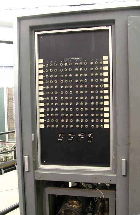
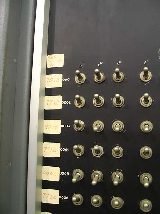
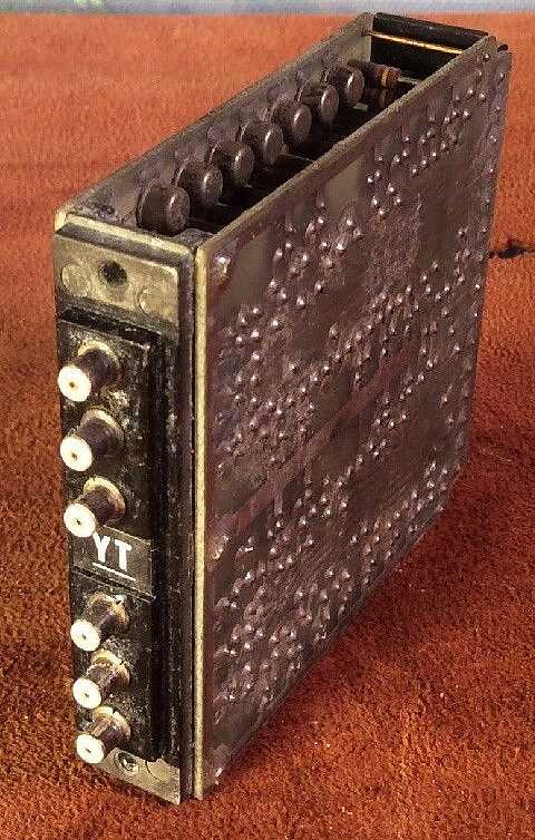
Just for fun, the Dead Start panel
For reasons unknown, the browsers
FireFox and Chrome flip the expanded views sideways :-((
Oddly, "Best viewed with Internet Explorer".
I never thought I would say that ;-))
|
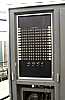
overview
|
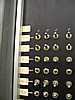
detail
|
> Message: 20
> Date: Sat, 8 Mar 2008 21:18:32 -0800
> From: "Rick Bensene" rickb@bensene.com
> cctalk@classiccmp.org
...


>
> The displays on the console were driven by a PPU (Peripheral Processing
> Unit), which were small scalar processors (actually, one processor
> multiplexed to appear as a number of independent CPUs), akin to small
> minicomputers (like a PDP-8), which operated out of shared sections of
> main memory.  There was a PPU program that ran the display, generating
> it from data in a section of memory.

In SCOPE, PP # 10 was dedicated to this purpose -

Each time shared PP (using a common adder) had its own memory of
4 K 12 bit words.  This reduced the traffic to main memory.

PP # 1 was normally assigned to monitor requests from the jobs
   assigned to "control points".  A job would place a request in
   its relative memory location 0 for service by the system.
   PP # 1 would monitor these requests and assign other
    PPs to do the work, causing a PP to load a new program
     if  necessary.


I worked in CDC Special Systems from 1966 to 1971 -
    We shipped a version of SCOPE modified to run "Time Critical"
     which used modified code in PP #1 to guarantee user choice of
           - analog and discrete inputs
           - x milliseconds CPU time
           - analog and discrete output
        on a guaranteed time cycle -
    This was the best in the world at the time for doing hybrid computing :-))
         which unfortunately was on its way out :-((
    A system program to calculate resources to see if
          a new "time critical" user could be added to the running list.

>  The displays were vector only, not  raster.

Yes :-))

> There was dedicated hardware in the display console that did
> CDC character set (a 6-bit code) conversion to vector characters.

Not in any system we shipped, and we could run the "EYE"
   and Northwestern University CHESS program with
        another PP displaying the chess pieces in nice form
        on the right hand scope.
   The left hand scope being assigned to monitoring
     activity at the normally 8 "control points",
        showing activity and requests for operator intervention
        such as mounting/removing tapes and printer(s) out of paper...

> Vector graphics were possible, within the limitations of the speed of
> the PPU.

Each PP had a 100 nano-second time sharing of the adder each 1 microsecond -
    hence a relatively hard upper limit of 10 PPs with out a special
    order for another 10 ( for customers such as Boeing).

On later 6x00-series systems, such as the CYBER-73, the PPUs
> ran fast enough to generate a nice looking all-vector chessboard on the
> left screen, and a text-based transcript of the moves on the right
> screen.  There were also a number of other cute programs, one being a
> pair of eyes (one on each screen) which would look around and blink.
> The operating system was called KRONOS, and I clearly remember that the
> console command to run the "eye" program was "X.EYES".

Greg R. Mansfield had KRONOS going, and shipping to some customers,
      - mostly educational - by the time I left.
  Greg  was kind of a one man band - a bit of a Dilbert
     - a remarkably imaginative and productive individual -

I left CDC long before the CYBER-73
....
>
> Rick Bensene
> The Old Calculator Museum
> http://oldcalculatormuseum.com

Ed Thelen
|
CDC Cyber Emulator -
spotted by Jim Seay
Tom Hunter
reported in December 2002 to the following Newsgroups: comp.sys.cdc, alt.folklore.computers
> Here is a Christmas present for you: CDC Cyber mainframes are back!
>
> The just released Desktop Cyber Emulator version 1.0 emulates a
> typical CDC Cyber mainframe and peripherals. This release contains
> sources for the emulator and tools, as well as binaries compiled for
> Win98/NT on Intel/AMD PCs. You can download the release from
> "http://members.iinet.net.au/~tom-hunter/"
     (New e-mail and web address)
>
> The emulator runs the included Chippewa OS tape image (handcoded in
> octal by Seymour Cray).
>
And emulates a CDC 6600 with 10 PPUs, 1 CPU, 256 kWord
memory, 40 channels and the following devices:
- Console,
- disk drives (6603, 844),
- tape drives (607, 669),
- card reader (405),
- line printer (1612)
- and -
Has anyone still got Control Data Cyber deadstart tapes and possibly
matching source tapes? The following would be of great interest for
the Desktop Cyber Emulator project. These tapes deteriorate over time
and if we don't preserve them now they will be lost forever. Even
Syntegra (Control Data's successor) have no longer got copies of MACE,
KRONOS and SCOPE.
The following deadstart and source tapes would be great to salvage:
- MACE 5
- SCOPE (any version)
- KRONOS (any version)
- NOS 1
- SMM diagnostics
An SMM deadstart tape with matching source would help in fixing the
remaining problems in the emulator.
I can supply a small C program (in source) which will read those tapes
on a UNIX or VMS system and create an image which can be used to
recreate the original tape (fully preserving the physical record
structure and even tape marks).
- - - - - -
Richard Ragan of Syntegra is quoted as
"I can verify that it works and have booted up the Chippewa OS. Ah, those old green screens
again. Watching the Dayfile, the B-display and looking at the control points on the D-display in octal. Takes you back.... "
There is a popular scientific benchmark called the Linpack Benchmark used to
measure the speed that a particular computer can complete a particular "compute bound"
task. As per
Linpack Benchmark
Jim Humberd suggests here "
that IBM �invented� the 7040/7094 - DCS (Directly Coupled System), in response to my efforts
to sell a CDC 6600 to one of IBM�s largest customers. ... The CDC 6600 consisted of a large
central processor, surrounded by 10 peripheral and control processors that were assigned the
tasks of operating the devices connected to the input/output channels, and transferring data
to and from the central processor.
"That idea was so compelling, IBM came up with the idea of the 7040/7094 - DCS, later upgraded
to a 7044/7094 - DCS as their answer to the CDC 6600. "
|
PROCEEDINGS OF THE IEEE, VOL. 76, NO. 10, OCTOBER 1988
(starting on page 1292)
|
F. A 1960 Supercomputer Design and a Missile Using Silicon Planar Transistors
Two of the first silicon bipolar n-p-n transistor products
should go into the historical record book, not only for the
enormous profits they generated which enabled Fairchild
Semiconductor Laboratory to greatly increase its research
and development efforts that led to the rapid introduction
of whole families of volume produced silicon transistors
and integrated circuits, but also for setting the pace on computer
system designs based on the availability of certain
superior transistor performance characteristics, such as
speed and especially reliability.
The origin of the first product was the gold-doped high-peed (16 ns)
switching n-p-n transistor, 2N706. It was a
smaller mesa (three-times smaller diameter at 5-mil or an
area of 1.2 x 10⁻⁴cm2) and higher speed version of the 2N696
bipolar silicon n-p-n discussed in Section IV-D which had
been marketed by Fairchild in 1960. Gold is a highly efficient
recombination center for electrons and holes. In order to
increase the switching speed, gold was diffused into the
transistor to reduce the minority carrier lifetime and thus
the charge storage time in the base and collector layers of
the 2N706.
Based on this existence proof, Control Data Corporation
awarded Fairchild Semiconductor Laboratory a
$500,000 development contract to produce a still higher
speed silicon transistor switch to meet the first requirement ----
the high switching speed (less than three nano-seconds) of the
10-MHz (3MIPS) CDC-6600 scientific computer [69].
The second requirement was reliability since
there were 600,000 transistors in the CPU. That contract was
followed up by a $5M production contract for 10 milwidth=90%
units of high speed, gold-diffused, transistors and 2.5 million
units of high speed, gold-diffused, diodes in September 1964.
In fact, the transistor specifications of 3-ns and
high reliability were arrived at by the CDC computer
designers based on the required speed and reliability to
complete a numerical solution of a scientific problem without
interruption from a computer hardware failure [69].
In order to achieve several thousand hours of CPU run-time
without failure, high reliability from the individual silicon
planar transistors was the most critical consideration owing
to the large number of transistors (600,000) used in the CPU
of the CDC-6600. Noyce's monolithic technology has greatly
improved the numerics of reliability today.
For example,
the 600,000 transistors in CDC-6600 is only about one-half
of the number of transistors contained in a 1-mega-bit(Mbit)
DRAM chip which has a projected chip operating life of 10
years and as many as nine or more 1-Mbit chips can be used
in a single personal computer today which rarely experiences
MOS memory failures and whose failures are usually
due to the crash of the mechanical magnetic disk drive.
To
meet both the 3-ns and high-reliability specifications, Fairchild
engineers shrunk the circular 16-ns mesa 2N706 transistor down
to a three-finger stripe geometry and used oxide
passivation for stabilization. They also improved the yield
by using an epitaxial layer to control the resistivity. The
result was the 2N709 which met the 3-ns switching time and
high reliability requirements. It gave a 2000 CPU-hour operating
time before a transistor fails.
This was a very large
development and production contract for the design and
delivery of only one transistor type-by comparison, it took
only about $250 000 to start a silicon transistor manufacturing
company in 1960. High speed and high reliability of
the 2N709 met the critical requirements that made the first
scientific computer possible.
....
|
from Ed Thelen ----------------------
When I was hired by Control Data, Special Systems,
   a group of us were given a one month familiarization
   on the CDC 6600 so that we could indeed take advantage
      of its special features for the Special Systems Division.  :-))

Early in the class we discussed the lack of a
      HALT instruction
      HALT and  SingleStep switch
in the 6600 -
There was actually no way to stop the main computer,
    with out pulling power, it was always running something -
      it could be executing garbage, but it was running!

(I should explain, there was an
      - address base register, "Relative Address" or RA register
            the processor treated treated this as address 0
            and could not execute or store below this address
      - field length register, FL
            the processor could access memory between
                 RA and RA+FL
The operating system, usually focused in Peripheral Processor 0, PP0
    could control this and other registers
    using the Exchange Jump instruction in a PP.
    http://ed-thelen.org/comp-hist/CDC-6600-R-M.html#TOC/       )

Like how are you going to debug step by step with out a
    HALT instruction?
    HALT switch?

It turns out you must do it a different way -
   "WHY"
   "OK, so you halt,
        a)  no internal registers are available
                    on any expensive light panel -
        b) no switches are available to change anything
     and besides,
        a) who wants to halt a $6,000,000 machine
              and sit at the console pondering?

The single step debug method was to replace the following
  instruction with an
         ExchangeJump
instruction, which
      a) dumps the machine registers into memory
      b) starts to execute the next program
and you use a PP (one of 10) to examine the
   dumped registers and memory area of the
   interrupted program.

That way, you can do instruction by instruction debug,
   while running the machine (productively) at almost full speed.

And besides, a HALT instruction in a pipelined machine
    requires lots of messy, slow logic.

So, Console Step by step debugging, if you REALLY need it requires,
    a) 1/2 of the dual CRT console
    b) one of the 10 Peripheral Processors  (PPs)
    c) the memory required by  the program,
         (which can be swapped to disk
                 while you are scratching your head)

In my 5 years with Control Data Special Systems,
     doing really unusual time-critical systems programs,
     including modifying PP code,
  I never had to resort to Console Debugging -
        enough other aids were available :-))

In so many ways Cray was way ahead
        of the rest of the world.
 And then he came up with the beautifly designed and sublime
    CRAY 1
  Picky people might suggest that his associate, Les Davis
picked up, fixed up lots of rough edges in the orignal designs,
but then again, Seymour could then go roaring off
to the next mountain to conquor  ;-))

-----------------------------------------------

So many stories

- - - - - - - - - - - - - - - - - - - - - - -
WE were told that the release 6600 document
  to the rest of CDC was the 6600 wire list
      - what length wire went from here to there   !!
Tough enough to teach Field Engineers  (FEs) and others
    a machine from logic diagrams, but from wire lists  ??? !!!
               you gotta be kidding
So the FE organization had to make logic diagrams
    and other documents from the wire lists -

- - - - - - - - - - - - - - - - - - - - - - -


There was a 6600 at corporate headquarters for demo
   and benchmark.
Unfortunately, one multiply unit was defective,
   and Field Engineering couldn't fix it -
   so they set the scoreboard to mark that multiplier permanently busy.

Unfortunately, this interfered with benchmark performance.
Finally sufficient pressure was applied to Seymour
   to come and fix the machine.

One evening Seymour came from Chippewa Falls,
   swung open the appropriate 6600 frame,
   drew up a chair, sat down (no documents)
   and looked at the wiring of the defective unit for maybe 15 minutes.

He then went to the F.E's wire rack of colored twisted pair wires,
   each color representing a different length, signal delay,
   and swapped one color twisted pair for another in the multiply unit,
   and left without a word.

After some confusion, did he fix it?  is he coming back?
   the F.E.s enabled that multiply unit -
   and the machine was now working perfectly -

- - - - - - - - - - - - - - - - - - - - - - -

The above tales circulated amongst CDC employees :-))
|
Hardware Adventures -
Seymour Cray was the lead designer, apparently Les Davis filled in the "?details?" ;-))
|
I (Ed Thelen) programmed CDC 6x00 machines for 5 years for Special Systems. Many days
( well OK, sometimes 2 AM and/or Saturdays )
I got "machine time" where I could assemble and debug my software. During that time
I don't remember ever seeing a machine "down" - not working -
Having fixed General Electric Computer Department equipment (including traveling to other sites)
I have high regard for the 6x00 reliability. Having fixed hardware, I wanted to meet
the folks who were called when something went bad - heck, everything breaks sometimes.
So I would find the room where the CE's hung out, and introduce myself.
StoneWall - the CE's were totally uninterested in:
- somebody who fixed other manufacturer's equipment
- someone who programmed their equipment.
Talk about Cold Shoulder !!!
The following is my first contact (ever) with someone who fixed CDC 6x00 computers ...
Subject: CDC 6600 S/N 1, 2 and 3 from Chippewa Lab
From: James Clark < jhc0239@yahoo.com >
Date: Wed, Apr 24, 2013 7:50 pm
Ed - Appreciate the opportunity to respond to your web site on the 6600. I worked with
Seymour at Chippewa Lab on S/N 1 - I'm the guy in the sweater you see in stock photos
standing by the console with another engineer. That photo was put in "Datamation" magazine
back then.
There were five of us working on S/N 1 - Seymour, Freddie Headerli (French), Bob Moe,
Myself and another engineer I have forgot. I went with s/n 1 to Livermore Lab and stayed
until
s/n 2 was ready and went with it to Brookhaven Lab on Long Island, NY and went back to the Lab.
I asked Seymore if I could take S/N 3 to CERN in Geneva and he gave the go-ahead. I was
the EIC (Engineer in Charge) at CERN for the first two years. Pressure was tough from both
CDC wanting me to get the 6600 accepted by CERN and CERN was pushing to get the
company software to work.
We had a couple hundred software engineers working in California on the "Sipros" system.
IT DIDN'T WORK. Seymour ended up using our simplified Maintenance software from Chippewa
called "The Chippewa System". That was still in use when I left CERN in 1967.
It was a truly great machine with teriffic high speed at the time. I had asked Seymour
one time why he didn't use chip technology that had just come out and he said he felt
it hadn't yet been proved enough for the risk.
He was a real down to earth guy. We were on the same bowling team in chippewa Falls
and would keep score in "Octal" just to confuse the other teams:) He was somewhat shy
and didn't like the lime light. When the press came to Chippewa Lab to take photos
of S/N 1 6600 - they wanted a photo of him in front of his computer and he said
"Jim - why don't you get in front of the console and let them take a pic of you":)
Thus, I'm in the photo.
It was YEARs ago. I ended up being the "Father of the Navy Standard Computer"
the AN/UYK-20 when the Navy hired me away from CDC in "69" and now I've been retired
for some time but now active as a Captain in the Coast Guard Auxiliary.
Best to you.
Jim Clark
James H. (Jim) Clark
District Captain Sector Hampton Roads
United States Coast Guard Auxiliary
Department of Homeland Security
jhc0239@yahoo.com
...
"Professionalism promotes Proficiency"
|
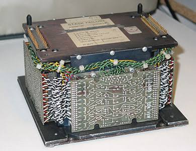
"Cordwood Modules" - MTBF - from Jerry Berg May 30, 2013
|
A quick comment on the MTBF.
Initially the cordwood modules used precision machined aluminum heat-sinks (face plate).
A cost reduction changed to a cast aluminum that had a draft angle where the 6 screws attached the PC board.
That angle put pressure on the surrounding solder joints when the screws were tightened.
... The fix was simple; reflow the solder on both sides AFTER tightening the screws. The problem was ensuring
that all field units got returned.
...
I recall writing about a 5 page memo describing the problem, root cause, corrective action in the late 60's (probably 67-68).
I worked in the Failure Analysis group, Quality Assurance under Geo Hamilton and Bob Olson at Arden Hills.
Jerry Berg
|
More "Cordwood Modules" - MTBF and other tricks ;-))
- from Dana Roth July 5, 2013
|
�Cordwood Modules" - MTBF
That explains why CDC 6600, (later serial), Department of Energy, Ottawa, was having a failure 2-3 days
after a power loss, from the thermal cycling of the cordwood modules. Up the block, the CDC 6000 early
serial (102?) at Computing Devices, Nepean, Ontario would only have one fault a year, no doubt because
they had the early machined modules. Thanks for clarifying this, now I�ll sleep at night :-)
For Customer Engineers, knowing the �tricks of the trade" kept things going, like:
- Removing the brake belts from the 844�s on day one.
- Aging punch cards for 6 months before use, to allow the ink
to dry so your card punch would not jam.
- Don�t touch the 808 storage for any maintenance until they died.
- Change the vacuum tubing to steel re-enforced tubing and use the pre-grooved tape heads
on 66x tapes.
- Get a tape certifier, clean three times and certify all new tapes, and send back 90% of new
�garbage� tapes back to IBM/Memorex!
- Test your 66X caption motors as 90% would be damaged in shipping!
- Change out those PCB riddled General Electric motor capacitors (the ones with the internal
�quality approved� ink stamp, that would break down under heat and explode)
- Putting foil on your channel cables for shielding.
- And above all, don�t lose your cookbook with the initial machine timing specs!
One piece of software I was always enamored with was the CE maintenance scheduler program.
It was a brilliant piece of work that saved lots of dollars in maintenance, which was a cash
cow for CDC. It promoted putting your effort into the top critical maintenance elements based
on a blend of past knowledge and performance.
Somehow, �Quality� never seemed to correlate real events in the field until you would do something
to get noticed like: Sending back and ordering one $5,000 motor a day till it was recognized the
glass tach wheel was always getting damaged! CDC, at the time, didn�t promote the culture that
allowed a matrix of organizations to solve issues (as this wasn�t an industry standard).
One
cultural difference CDC did have over many companies was that from Bill Norris down, everyone
was on a first name basis, which did promote many cross organizational ideas and solutions!
Dana Roth
|
|
Software Adventures - everyone has software troubles, so lets call 'em adventures
Seymour Cray even developed the first Operating system for the CDC 6600 !!
|
Seymour Cray made an operating system to demo his very unusual CDC 6600. I was rather
basic, we called it "Chipawa Operating System". I was very basic, maybe no time limit,
no reserving tapes for a job, ... but demoed that here indeed was the world's fastest
computer, with user memory protection so that multiple programs could be safely "running"
at the same time. While one user program was waiting for I/O, another user program
was given the main processor for execution.
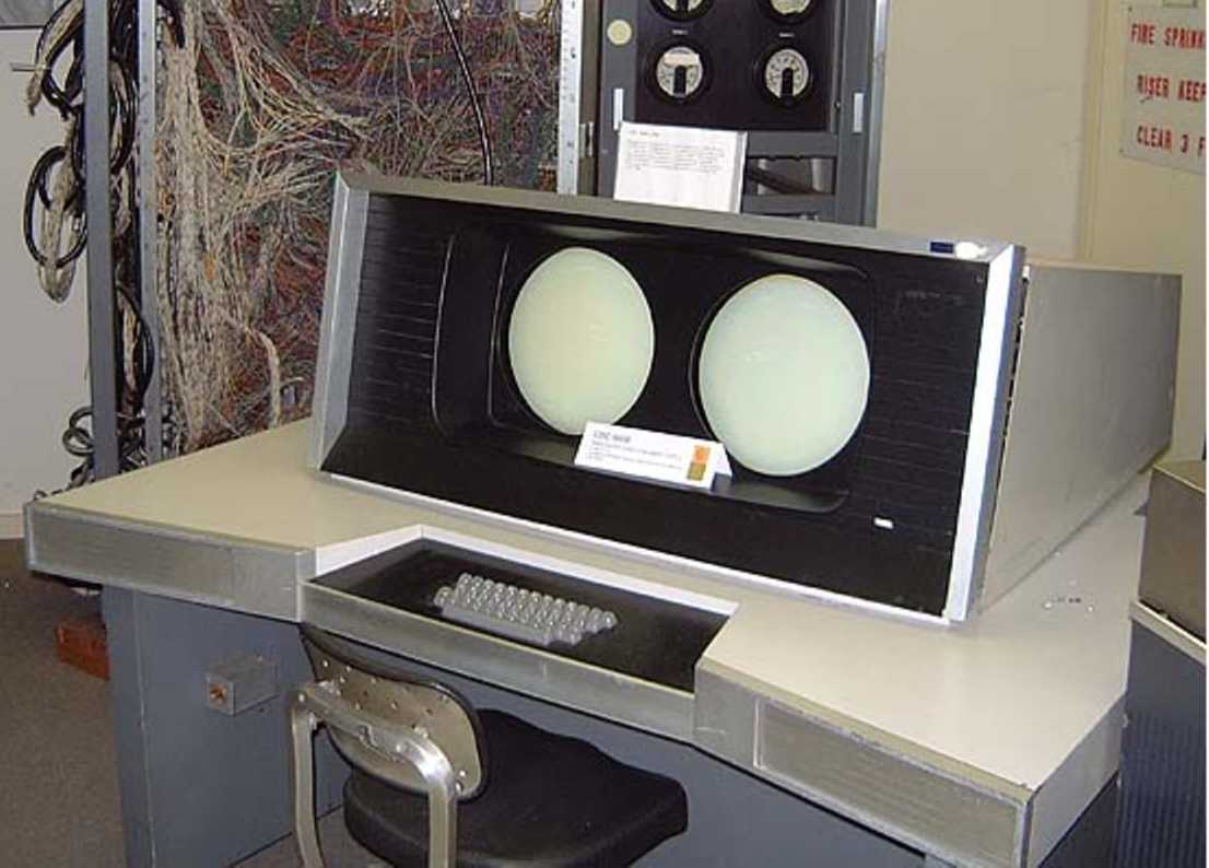
A summery presentation of the status of the various jobs was presented to the operator
as a selectable display on either of the two big round CRTs on the operator's console.
The basic plan was 8 horizontal zones
- 7 for the maximum number of user jobs in the system
- the 8th, bottom, for I/O status, printer 3 out of paper, tape drive 5 rewound, ...
Two operating systems came from this, and used the same basic display form
- Kronos/NOS by Dave Cahlander and Greg Mansfield, used in many colleges for students
- SCOPE, more formal, more useful features for general purpose.
A Tale
The CDC 6600 had great user protection, program A could not access program Bs memory or resources.
BUT we heard tales that the CDC 6600 in Palo Alto, California was getting crashed !!!
A job would come in from a particular authorized user, with a particular name - maybe "CRASHER",
and the whole CDC 6600 would soon be unable to do anything useful.
It turned out that Control Data's operating systems did not provide a maximum
per user allocation for the system disk,
the "CRASHER" user figured out this weakness, kept writting to disk until it was filled,
and prevented others from using this vital system resourse, such as spooling to printers ...
This exploited weakness was quickly fixed :-))
From Lew Bornmann March 2012
| We initially met at CDC just off E. Weddell Drive (near the Blue Cube) in Sunnyvale.
I was hired just prior to everyone moving from the Porter Drive facility in Palo Alto so essentially
was the first person working in Sunnyvale. I was one of three managers developing the replacement Scope OS for the 6000 series.
When we fell behind on the development schedule, I pert charted where we were and what we still had to do showing there wasn�t
any way we could deliver in time to meet contracts � and development was cancelled. What we had was moved back to Minneapolis and
relabeled as Scope for the 7000 series. Since I had just moved in from Madison, WI, I requested not to be sent back. They gave me
a research project which turned into Query Update and the database product line. I also worked on the distributed OS for the
Bank of Switzerland and the PL/1 compiler.
|
"Lifted" from linkedin.com
From Paul Derby, Enterprise Architecture and Innovation Advisor at Gartner
|
A Seymour story that was passed around many years ago recounted an interaction between a conference attendee
and Seymour talking about the design and performance of the 6600. The attendee repeatedly complained about
the performance of APL on the 6600 systems, APL being his programming language of choice. After several
comments back and forth Seymour shut down the complainer saying he wanted a computer that would run Fortran
so he designed and built one. If the complainer wanted a computer that runs APL well he should do the same.
|
e-mail from Eugene Miya - Sept 5, 2018
Eugene quotes an anonymous person as follows:
|
As one who rewrote the Optimizing Fortran compiler for the CDC
66/7600 series (1972-74) I should speak up about bad hardware design
and the problems I had to try and solve.
The CPU register set in the 66/7600 machines consisted of:
8 60 bit 'X' registers used for computation.
8 18 bit 'A' registers used to hold memory addresses when data was
loaded into or stored from the 'X' registers (A = Const, A+-B, ...)
and
8 18 bit 'B' registers used to generate addresses for indexing, ...
( B+B, B-B, B+constant).
One loaded/stored data into/from an 'X' register by setting a value
in the corresponding 'A' register.
This oddball set of 'green and purple' registers as one associate
called them caused me no end of problems.
To further make the problem more difficult,
of the 8 'X' registers,
one could only load operands from memory into
5 of them and store out of 2 of them.
In addition, double precision operations, which were quite frequent
in the scientific codes that the machines were 'designed for',
clogged up the 'X' registers.
In addition, because the machines had multiple functional units
capable of running concurrently, the compiler tried to minimize
computation time by overlapping the execution of the instructions.
Given all the above, I did not have fun writing the register assigner
for the machines. It was a total exercise in frustration.
Their were many nights when torture or murder of the hardware designers
(Jim Thornton was responsible for the CPU design) was more than an
idle thought.
BTW, the HW designers justified (rationalized) their divvying up of
the 'X' registers into 5 load and 2 store registers based on studies
of scientific codes in some idealized situation.
What they didn't realize is that they created a asymmetric monster
with irrational constraints upon the software people.
The real problem with the 66/7600 series was the 60 bit word length.
Re-designing the machine with 64 bits would have allowed one of add
one bit to each instruction so as to double the number of opcodes and
have a load/store bit in the memory reference instructions.
The other problem with it and many other early machines was it's
limited address space which eventually killed it.
{ Comment from Ed Thelen - Boeing Aircraft had a special modification which doubled address space,
but few machines had that modification.}
|
|
A view of the end of Control Data
- I ( Ed Thelen ) bailed out in 1972, thinking they were off track
- Control Data was trying to get into the commercial data processing business.
Someone sold a CDC 6600 to the United Bank of Switzerland - imagine a world class
60 bit floating point machine (could not do directly an integer multiply or divide)
trying to do banking transactions with any cost efficiency. Trying to compete
with the IBM 360 world which was among other things byte addressable
and could print both upper and lower case, and ...
I knew several Special Systems Division people working on that bank project - they were morose.
- Of more immediate interest, the sales force for Special Systems was called back to Minneapolis -
Hard enough to educate/work_with sales (Special Systems was in Sunnyvale, CA) when local.
Message: 8
Date: Tue, 06 Dec 2011 15:42:58 -0800
From: "Chuck Guzis" < cclist@sydex.com >
To: "General Discussion: On-Topic and Off-Topic Posts"
< cctalk@classiccmp.org >
Subject: Re: The Strange Birth and Long Life of Unix
Message-ID: < 4EDE3802.24413.8376F7@cclist.sydex.com >
Content-Type: text/plain; charset=US-ASCII

On 6 Dec 2011 at 9:52, Al Kossow wrote:

> I was just digging through some CDC documents we just received
> concerning the joint CDC/NCR developments that happened in the early
> 70's, and was thinking how fast the pace of system change is now. The
> system they started on in 1973 was ultimately released almost 10 years
> later as the CYBER 180. By the end of the 80's they were thinking of
> porting Unix to it. I can't imagine anyone taking 10 years today to
> develop a new computer system, or thinking of writing an operating
> system and tool chain from scratch.

To be fair, you have to understand the times and the culture. In
1973, the dominant storage technology was still core. Backplanes
were still done with twisted pair and taper pins. The Cyber 70 line
was mostly a cosmetic rework of the old 60s 6000/7000 series.

The 170 series migrated to ECL ICs instead of discrete transistors
and semiconductor memory. Compared to everything that had gone
before, it was major, even if the same old architecture (6 bit
characters, ones' completement) and instruction set was being
implemented.

The dual-personality Cyber 180 was a major rework of the basic
architecture, even if most CDC customers operated the systems in 60
bit mode to be compatible with the old hardware. While the
6000/7000/Cyber 70/170 systems had a very clean simple RISC design,
the 180 was anything but--sort of the response to the sucker question
"What instructions would you want for product xxx?". For the system
programmers, little nits such as the move to twos complement,
hexadecimal notation and reversing the order of the bit numbering in
a word were just icing.

The times were another factor. Seymour Cray's going off and doing
his thing hurt CDC's high-end sales badly. CDC's fortunes rapidly
declined and the 70s and 80s were marked by layoffs--one co-worker
committed suicide when he realized that having spent his career with
CDC, job prospects were limited at his age.

The NIH mentality of units within CDC hurt a lot. When one of the
Cyber 180 software architects gave a presentation of the 180's
operating system software sometime around 1976, I was furious when
the subject came to paging software. He described in some detail
what he thought the paging should be--simple demand paging. I raised
my hand and asked him if he'd discussed the matter any with members
of CDC's other 64-bit virtual-memory machines already in production.

He looked at me as if I'd just informed him that he had an unknown
twin brother. I told him that STAR had been working with the
technology since 1969 and that demand-paging was going to give him
grief. I suggested that he talk to our pager guy about working-set
paging. I don't think he ever did.

And finally, a lot of the talent had flown the coop. Seymour was
gone and had taken a bunch of key talent with him. Jim Thornton was
consulting and playing with a loop of coax that ran around the
parking lots at Arden Hills. And a lot of other talent had left to
join the early microcomputer scene in California.

It was surprising that CDC lasted as long as it did.

BTW, in 1984, I strongly suggested to Neil Lincoln that ETA adopt
Unix as the OS for the ETA-10. To his credit, he agreed with me, but
failed to convince others. Eventually, ETA did have a Unix port done
by an outside firm, but by then, it was too late for them.

--Chuck
|
|