Trip Reports to, and info about,
Allen Telescope Array (ATA)
or Hat Creek Radio Observatory
42231 Bidwell Rd., Hat Creek, California
Google Maps
W 121, 28' 13" - N 40, 49' 36" (gate on Bidwell) - 1009 meters altitude
W 121.47028 - N 40.82667
I visited Wednesday June 7, and Wednesday October 31, 2007
The cable entry to the electronic processing room is -121.46915 W, 40.81722 N
by Ed Thelen ed@ed-thelen.org
Goals
- Present information gained from two trips to the Hat Creek Radio Observatory (HCRO)
containing the Allen Telescope Array (ATA)
- Provide other information gleaned from many sources about ATA
- Provide other information and links - Wikipedia
- Techie info only - the worlds of planning, begging/scheming, permitting, acquiring, maintaining, staffing, ... are ignored -
Organization of this document
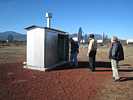
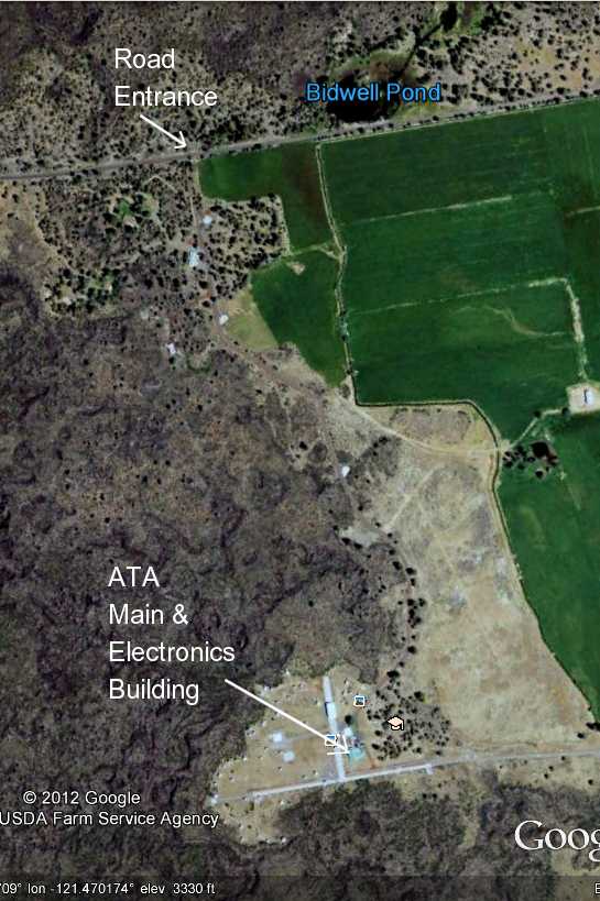
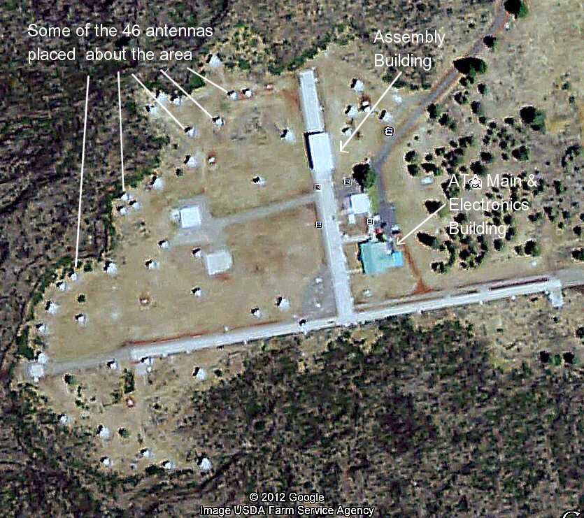
Arrival at ATA
I (Ed Thelen) have been to ATA twice, with friends. The main contact at the site is
Susie Jorgansen (tel: 530 335-2364) (site manager).
( Images to right are from Google Earth )
|
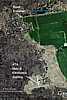
Overview
|
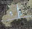
Detail
|

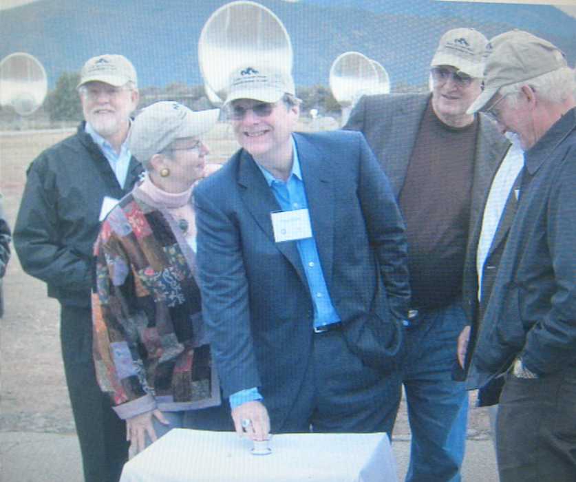
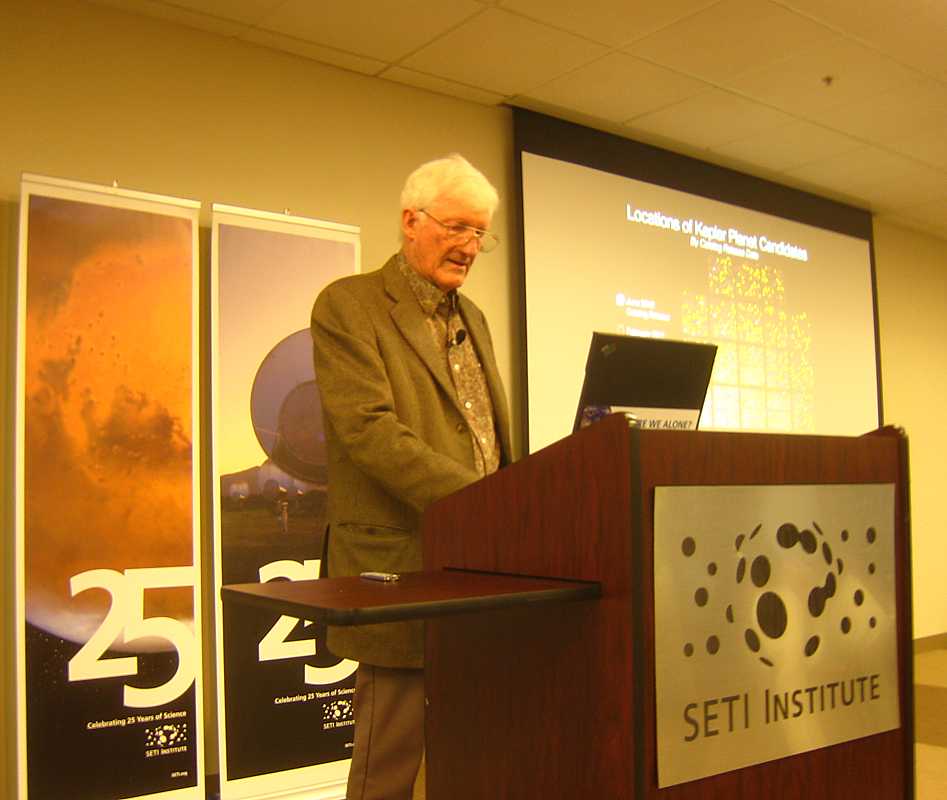
Paul Allen
| The second trip was delayed one week to avoid the excitement of the formal dedication of the
Allen Telescope Array.
OK, I wasn't invited :-| This day was for the wheels and heavy hitters -
Image from April 9, 2008 presentation by Tom Pierson, CEO of SETI,
available at
http://www.seti.org/csc/lectures.php
|
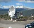
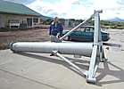
ATA is about 13 miles south east of Burney, California. From Hat Creek the route is well marked. Driving along Bidwell Road we notice an antique looking 6 foot dish
atop a weathered looking 30 foot wooden tower. This place seems to have quite a history. A quarter mile further on we arrive
at a lockable gate stating the visiting hours.
An associate sets up chairs to form a little theater in the entrance hall
and visitors are shown two introductory movies from a DVD about the history of the Hat Creek
facility and the current ATA - Much of the following section is from History of HCRO.
|
History of Hat Creek in Radio Astronomy
| In 1962, an 85 foot radio telescope was constructed here, and several very significant discoveries took place here
- including first interstellar maser, detection of molecules of water and ammonia in "outer space".
In the 1970?s Berkeley astronomers developed a two dish centimeter wavelength radio interferometer at HCRO. This evolved into an array of
10 dishes operating at wavelengths of 1 to 3 millimeters. The 10-element array was called BIMA, named after the consortium of
universities that operated and helped fund the instrument (Berkeley, Illinois, and Maryland Association).
Around 1993, a wind of over 100 MPH lifted the 85 ft. antenna out of its supports and dumped it crumpled on the ground.
|
Much of the BIMA array was moved to CARMA in Cedar Flat at 7,200 feet in the White Mountains near Big Pine, CA in 2003 to minimize water vapor
absorbing the high frequencies. View in Google Earth
All except this old warrior - abandoned as just too old and worn.
| 
|
SETI
and Berkeley Radio Astronomy Lab proposed a big (350 antennas) array of 20 foot (6.1 meter) radio telescopes
connected in an array - with up to 16 simultaneous studies going on at once - basically 16 somewhat independent
data streams coming
from the electronics - limited to a circle in the sky of about 5 degrees diameter at any one time - the (frequency dependent)
beam width of a single antenna. The above is a simplification of many options, including
splitting the array into parts for more data streams.
Paul Allen (of Microsoft fame) seems to have paid $12.5 million to initially get things going,
and committing another $12.5 million depending upon progress.
Nathan Myhrvold (also of Microsoft fame) apparently donated $1 million for the central electronics to do the magic of forming
and utilizing the somewhat independent 16 data streams (or 8 if using both horizontal and vertical polarities).
U.S. Navy has donated $1.5 million in return for usage time.
There are also a number of other donors of significant cash and useful products. Susie mentioned that Xilinx has donated
several million in the form of FPLAs (Field Programmable Logic Arrays) and technical help. (Both LaFarr and I had purchased
Xilinx chips and development systems. :-))
| Each antenna costs about $150,000 installed.
There are a number of donors of $150,000, each of whom get to have his/her name placed on an antenna.
| 
|
Reading:
History of HCRO
wikepedia
an AAS meeting summary
|
Commercial Credits
Other than some help in return for telescope time by the ONR (Office of Naval Research), this ATA is largely privately
funded. (University of California Berkeley also helps) Here are the commercials posted by the Computation Center:
| Vendor
| Donation
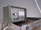
| Agilent
| A signal generator and spectrum analyzer used for testing and monitoring ATA protoype test array signals
| | x
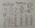
| Sun workstations, LCD monitors, disk arrays and tape units used in SETI's Prelude system, and the massive
storage system for ATA imaging data
| | Trimble Navigation
| The differential GPS positioning system used to establish the ATA antenna locations for the 350-element array
| | Xilinx
| FPGA (Field Programmable Gate Array) chips for the ATAA's BeamFormer, Imaging Correlator and SETI PDMs
Programmable Detection Modules)
| |
|
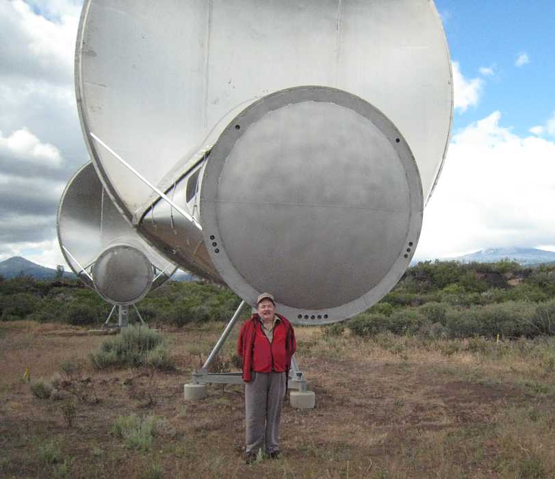
Our guides :-))
Since our announced purpose of visiting was to view techie stuff, Susie Jorganson always had a technical person
available to answer our questions :-))
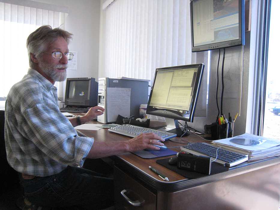
| Rick Forster (Resident Astronomer, with overview of technology) at his desk overlooking the array.
The top screen shows the web cam image which he can point and zoom
for a view of outside and antennas. Local temperature and wind is also available.
| 
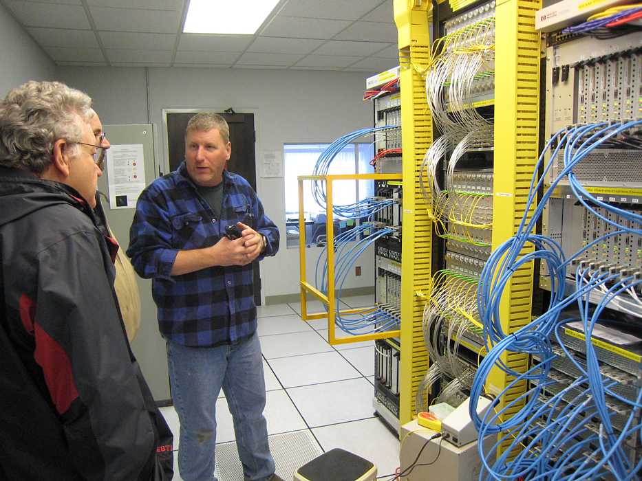
| Jeff Chero, [jeffchero at berkeley dot edu] - electronics, our October guide, in the processing room. His other lair
is the electronics work room.
| 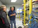
| (not shown, Jeff Kaufman, Power Electronics Technician, our June guide.) I also talked with
Geoff Bower [GBower at astro dot berkeley dot edu] in Campbell Hall in Berkeley.
|
|
Visitor Problem - Information Overload
| The major problem for a techie visiting ATA is information overload. There are so many specialty fields
necessary to make phased array radio telescopes point, receive and process data that the mind boggles at such a listing.
Every subsystem seems a career specialty - antenna design, antenna pointing, low noise amplifiers, laser transmitters and receivers,
fiber optics, highly stable frequency adjustable local oscillators, rf mixers,
radio interference measurements/remedies, ADCs, digital radio techniques with digital down converters and filters,
FPGAs, ... image synthesis, computer programming,
and on and on ... most of which have had continual major upgrades in the past 20 years. And being a
LINUX guru is almost necessary.
When I was a kid, astronomy was kind of a back water - learn a little optics, a book or two of astronomy, some statistics, a thesis (that you could explain to "the man on the street")
and you were employable? Now everything seems to be on the bleeding edge of progress in so many new fields. :-(( ;-))
I have no clue how a current astronomer has time for astronomy. :-((
|
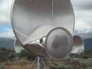
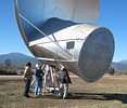
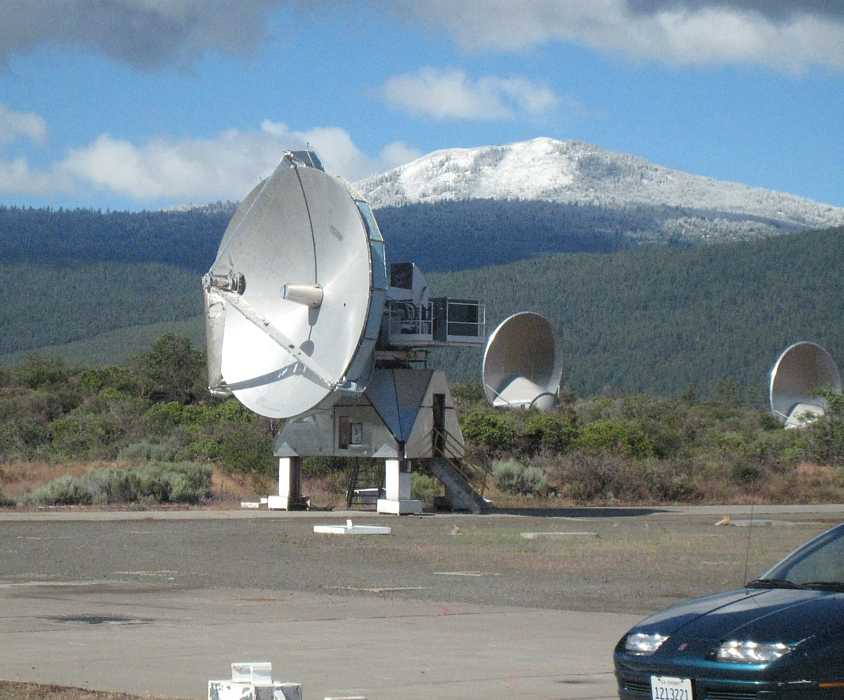
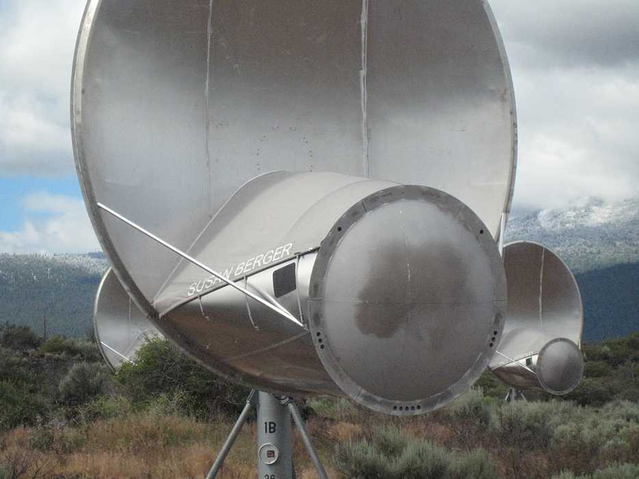
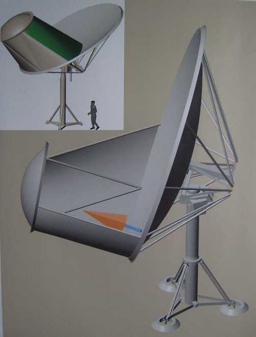
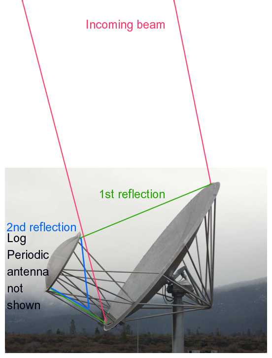
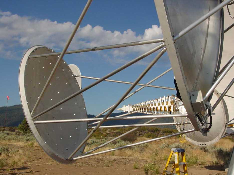
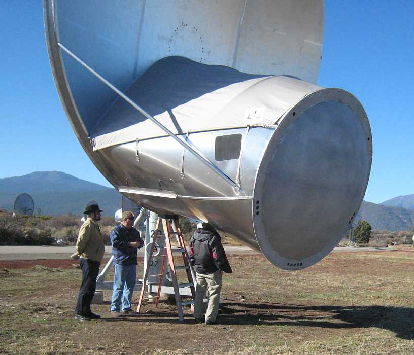
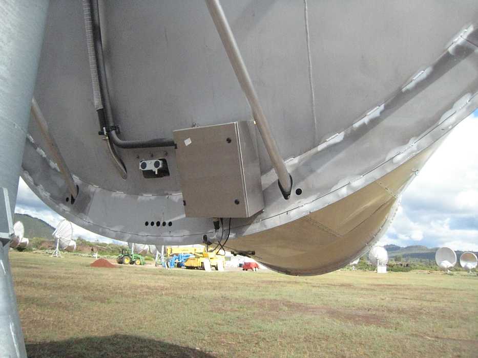
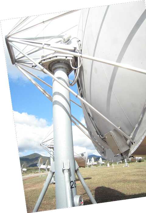
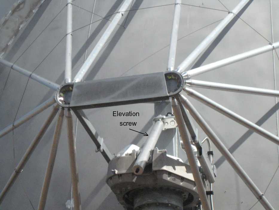
Offset Gregorian Telescope, "Antenna"
Pointing the Telescopes, Brakes
Log-Periodic Wideband Antenna, Inside the Gregorian Telescope
- also see - 2012, upgrade to "Antonio Feeds", below
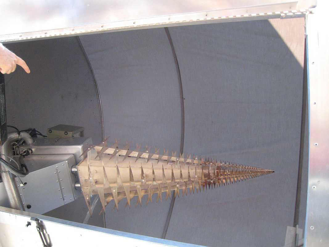
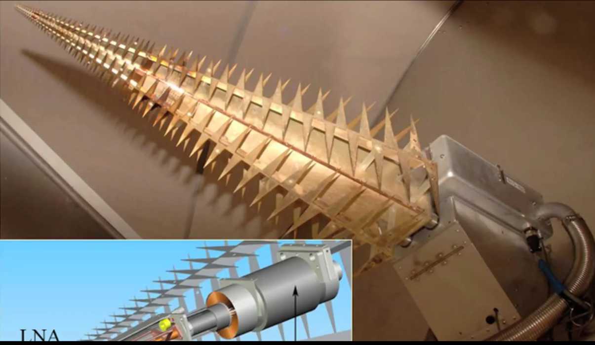
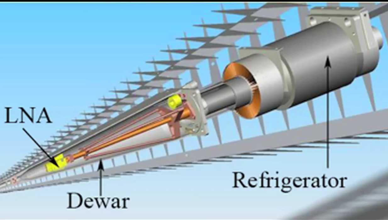
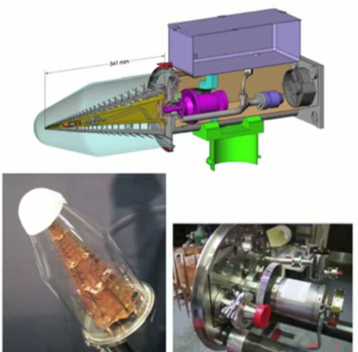
| This is inside the protective cover in the antenna. The
Log-Periodic antenna
inside in about 2.5 feet long.
It can efficiently receive a VERY wide range of
frequencies - from about 400 megahertz (wavelength about 30 inches) to 11,000 megahertz (wave length less than
3 centimeters, about an inch) The little fins at the pointy end are about 1/4 inch long.
This converts the radio waves reflected by the dishes into electrical signals. The base of the Log-Periodic is
on the left, and the tip is connected to the Low Noise Amplifier inside the copper structure. Notice that fins are in planes
90 degrees apart - this permits receiving both vertical and horizontal polarized waves. After amplification,
both vertical and horizontal RF is converted to laser light and transmitted to the Control Building.
more pictures
| 
|
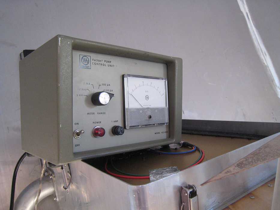
| This box is sitting on the base of the Log-Periodic antenna. Inside the Log-Periodic is a little cryogenic unit to make
*VERY* low temperatures, to cool the Low Noise Amplifier.
Apparently this (or every??) antenna has a vacuum monitor for the pump/refrigerator cooling the Low Noise Amplifier.
Inside of the base is a little motor to extend or retract the Log-Periodic a range of about 10 inches for
optimal focusing - see next lower box.
| 
|
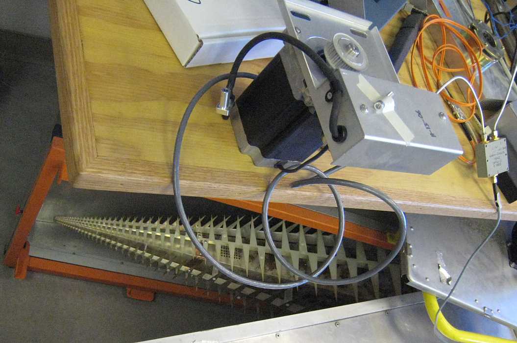
| The optimal position of Log-Periodic antenna is somewhat frequency dependent a focusing environment, such as a Radio Telescope.
The elements of this extreme log periodic are spread over a length of over 2 feet.
So, depending on general frequency you wish to receive, a stepper motor (Focus Drive) can slide the correct part of the antenna
into the focal point. Fortunately
the position is not very critical. Rick Forster says that improvement in setting gives a maximum improvement of about 20% :-))
| 
|
| This image of the cooled (to about 40 Kelvin) low noise amplifier comes from an on-line SETI lecture
given by Jill Tartar Feb 16, 2008, available at
http://www.seti.org/csc/lectures.php.
With I presume tongue-in-cheek, she said it amplifies "... basically from DC to daylight" ;-))
She then said that with the log periodic antenna (above) (feed?) they receive 500 megahertz to 11 gigahertz -
a range of 22 to 1.
|
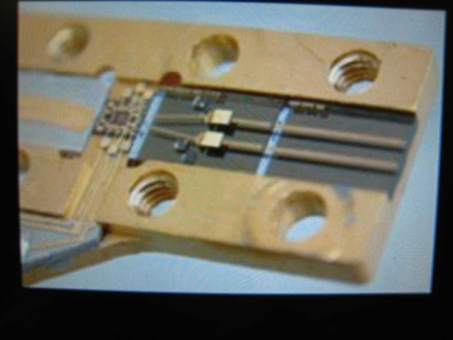
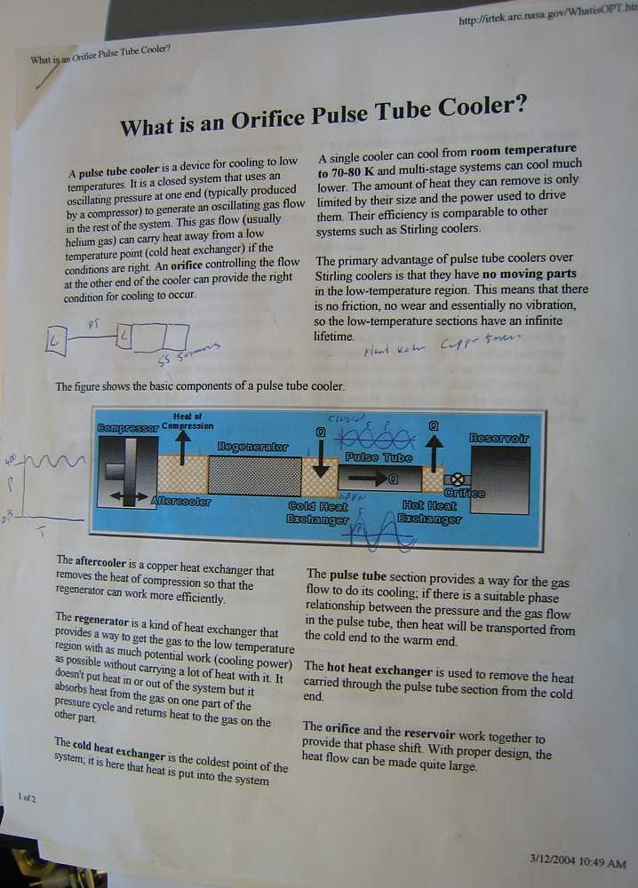
| A refrigerator is used to permit the Low Noise Amplifier (I did not get a picture)
to have even lower noise, the Low Noise Amplifier is cooled to well below the boiling point of liquid nitrogen.
The refrigerator (called a Pulse Tube Cooler) is contained inside the pyramid of the log periodic antenna above.
The general idea is similar a household refrigerator, compressing and expanding a gas,
with but with changes for smaller size and longer life. This is a reference to a
Pulse Tube Cooler, which unlike a Sterling cooler,
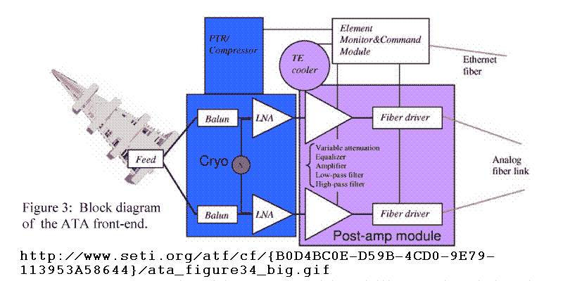
has no moving parts on the cold end. also.
A SETI Block Diagram.
| 
|
|
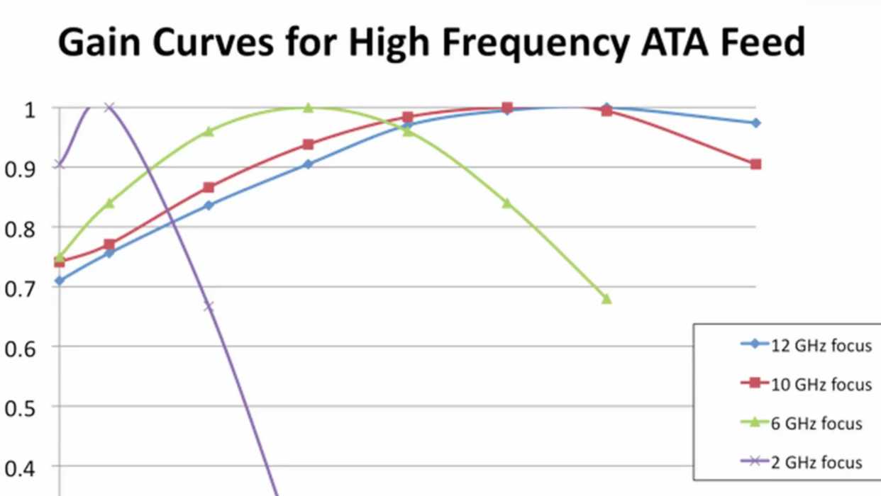
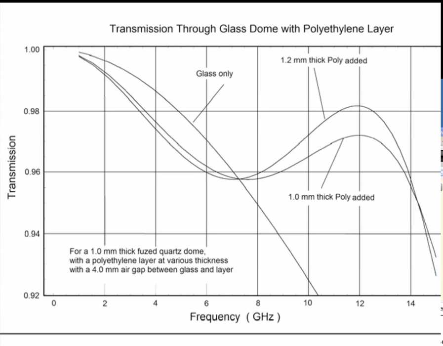
- 2012, upgrade to "Antonio Feeds"
HOT FLASH April 2012 - Jack Welch and associates have developed a second generation
log-periodic antenna with lower noise and wider bandwidth.
See this SETI March 21, 2012 presentation !!
Announcement from Jill Tarter - November 14, 2012
... I am so pleased to tell you that through the generous gift of Franklin Antonio, co-founder and cheif scientist at Qualcomm, the Allen Telescope Array will be receiving an important upgrade.
Excerpts from Jack Welch's presentation (above)
|
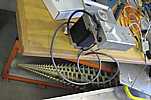
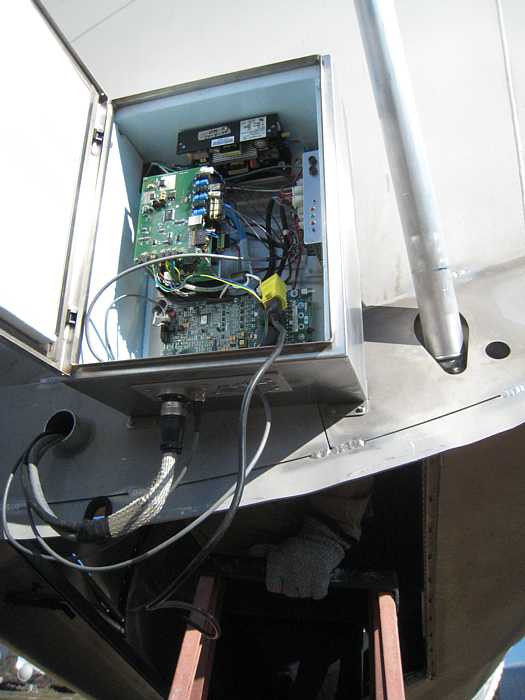
Fiber optic link to a Node
| After the cooled Low Noise Amplifier, the signal is strong enough to send to this
Amplifier box via coaxial cable. Here it is further amplified and routed via coax to the board with the laser. The laser
is connected to the blue fiber optic shown for transmittal to a node box which handles 12 antennas (24 channels)
Note that there are 2 data channels in this box, one for the vertical polarity radio waves, and the other for the
horizontal. The big green board in the middle is the amplifier control (suitably shielded.
| 
|
|
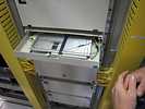
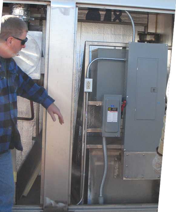
Node, then to central building
| The control signals and data signals from each antenna pass through a "Node", which is an organizing convenience,
no known technical use? The current organization is 12 antennas are 'serviced' by one Node. There is more
physical capacity in each node if the need arises. The chimney is for a ventilating system.
| 
| 
|
| Jeff points out the optical fiber entry and exit.
| 
| 
| and lots of spare power and space.
| 
|
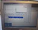
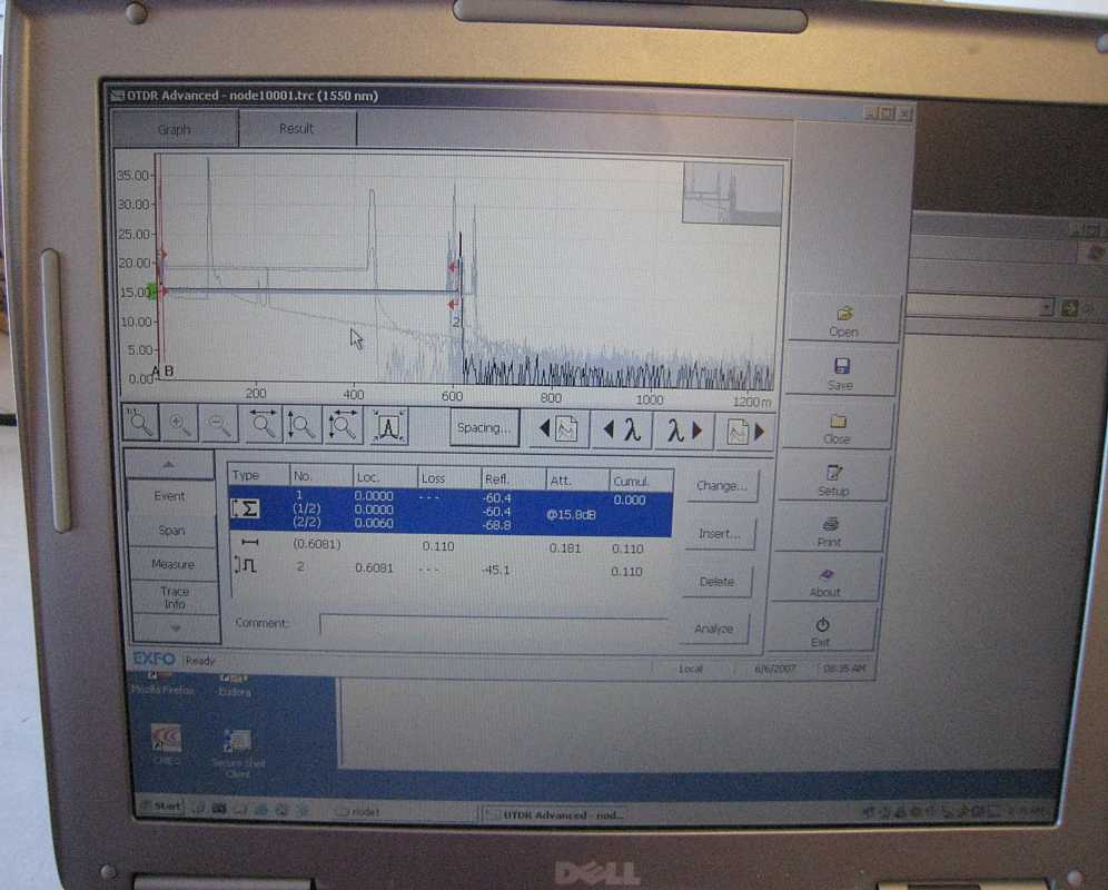
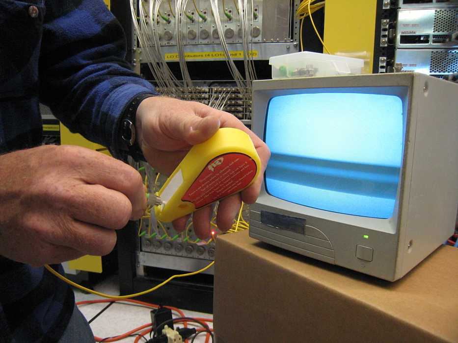
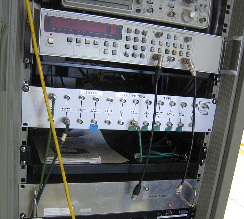
| Optical signals in the Central Building
This might be called an Optical Time Domain Reflectometer :-)) How about that for a mouthful ;-))
(as opposed to frequency domain).
It is useful in determining many characteristics of a fiber optic cable - such as how good are any splices or junctions,
where are they - as measured in time converted to length, various other imperfections, and very vital in this application,
how long in time to the other end as accurately as possible. With the game being to phase match every thing,
this is vital knowledge for initial setup of delay parameters to point the
electronically steerable sub-beams with in the physically steerable main beam.
| 
|
|
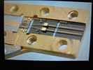
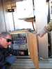
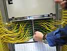
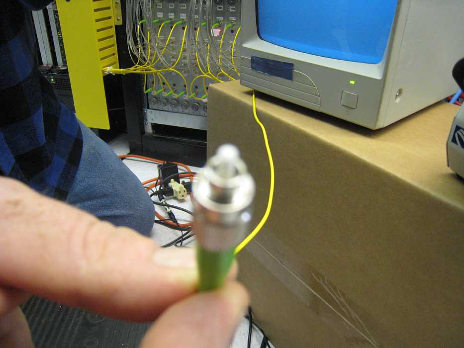
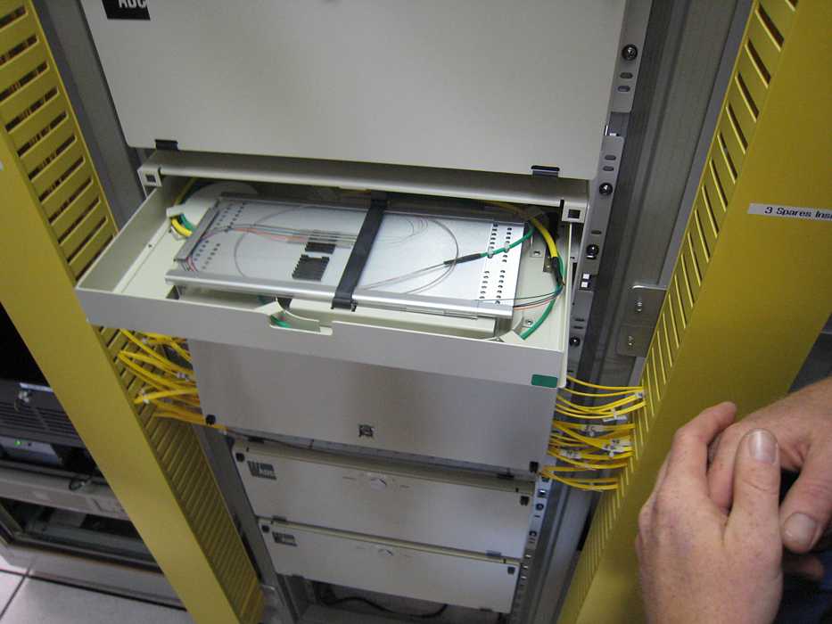
Splicing optical fibers
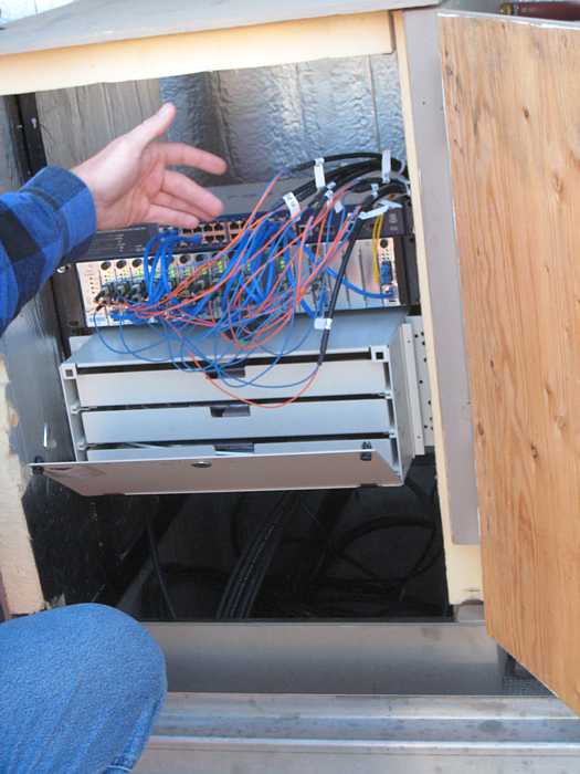
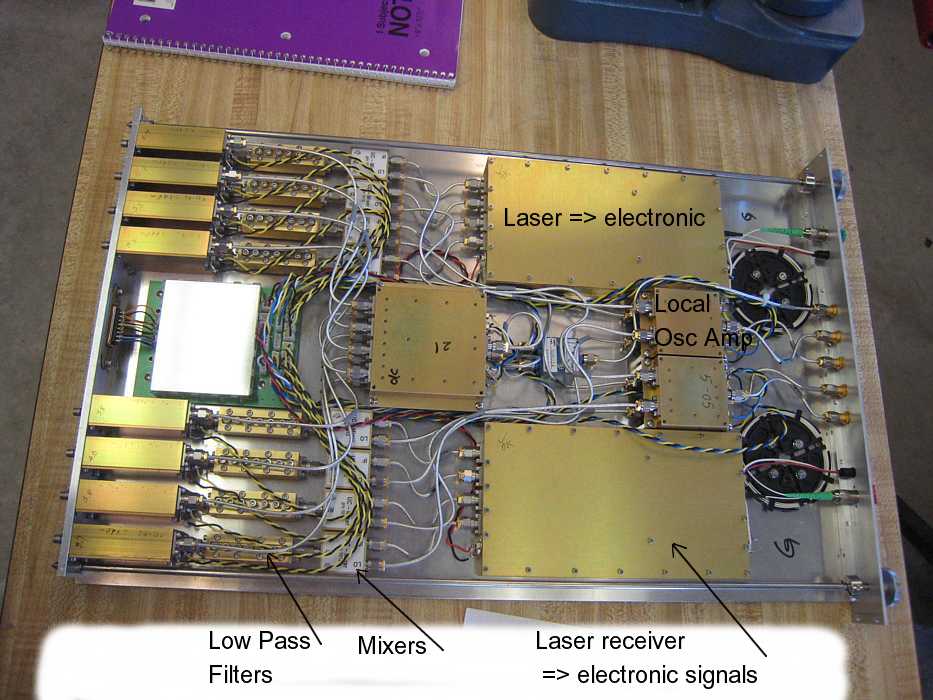
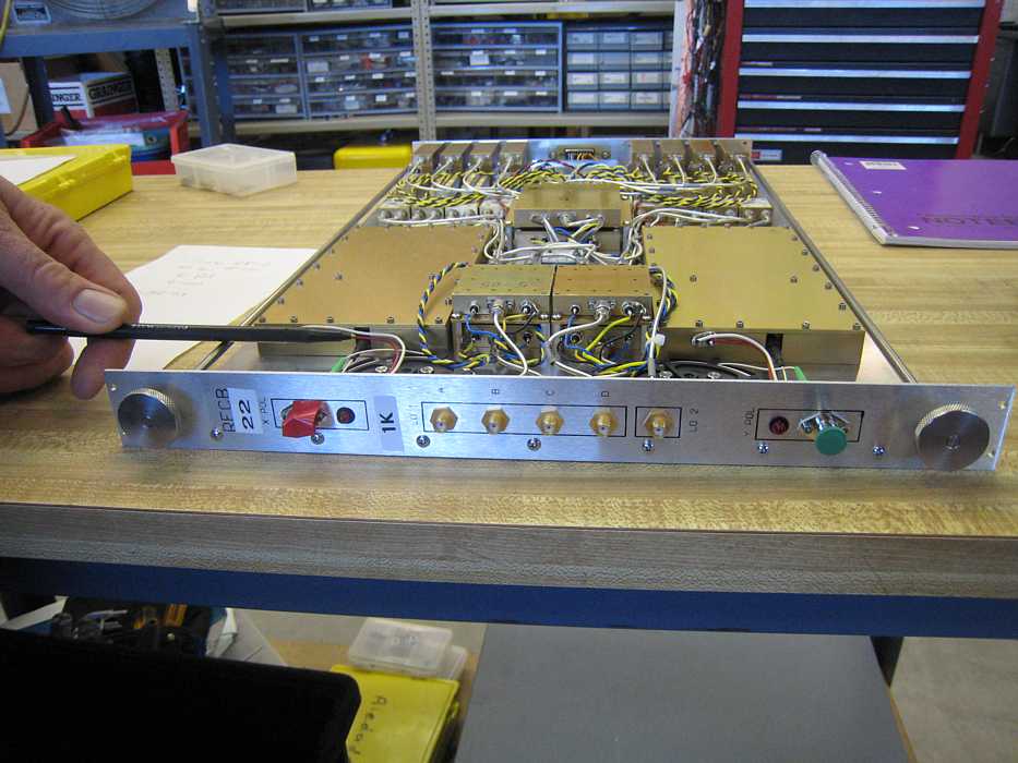
Central Electronics - now things get "interrrresting" :-|
Here we are in techie & mathematical heaven -
There are things going on in here I probably never understand :-(( And this version may have serious flaws :-(( - getting corrected :-))
However, lets get started - This is where the field fiber optics, carrying the vertically and horizontally polarized RF information,
come into the building and are joined to the patching system.
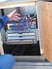
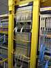
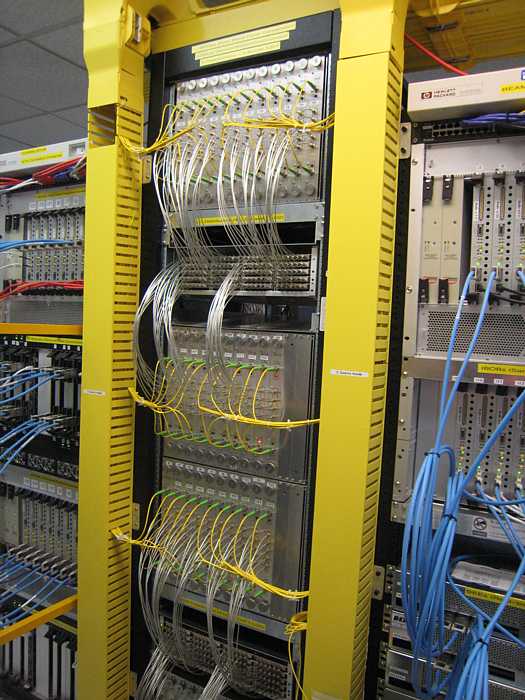
| And onto distribution (I think)
| 
| |
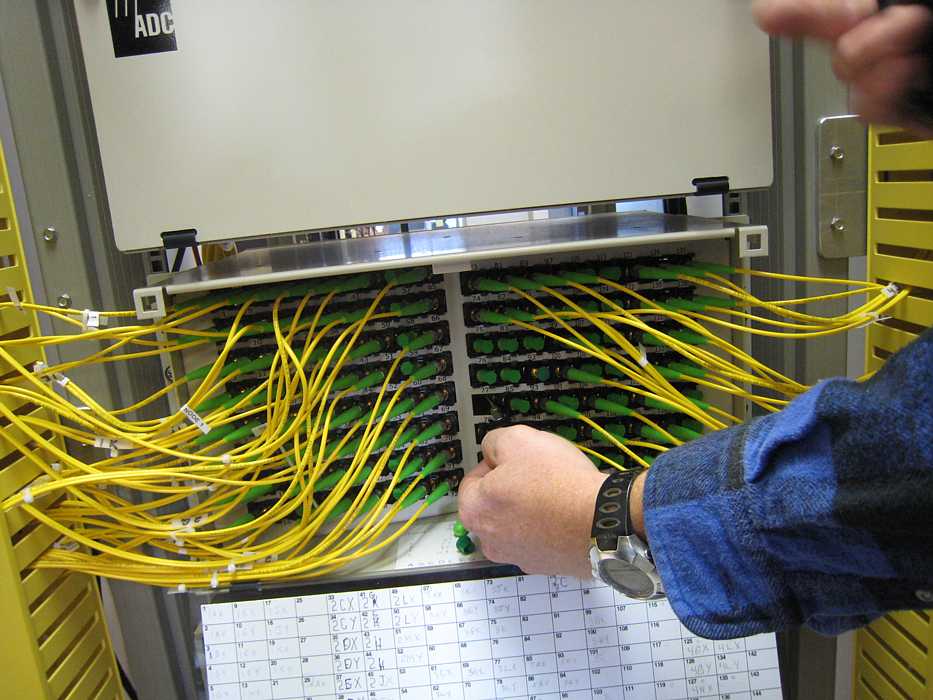
| And somehow the data (both polarities) gets into these
Radio Frequency Converter Boards1 "RFCB"- sometimes called "mixers" -
- with inputs from 4 separate local oscillators to begin generating the 16 separate data streams available for users.
| 
|
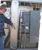
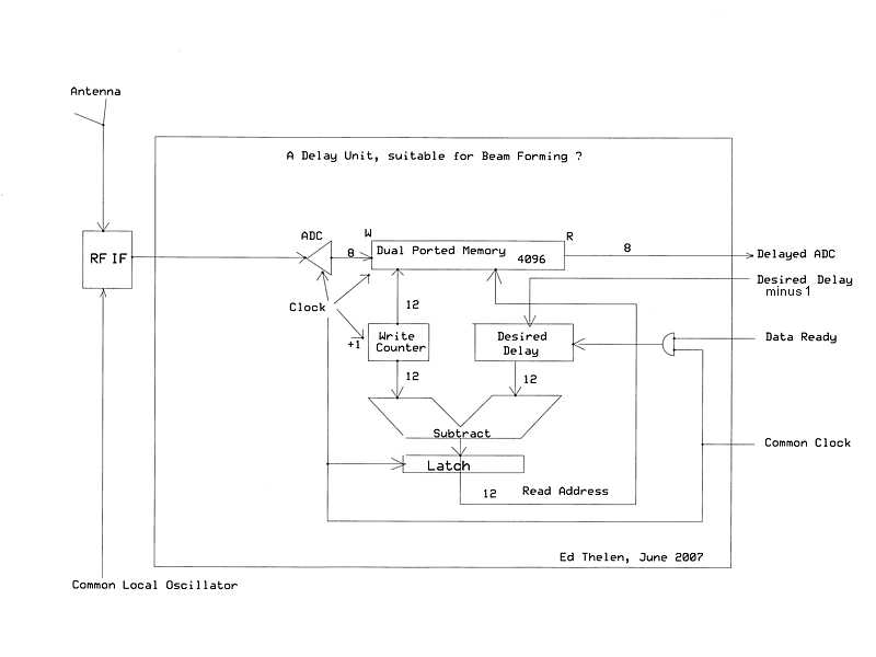
| The unfortunate part of all of this is that I came up to find out about the delay lines and correlators, as instructed by
the Berkeley folks, but that expertise seems to be elsewhere :-((
|
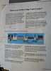
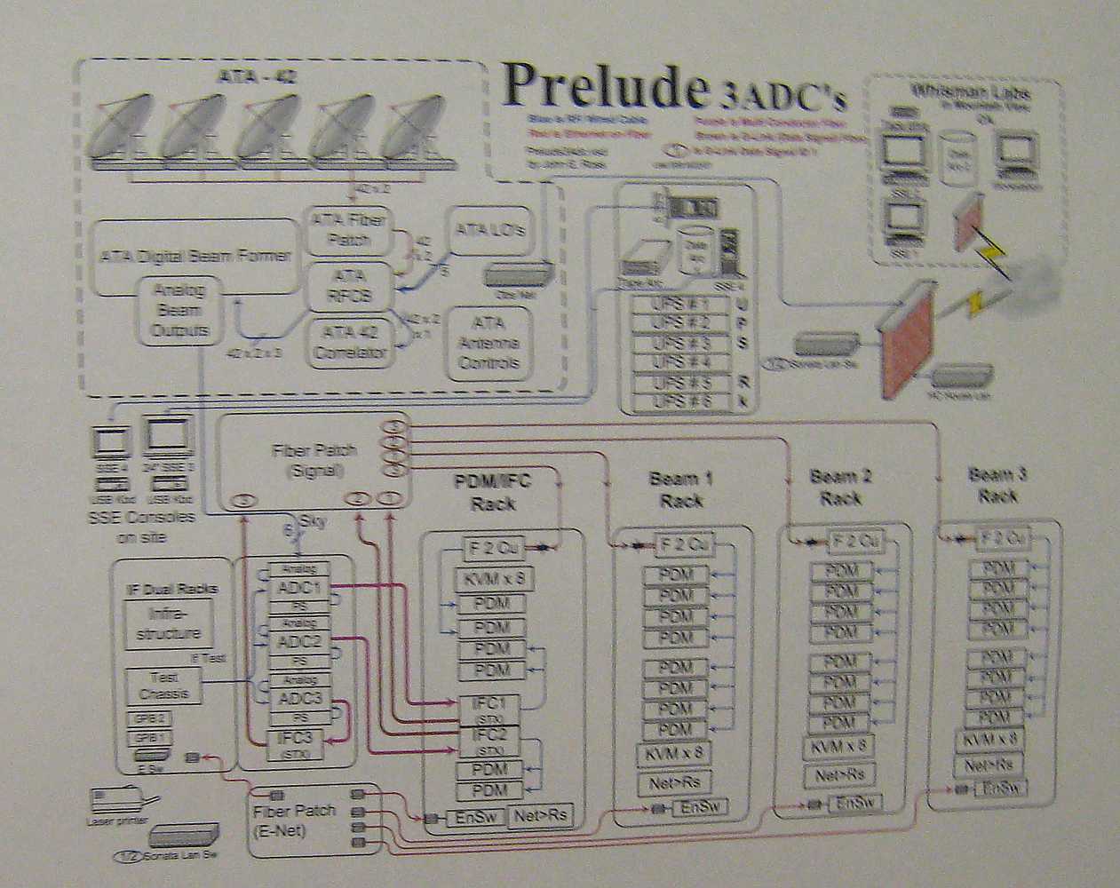
(Hot Update, Better, clearer, more up-to-date diagrams here.)
I found this diagram, specifying a 42 antenna system so I figure it is relatively current - I doubt that a year ago
they knew that this phase would be 42 antennas. The image here is large (124 K bytes) but still
hard to read but maybe worth the struggle if you have a tutor handy. I was particularly confused as it indicates that
the output of the digital beam former is analog, and goes to more ADCs. But then again, I'm guessing at the whole
thing anyway -
| 
|
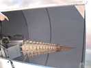
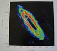
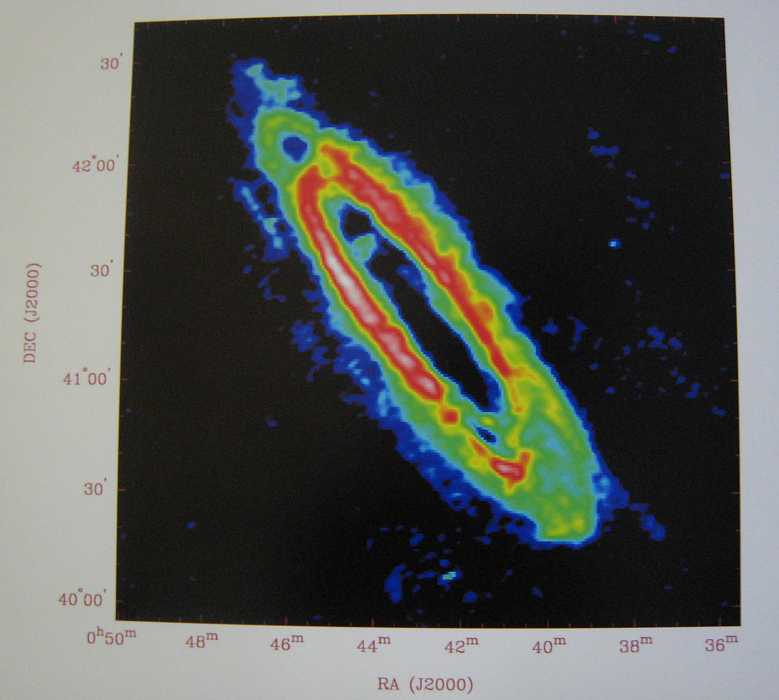
| But then I found this representation of probably brightness at some radio frequency of M-33 on the wall.
If you get tired of O-H radicals, Doppler shift, atmospheric absorption, calibration problems,
people problems, interference problems, scheduling problems, funding problems,
environmental problems, and all the other hazards of life, you can gaze at this
and feel good :-))
| 
|
|
Visit with Rick Forster
Susie Jorgansen then introduced us to Rick Forster (Resident Astronomer).
We talked astronomical things, including that these telescopes were "fast".
A "fast" telescope implies a short focal length and a large field. Fast, however, is a term borrowed from photography (an f/5 telescope can take a photograph with one-fourth the exposure time of an f/10 instrument).
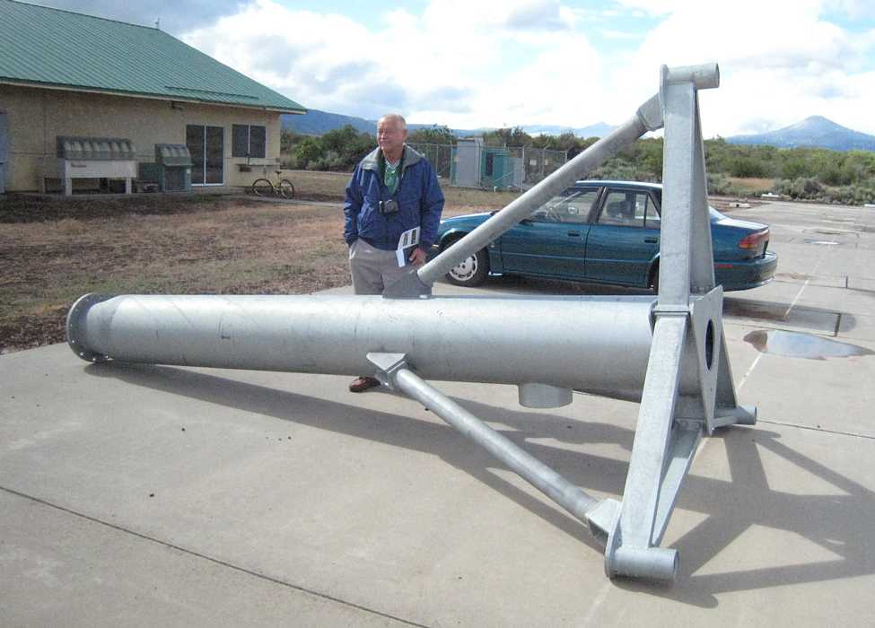
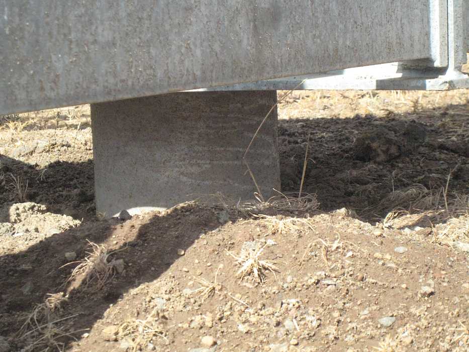
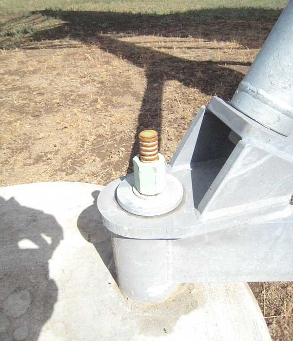
Rick started then talked about the nearby antenna pedestal. Apparently nothing in life is perfect,
and sometimes the "little things" can turn into "big things".

| |
|
For instance, when the sun shines on one side of the steel tube center post,
it can tilt the top up to 1/2 degree (the angle of a full moon). Rick called this effect "sunflowering", as in flowers following the sun.
This may not sound like much, but it is 1/5 of the average beam width
of the reflector telescope (much greater error if working at higher frequencies. There are other aspects of this that contribute more
errors, such as shifting the focal point of the antenna on the order of a wave length. As this whole array tries to have errors less than
1/8 wave length, this one problem makes a big contribution to the entire error budget of the array.
| 
|
| Rick said that this center post tilt error is difficult to model, and therefore difficult to correct in software or by other means.
I imagine that "random" breezes, patchy clouds moving about, and similar effects are most difficult to measure and work into a model.
I suggested that painting the gray (galvanized steel) center posts and supports with
titanium dioxide paint (very white and reflective)
might help - The Nike precision tracking antennas I worked with so many years ago used titanium dioxide paint to help fight this same problem.
Maybe the reason this is not done is that the glare white, desired for engineering reasons, is very noticeable in the surrounding woods
(a National Forest?) and offensive to the natural beauty of the area??
| 
|
| Of course we had to ask Rick how so many antennas could be used (in phase) together - it sounds like a mind numbing problem.
Rick said that you basically pair each antenna with every other antenna in the group, and that you want as many different distances
as practical. That this was why the field of antennas looks so random.
The goal, in part, is to place antennas so there is as large as practical range of differences in distances. There is of course some minimum
practical difference between two antennas, and a maximum practical distance between two antennas - but you really do *NOT* want the antennas
to be placed like rows of corn or a checker board or any regular order. For a very helpful article on the placement of the antennas and
why it isn't as random as it appears, read Dr. Seth Shostak's
"Spreading Antennas Around". They even use
heavy duty computing to help do a proper job.
|
|
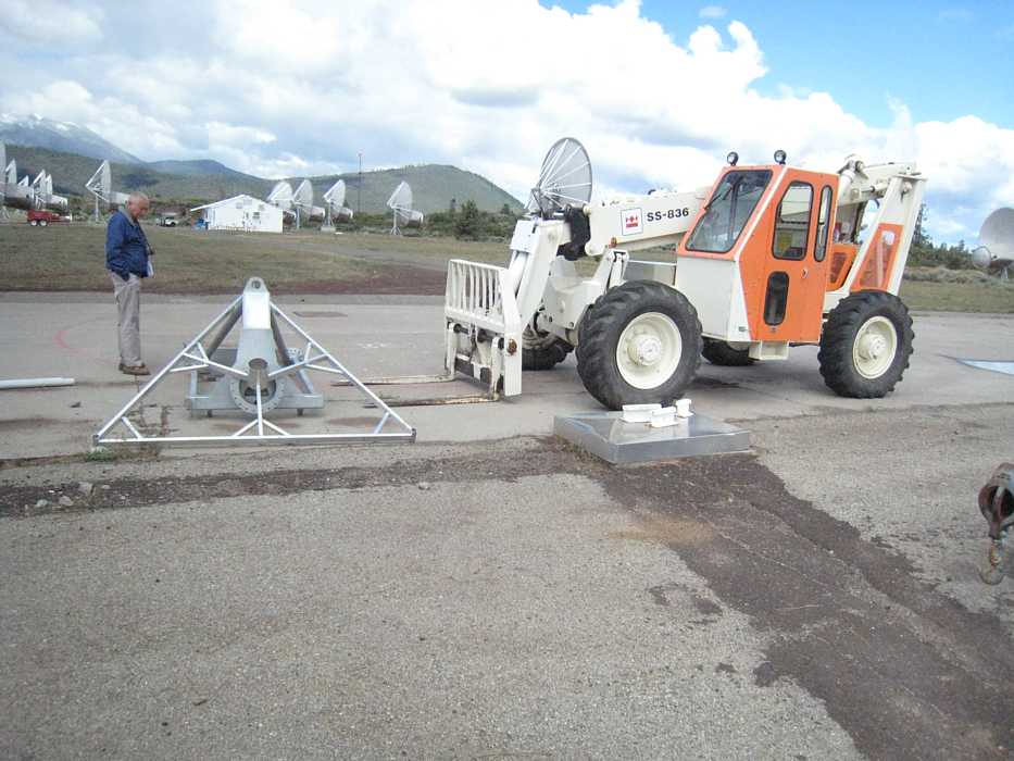
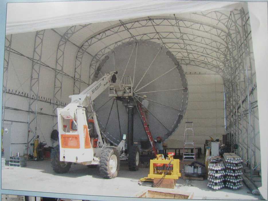
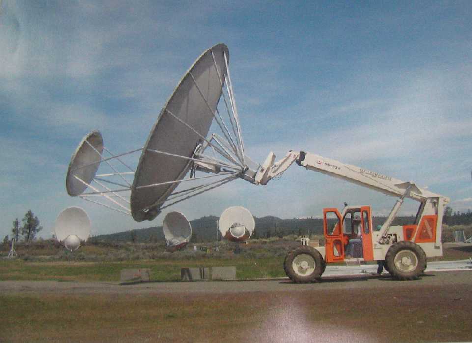
Roaming the Telescope Area
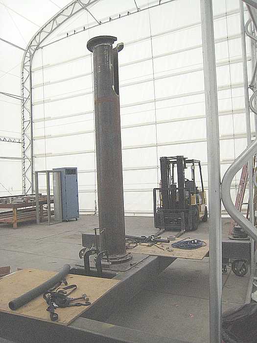
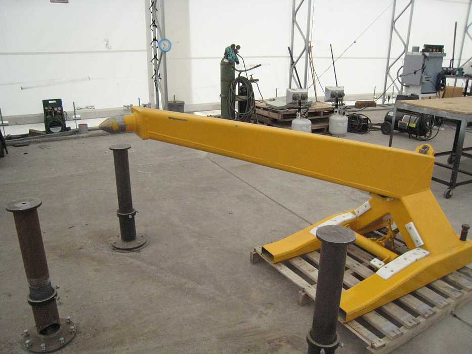
Assembly Building and Jigs
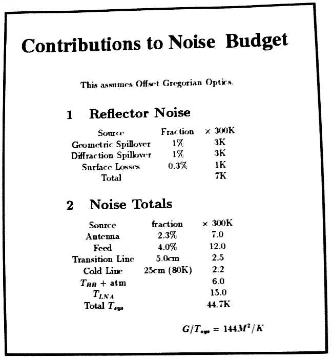
Noise
|
A reason for selecting this location for a radio telescope is the relatively low radio noise leaking in from civilization.
The surounding hills and mountains largely block noise from the earth outside. The rural location, and being in a National Park
provides low ambient noise. As you come into the ATA area, you are asked to turn off your cell phones - they all operate in
the frequency band (500 mHz to 11 gHz) observed by ATA. Unfortunately, EVERYTHING radiates radio waves, including you and me.
|
Carl Sagen is quoted as saying that all the energy ever received by all the radio telescopes in the world is less than that
of a snowflake gentle falling onto your hand. Keeping external noise out, and using low noise techniques inside a radio telescope
is vital to successfully observing the very remote signals that are so weak arriving at the earth. Noise is often quantified
as an equivalent temperature in Kelvins - from absolute zero. Liquid nitrogen at 77.2 K (-320 degrees F) is hot and too noisy.
|
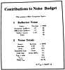
Noise Budget
|
|
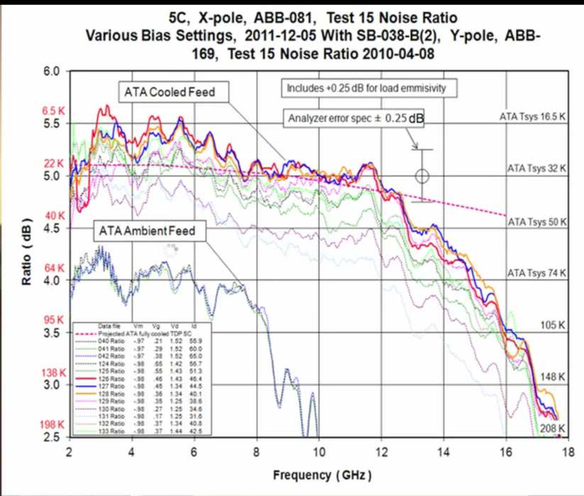
Proposed Antenna Cooling Upgrade - Mar 21, 2012
A big e-mail of corrections/enhancements from Matt Dexter
Matt also supplied these two lovely data flow diagrams in .pdf format that are
easy to view - to aid understanding. Each is about 135 KBytes can be magnified by your brouser for easier viewing. :-))
- MDexter_fx32_iBob_single_2008sep18.pdf
- MDexter_fx32_iBob_2008sep18.pdf
Thanks for writing
I *almost* have a picture of you at
http://casper.berkeley.edu/team.php ;-))
----- Original Message -----
From: "Matt Dexter"
To:
Sent: Thursday, September 18, 2008 4:19 PM
Subject: trip report and struggling on with ATA
> Hi Ed
>
> I just came across
> http://ed-thelen.org/ATA/HatCreekATA.html
> and wanted to congratulate you on a great write-up.
> Well done!
>
> If I may offer a minor correction or two...
or many more ;-))
> I think your "mixers" are called RFCB or Radio Frequency Converter Boards.
> And those aren't low pass filters @ http://ed-thelen.org/ATA/Mixer-03-.jpg
> Those are actually bandpass filters.
Probably very true, a DC component, bias, is probably worse than useless.
:-|
> The F3dB [3 db down?] of those BPFs is about 15.2 GHz -> 15.8 GHz .
> The allen head screws get hand-tuned on a network analyzer to define the
> filter response. Not easy for beginners to get right.
I interpret "F3dB" to be a 3 dB down corner frequency [of a filter]
(I had to take filter theory twice, didn't do so good the 1st time ;-((
> The signal path is :
> upmix the entire signal received over the fiber with the 4 different
> programmable LO1s ->
> filter with ~ 600MHz wide bandpass filters ->
> down mix with fixed LO2 = 14.9 GHz ->
> 600 MHz bandlimited output is now 329 -> 929 MHz
for those even more shaky than I,
LO = Local Oscillator
> 600MHz bandwidth is too expensive to handle in our current digital signal
> processors so there is a 529-729 MHz BPF on every output of the RFCBs. If
> you have eagle eyes you'll see them in
> http://ed-thelen.org/ATA/TechieWiringHeaven-.jpg
"Eagle eyes", and knowing what to look for ;-))
> Thus, the analog signal into the iADC+iBob plates, as Andrew discussed
> is actually a well defined band 529-729 MHz. And only the center 100 MHz
> is processed by the current correlator and beamformer backends.
>
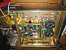
> This picture is mislabled.
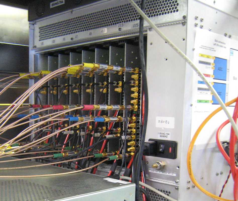
> http://ed-thelen.org/ATA/SETI-Processors-.jpg
>
> Those racks are for the fiber optic input, LO, sample clock, 1
> pulse-per-second generation and distribution, network infrastructure,
> support computers. The SETI Prelude racks are deep blue in color, sealed
> up (for airflow) and located just to the left of the racks in the picture
> above.
> Regarding
> http://ed-thelen.org/ATA/HatCreekATA-StrugglingOn.html#BerkeleyOct22
> Our current FPGAs could not fit the interpolating filters to get
> to delay steps finer than the 838.8608MHz sample clock resolution.
> Just not enough gates. 1/838.8608MHz is as fine of delay step
> as is supported at the moment.
>
> At this time only the FPGAs programmed for the Transient Search, aka Fly's
> Eye, experiment have fine channel gain correction on the 8bit I + 8bit Q
> voltage samples just after the digital down conversion. The FX correlator
> has gain correction on the F engine's output 1024 spectral channels which
> are 4bit I + 4bit Q voltage samples.
>
> The attachments may, or more likely - not, help explain part of the
> signal flow.
>
> all the best,
> Matt Dexter
|
|
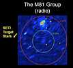
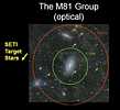
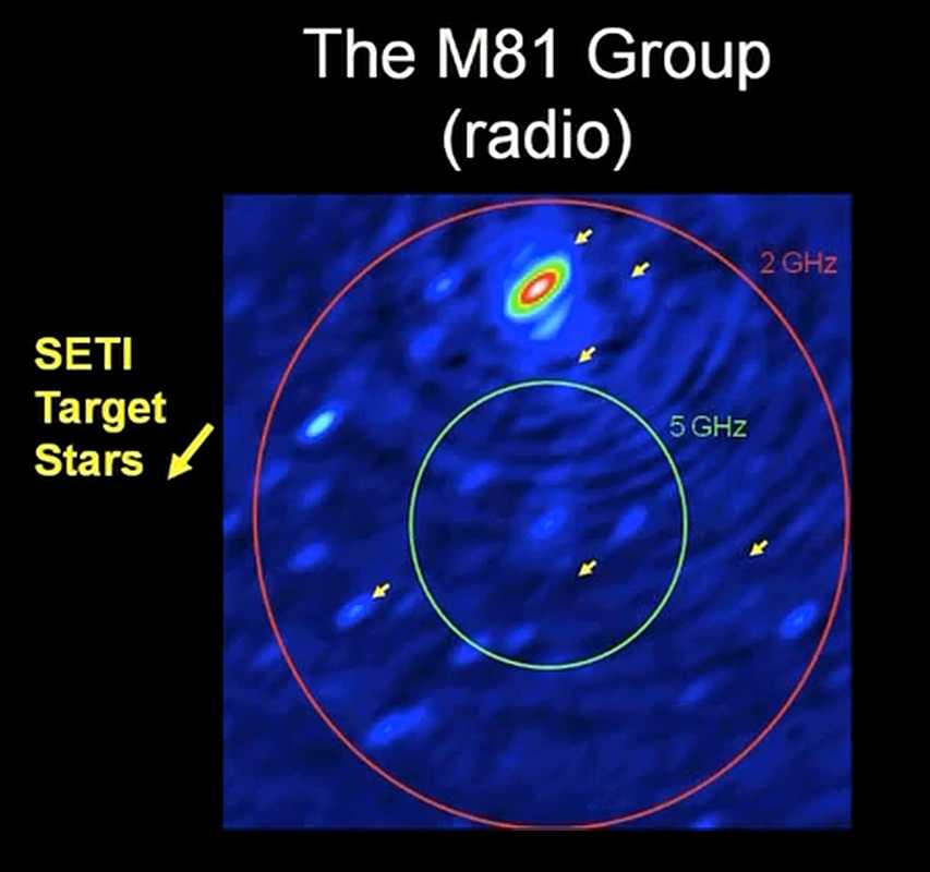
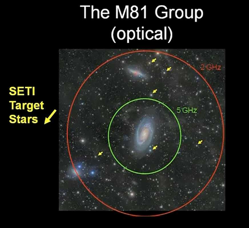
An Illustration of Multiple Target capability
Images from the SETI web site.
|
A single large "dish" can really only focus on one point in the sky at a time.
It is my understanding that an array of horns/di-poles/... near the focus
is very little used.
A disadvantage of an array of smaller "dishes" is that
a surprising amount of very precise variable time delays are required,
in a central building, to merge (correlate)
the results of the multiple antennas into a very much smaller beam width
than is necessary for a single large "dish".
However, repeating the the electronics in the above paragraph, allows other objects in
the wider beam widths of the small antennas to be examined at the same time -
just repeat the electronics in the central building, one more time for each target.
The following images attempt to demonstrate this feature.
- Note the labeled red and green circles - the higher the frequency,
the smaller the beam with of a given antenna.
- The six yellow arrows point to selected targets - within the beam width of that frequency.
"All" that is required is six times the times delays and correlators in the central building.
|
| |
|
Polarization Rotates during tracking when using altazimuth mounts
As the earth rotates, the apparent polarization of the "target" changes
- what had been "vertical" polarization, slowly changes toward "horizontal" polarization
- same effect in optical images
- altazimuth mounts
Since the sensors don't rotate, you must rotate using "software", changing the ratios of
the local "vertical" and "horizontal" RF polarizations coming in from the antennas.
- Altazimuth mounts give a Horizontal Coordinate system instead of Equatorial coordinates
of the equatorial mount.
-
Horizontal_coordinate_system shows this coordinate conversion.
|
My continuing struggles to understand
|
HatCreekATA-StrugglingOn
Berkeley Technical Memoranda
Pointing/tracking the Synthesized Beam "Array"
Information Please
Article SETI OBSERVING PROGRAMS ON THE ATA
from "SETI INSTITUTE Explorer" Second Quarter 2008, Volume 5, Number 2
Adding new finds here, as of June, 2008, new stuff near top (here)
Interesting search keys
BEE2 beam
Interesting web pages
My Understanding
|
an integer delay unit? (fractional is tougher) and if the electronics aren't fast enough
(ATA wants 800 megahertz) you can run n units in parallel phased. Not easy to get 350 x n
physical units synchronized when the period has a wavelength of 0.37 meters !!
|
|
Maybe we can understand their technique of delaying the signals of each antenna to make 16 independent beams.
(These 16 beams must be:
- with in the 5 degree beam width (at 1.4 gigahertz) of each 20 foot reflector
- (the focus bandwidth on the log periodic sensor is very broad also - max 20% down from nominal),
adjusting the delays to allow for
- the desired angles of very narrow phase generated beam
- the earth's rotation moving the phasing of each antenna with respect to all others
- the location of each telescope
- the pointing vs delay offset of each telescope
- - the focus is not at the center post - hopefully antennas are identical and this normalizes out.
- drift in the length (transit time) of the fiber optic
- and a host of other effects.
Then of course there is:
The earth's rotation causes oblate spheroid and local gravity is partly "centripetal" force.
- - offset in "up"?, "down" does not go through earth's center, and tidal force of moon and sun
- doing SETI
I did some programs simulating 46 antennas
- randomly placed roughly in the area of the ATA,
- resolving power and in-field noise of out of phase sources
- making life simple by adding phases
Probably should re-do with:
Variables:
  a:   multiple random arrangements of antennas
  b:   multiple array areas
  c:   multiple frequencies

Techniques:
  a:   To compute power at various angles, use both
         - arithemetic average
       and
         - average of (sum of products of antenna pairs)
               45+44+43+42+41+ ... +1  = (N(N+1))/2 = 1035 pairs
Reporting
  a:   peak "gain"
  b:   assuming a rather flat average off axis response
              (verify)
       determine the ?power? db down from peak "gain"
|
External links: newest additions often near top
- Stolen "lifted" from
http://adsabs.harvard.edu/full/1974A%26AS...15..497M - added April 23, 2017
-
50 Yrs of Research at Arecibo Observatory added Aug 11, 2014
- an interesting "series" by Professor Ian Morison - added Jan 2013
- WOW Signal,
YouTube of Ohio State antenna "Big Ear" and Dr. John D. Kraus
-
Jill Tarter at TED discussing SETI
- ATA on SETI web site, and
more technical
- A GREAT RADIO ASTRONOMY course !! ( New Jersey Institute of Technology )
- Sidereal time to help point and phase the telescope.
- Gerry Harper Project Memos and Papers
- How Will ALMA Make Images?
- ATA as on ESO "80 Telescopes" in 2009
- - - (try to sleep through the 3.5 minute lead in music)
- The Planetary Society
- - -
How radio telescopes get "images" of asteroids
- Optical
-
How Big Are Those Killer Asteroids? A Critic Says NASA Doesn’t Know. from Allen J. Palmer.
(local .pdf)
- Keck Observatory ( with tour ;-))
| Yes, Kevin McCann is the director of software development on the
Keck telescopes. The Keck was the first telescope to use a segmented
design. Building a 10 meter mirror would be too heavy, too costly and
take too long to cool down.
To keep the hexagonal mirror segments aligned, they need to keep the
edges within lambda/10 (or about 10 nm). They use capacitive edge sensors
(6 of them per mirror) and three actuators (three degrees of freedom)
per mirror. Control is done about twice a second. Loads on a segment
is distributed through a "whiffletree" (look it up in Wikipedia!).
Of course, moving one segment requires moving all the others too to
keep all edges aligned. Becomes a convolution problem (a bit like the
CD control in Measurex systems :-)
We (NI) are working on that problem with the EELT. They'll have 1000
segments (versus 36 in the Keck). That makes the control problem a
3000 (actuators) x 6000 (sensors ) array multiplication mess. Which
they want to do in a millisecond! But we are doing it using a 64 core
Dell server and LabVIEW. This is called "active optics" (not to be
confused with "adaptive optics" for atmospheric turbulence compensation).
What was also interesting in the Keck is how they got the mirror segments
polished to the right shape. It would be impossible to have an off-axis
segment polished to a perfect hyperboloid. The way they did it is to
pre-stress a circular mirror, polish it to a perfect spheroid (easy)
and then let it relax. If all the computations were correct, after
relaxation the shape became a hyperboloid. Worked like a charm.
Dirk De Mol
National Instruments
|
-
Phasing The Keck Telescope
- Thirty Meter Telescope Mauna Kea
-
"Lick Exoplanet Search" - Steven S. Vogt (SETI Talks) -
The Lick-Carnegie Extrasolar Planet Search Program ... Doppler-based planet survey.
- Minute 18, size of the effect, about 1 part in 100,000,000 - calibration issue !!
- iodine reference - excellent discussion of detection method !!
@ 37 minutes, 2004 upgrade to < 1 meter/sec
@ 45 minutes, new specialized 2.4 meter telescope next to the 3 meter on Lick. and results
posted Dec 2009
|
Some of my YouTube ATA favorites, June 2016
On YouTube, searching for
SETI ATA
some of my favorites, "no particular order"
|