Debugging Computer History:
My Summer with the Atanasoff-Berry Computer
Charles S. Shorb
SAS Institute Inc.
Charles.Shorb@SAS.com
Abstract
"Talent hits a target no one else can hit: Genius hits a target no one else can see." - Arthur Schopenhauer
1. Personal Background
When I came to Iowa State University (ISU) in 1992, I had the usual understanding of the history of the computer; in the late 1970s people began taking increasingly smaller components and packaging them into a form that resembled modem desktop computers. My father was an early computer enthusiast, so I was fortunate enough to get my first computing experience on a Radio Shack TRS-80® Model 1. I thus can confess, with a certain amount of pride, that I was interested in computers before IBM created the PC nomenclature with the advent of the Model 5151 PC. Beyond this, I had a vague notion of a mildly interesting collection of overly large machines that predated the PC. These machines continued some linear progression towards the important achievement of personal computational devices with which I was familiar.Mechanical skills would play a significant role in the ABC debugging project. This is an area in which I have always been fascinated. In my youth I would often dismantle objects to gain a better understanding of how they functioned. My sisters still complain that my disassembly rate was higher than my reassembly rate. My success at fixing broken items was enough to keep them (mostly) satisfied. My father also played an important role in my mechanical knowledge by providing cars that were old enough to require frequent servicing opportunities.
2. Who was John Vincent Atanasoff?
Who was Atanasoff? What was his role in the history of the computer? All I knew, as an undergraduate, was that he was someone that supposedly had a part in the invention of the computer. I know this because it was mentioned with pride in the mandatory introductory Computer Science course at ISU, and there was a wall mural describing Atanasoff and Berry in the main entrance m the Physics Building. At the time, this name was more important to me as the name identifying the building that for the next couple of years would house the bulk of my classes. I remember joking, with the impertinence of youth: "The only way to survive Jack Lutz's Discrete Computational Structures class is to work your 'atanasoff'."With a name like Atanasoff, you have to expect this.
3. The Project
It was almost ten years ago when John Gustafson, founder and lead principal investigator of ISU's Scalable Computing Laboratory (SCL), called me to his office to ask if I would be interested in helping with "a project." The ABC replica had been brought to the point of cosmetic completeness; it had all the right parts. The replica was just not ready to perform any computations. A committee had proposed a budget for a team to bring the machine to a working state. Gustafson proposed that a single person could accomplish this in a third of the time and budget. Gustafson then informed me that I was the person he had in mind to accomplish this task. I have a fuzzy recollection of a significant passage of time before remembering to shut my mouth, which was affixed in an incredulous "O". I then could only stammer out a simple "Sure." Gustafson then handed me the definitive technical source in order to prepare: Alice and Arthur Burks' book The First Electronic Computer The Atanasoff Story [1]. I would suggest this as mandatory reading material for both the functionality of the machine and a rudimentary history of the trials and tribulations of the ABC.In the years of controversy that followed the court case over who invented the computer, Atanasoff stated, "There is plenty of credit to go around." I agree. My main contribution to the replica project was being a graduate student; I was young enough to devote too many hours in a windowless basement, happy to work for little pay, and able to exist on Coca-Cola® and Hostess Fruit Pies®. Nothing could have been done if the replica did not already exist. There are numerous people to thank for this accomplishment, including: Skip Derra, Jennifer Augenstein, John Erickson, John Gustafson, Alvin Read, Gary Sleege, Harold Skank, Jeff Etringer, David Birlingmair, Del Bluhm, Joel Snow, Terry Herrman, and Jerry Musselman.
For the task of debugging the replica, I relied on: Gary Sleege, the definitive source of electronics expertise; John Erickson, who provided tireless physical help and begged, borrowed, and (perhaps) stole any needed vintage parts; Charles Wright, who provided electronic test equipment from the Computer Engineering department; Guy Helmer, who did an excellent job completing the rewiring task; Quinn Snell, who was put to work every time he poked his head in the door; and John Gustafson, who took care of all administrative tasks and dropped in frequently to ensure I was still vertical or at least still breathing.
4. The Atanasoff-Berry Computer
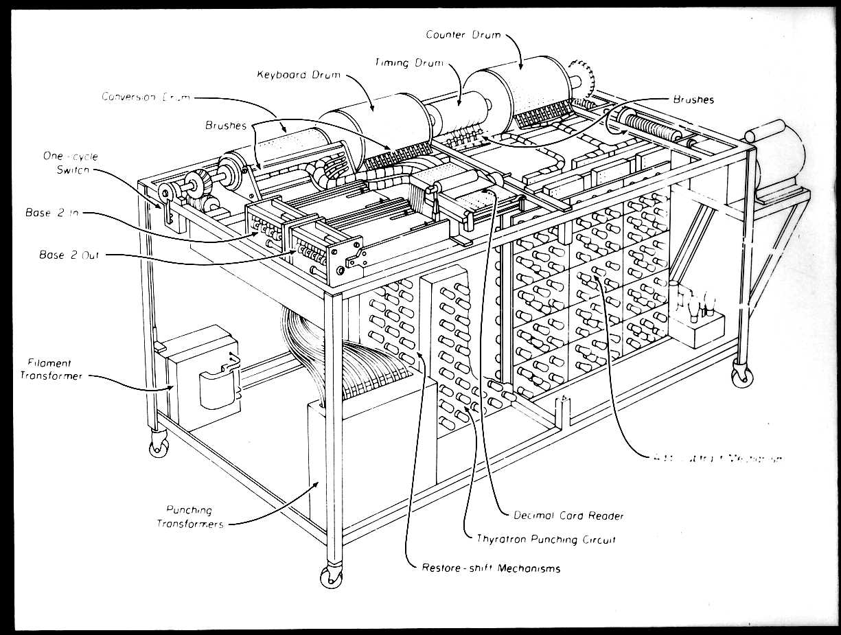
Figure 1. The Atanasoff-Berry Computer [2]
My initial reaction to the ABC replica was one of pure amazement and incredulity. I was simply stunned at the genius employed to accomplish the economy of size of this machine. I was always led to believe that the first modern computers filled entire rooms with vacuum tubes counted in the thousands. If this was some smaller proof-of-concept it should have been a massive ball of jumbled wires, vacuum mbes, flashing bulbs, and a Jacob's ladder shooting sparks into the air. I was witness to something that simply did not fit the traditional historical model of a computer: the ABC was elegant, well designed, and complete. Perhaps the size of the ABC alone causes most detractors to continue their disbelief; it is simply too small and too perfect to fit the model of a vintage computer. Although still too large to be called a laptop, compared to other early computers it certainly could be described as "mini."
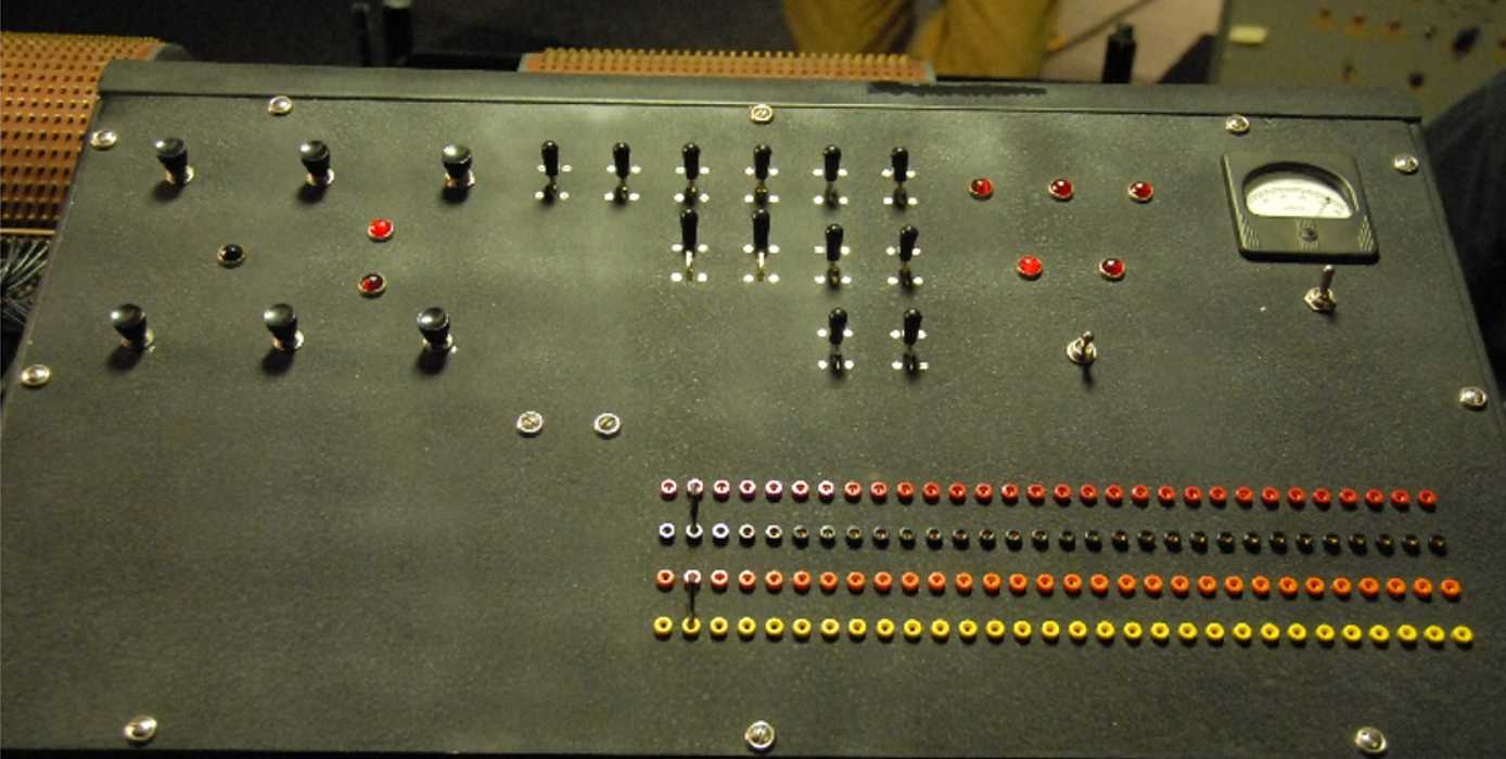
Figure 2. The ABC Control Panel
The operator control panel is located at the front of
the ABC. This is an all black panel with a variety of
buttons, switches, coefficient selection slots, and one
power gauge (for measuring the +/- 120 volt busses).
The operators task was chiefly of directing the 1/O
operations to load the memory drums. Once
accomplished, it was merely a matter of activating the
go button to start the process of coefficient elimination.
Immediately to the left of the operator console was the Base-10 input/output tray. This was designed to accommodate a standard IBM punch card. The IBM punch card would encode up to five base-10 values. Brushes ride above the card and make contact with pegs underneath through holes punched in the card. The reader would move once per cycle (with a satisfying clank) to encode the next power of ten represented on the card.
The base-2 to base-10 conversion was accomplished with an odometer attached to the Base-10 tray. The odometer was similar to a car odometer, a cylinder composed of individual wheels or dials. Each dial represented a separate power of ten. Each power of ten was subtracted from the selected coefficient. If it did not change signs, the count on the odometer was incremented. When the coefficient was reduced to zero, the base-10 number was represented on the numbered dials of the odometer.
The left side of the ABC has two trays. These are the Base-2 input/output readers. The nearest is the Base-2 Input reader. The electrodes for the reader are somewhat broad (they look like a new pencil eraser) whereas the writer electrodes are sharp like toothpicks. Writing was a process of shooting sparks through paper m create a lower impedance path that could be detected by the reader.
The left-most drum along the back of the ABC is the Base-10 Conversion Drum. It has a copper appearance with pegs set at intervals that appear to define three sets of inverted triangles across the cylinder face. The appearance is similar to a music box cylinder, whose pegs activate the appropriate metal strips to reproduce music when rotated. If you place your ear close to the Base-10 Conversion Drum, although not a tune, you can hear the brushes as the pegs pass, increasing in volume with the increase in number of pegs as the drum rotates.
The next two drums are memory drums. These are notable for having a uniform series of brass pegs around most of the drum. These brass pegs represent one-bit of storage (internally each peg was wired to a capacitor). The left memory drum was named the Keyboard Abaci (KA), whereas the right memory drum was named the Counter Abaci (CA). The KA drum coefficients were successively subtracted from the CA drum until the specific coefficient changed sign. The contents of the KA drum would then be shifted right (divided by two) and the procedure was repeated using addition. This process continued until the specified coefficient was reduced to zero.
In between the memory drums is a series of copper rings or commutators. The commutators were active during the blank portion of the memory drums and were responsible for controlling the operation of the ABC.
Along the right side was the Carry-Borrow Drum (CB). The CB was a smaller drum that had only four contacts for each of the thirty coefficients. Internally each of these four contacts was wired to the same capacitor. This provided the 1-bit of carry required for coefficient processing.
Banks of modular vacuum tube assemblies dominate the front of the ABC below the operator controls. Each of these is an Add/Subtract Module (ASM). Each ASM took input from the KA drum (or Base-10 Conversion Drum), the CA drum, the CB drum, and the Add/Subtract Control circuit. Each ASM produced a sum bit and a carry bit. The sum bit was returned m the CA drum and the carry bit was returned to the CB drum for input to the next bit computation. Only fifteen of the thirty ASMs are visible from the front, the remaining fifteen are mirrored directly on the rear of the same mounting posts.
To the immediate left of the ASMs is a boxed unit of thyratrons, used to control the firing of the Base-2 writer electrodes. The transformers for the Base-2 are located just m the left of this unit.
Behind the Base-2 thyratrons is another boxed unit. This housed the KA Shift circuitry. Next to which was a collection of modular units having a variety of vacuum tubes and relays. This was the remaining computational control circuitry.
5. Beginning
The first task was to move the ABC replica from the Metals Development Building to a basement room of Spedding Hall. This task was made easier by one of the very few differences that the replica had versus the actual computer; namely, it was narrow enough to fit through doors. In about 15 minutes the ABC was sitting in its home for the next few months. At minute 16 of the project I had exhausted the entire scope of my pre-planning procedures. I was left in a room with a replica of one of the most important works of the 20th century without a clue as to how to proceed. I took a deep breath and did what I believe any good engineer would have done; I broke for a snack. This ritual was repeated on many occasions. Much like Atanasoff and his jaunt to an Illinois roadhouse, it was a chance to let my mind work on the problem. How could the current data be interpreted? What data was missing? What tests could be run to further understand the issue? Every waking moment was spent pondering how the machine was supposed to work, what it was doing, and how to reconcile the differences. Particularly vexing problems would require the much longer walk to the vending machines in the old train depot; otherwise the machines in the much closer physics building would suffice.After returning from my requisition of almost pure carbohydrates, I started with the one element for which I knew the expected output: the power supply. I was under the assumption that having the correct voltages was a good place m start. This was to be the first of many non-fatal and fortunately not overly destructive errors. A flick of the power switch produced an intense humming sound followed very quickly by a waft of gray smoke. I quickly shut the power supply off. A quick inspection determined that there was a short in the 6.3 volt AC filament heater bus. The brief seconds of power were enough to begin baking off the plastic coating on the wire.
The short was found to be a simple wiring mistake. The hot and ground wires were crossed on one panel of the Add/Subtract Modules. The replica was constructed to be authentic and did not necessarily follow current safety standards. Most wires on the entire machine were black. The wires for the vacuum tube heater elements happened to be green, both for live and ground. This discovery was a good reminder that the design and implementation might vary outside of normal operating specifications.
One classic myth associated with vintage computers was that they always had flashing lights. After fixing the vacuum tube heater short, the power was reapplied. Apart from a small glow from these vacuum tube heaters, the machine remained (somewhat disappointingly) dark. Eventually when the machine was put into action, thyratrons used for the flip-flop circuitry controlling the Add/Subtract operation would glow with a wonderful purplish hue. Thyratrons were also used to control firing of the base-2 card output electrodes. When writing a 1-bit, the thyratrons would create a spark of purple fire. There was a rumor (never substantiated) that before leaving for a rest, it was customary to turn off all the lights in a particular Spedding Hall basement room to appreciate this fireworks display (witnesses would still be bound by their promise of secrecy).
Apart from the initial mistaken wiring, I do not recall finding any further schematic variances except some trivial terminal numbering, which were minor inaccuracies that did not affect functionality. Unfortunately the only remaining wiring issue would be very time-consuming to resolve. A decision was made to depart from historical cloth wiring and replace this with coaxial cable. In the rush to meet a public showing deadline, the ground wire for the Add/Subtract Modules input and output wires was quickly soldered. This melted the coaxial cable center shielding, creating shorts. A few faulty wires aren't a large problem, perhaps even expected. A mass of wires that produce shorts with simple jostling was unacceptable. The input and output for each Add/Subtract Module had to be ripped out and rewired. This "improvement" on the original design turned out to be one of the largest consumers of time on the project.
The reconstruction main has my utmost respect. I do not blame them one bit (pun intended) for the shorts in the coaxial wiring. The Add/Subtract Modules wiring just happened to be one of the last items to be finished. The team did an excellent job meeting a strict deadline. Given similar constraints I would have produced similar results. This was proven during rewiring. Even with great care a connection would have to be removed, cut, and rewired to resolve a short. The process became a wire-by-wire challenge: solder connection; attach test leads; jostle wire. The multi-meter continuity alarm was not an unexpected, though uninvited, announcement of more rewiring work.
6. Commutators
Unless your work involves electric motor design, a commutator is not likely to be a component on any electronics schematic. In all honesty, I had no idea what a commutator was. John Erickson was kind enough not to snicker (too much) when he pointed out the copper rings between the two memory drums. These copper rings rotated with the memory drums to provide control over various aspects of the computation.When the machine was assembled, the commutators were installed in their original copper ring form. In order to provide correct timing inputs to the control circuits, these rings had to be removed and teeth cut or grooves made. One of the memory drums had to be removed to allow removal of the commutators. The memory drum drive shaft was just soft enough for the setscrews of the memory drum to create grooves. After several failed attempts, removing the memory drum became an all-out tug-of-war between Gustafson and me. Gustafson specifically told me I'd better get the rings cut right the first time; neither of us wanted to repeat the process.
The physics machine shop foreman was happy to create a mold for the rings. He gave me an introduction to the milling machine (also not taught in my computer science curriculum) and then turned me loose. While I was watching copper slowly disappearing as rings were transforming into commutators, I realized that this was my first venture back into the world of 1938. I imagine that Sleege felt this way when watching his research transform into schematics, or Erickson watching vintage vacuum tubes become Add/Subtract Modules.
The commutators were my unique contribution to the reconstruction project. I created 11 of the 12 commutators; one was already milled prior to my involvement. During debugging I had to adjust, move, and sometimes hand file these to match a particular timing requirement. I'm proud of those silly copper rings. It was convenient that the rings had a similar count as the letters in my name. (A close examination of these rings will find an encoding of my name upon them.)
7. Debugging
From the beginning I trusted the design "as-is." Atanasoff and Berry did an excellent job of thinking through the specifics, and Sleege was thorough in his research and extensive knowledge of electronics.I did spend a couple of days resolving a very large clank that would always occur the first time the ABC was turned on. The Base-2 Card Actuator would trigger during the initial `boot' process. Without adding additional parts I was able to resolve this issue with prudent use of the current relays. I remember proudly proclaiming this to Sleege as I showed him a drawing of the new schematics only to have him state the One-Cycle Relays were among the circuits for which they had the actual schematics. I had unwittingly made the machine less authentic. Personally I would like to believe that both Atanasoff and Berry would have approved of this improvement. I also imagine that they simply put up with the noise as they worked to resolve more important matters. I certainly kept this in mind as I begrudgingly rewired the circuits to their original design.
The entire process of debugging the machine from this point forward could be summed up as follows: attempt to perform a specific task; watch the task almost function; scratch my cranium in an attempt to instantiate a rational thought process; admit a clue was not in my possession; make a trip to the vending machines; and return with at least one idea to try.
Debugging the ABC was all about voltage. If the correct voltage was not where (or when) it should be, it was a matter of determining the cause. Gustafson still chides me that I became an expert at determining, by feel, the differences in the various bus voltages. I recollect those jolts as constant reminders that a multi-meter was far superior at performing these calculations.
Most of the remaining wiring problems were resolved with a change in capacitance or resistance. The remaining tasks were to ensure that brushes were in precise position to touch what they should be touching, and to avoid what they should not. (It is interesting to know that IBM still sells these brushes. If I remember correctly the IBM part number was originally 202. That same part number today is 00000202. For personal interest I asked the operator how many of that part number IBM still had. She "could not divulge this information." Apparently, the amount of stock-on-hand is a corporate secret.)
I believe it is a safe assumption that the original ABC had a removable handle to manually rotate the driveshaft. This handle was one of the more useful and less recognized advances in modem computers, the ability for the debugger to single step through a computation. This ability more than anything else allowed for precise adjustment of the brushes against the memory drums and the minute adjustments to the commutators. Gustafson stated this succinctly as tuning, similar to that done to a piano.
It wasn't much of a surprise when the machine finally began to correctly calculate small systems of linear equations much like it did back in the early 1940s.
8. Solving Equations
It was the operator's task to correctly load the problem into the memory drums; perform the computation; and manage the temporary store of partial computations. This was made even more difficult with unlabeled switches and lights on the control panel.An IBM punch card could encode five decimal values. These were loaded one card at a time onto the CA drum. The top six switches on the control panel were used to direct the IBM card values to the appropriate set of columns on the CA drum. The CA drum values are then transferred (via a button on the control panel) to the KA drum, the CA drum cleared, and the process repeated.
Once the equations were loaded onto the CA and KA drums, the coefficient to be eliminated was selected. This was done via insertion of two jumpers into the respective column of holes on the front panel. The top row of holes was used for coefficient zero detection, the bottom for detection of change in sign. The process of coefficient elimination was then started with a press of a button. A light on the front panel would illuminate m show activity, when it turned off the process was complete. The current set of equations with the eliminated coefficient was now located on the CA drum. For large problems this would then be output to the Base-2 writers for future eliminations.
One question that often arises is how large were the equations that we solved on the replica. We solved two equations with two unknowns. (The entire process can be viewed at the ABC Web site [3].) There were two unresolved issues that prevented solving larger systems of equations. First, the summer ended without finding the appropriate type and weight of paper. Second, the electric motor, was too advanced. The replica motor would synchronize with the rising or falling cycle of the 60 Hz AC power. The original motor would reliably synchronize to only one cycle, which was required for correct triggering of the base-2 I/O.
9. Deus ex Machina
The more I came to understand the ABC the more I realized how technologically advanced this machine was. Every aspect of the ABC is nothing less than a work of art, a tribute to the genius of Atnnasoff and Berry.I was first impressed with the size of the ABC merely because it did not fit the historical model of early machines. To know that this size is a result of careful and thoughtful design is amazing. The process of base-10 conversion is an excellent example of the overall engineering for economy of size. Instead of designing a separate module for conversion, the solution was to change the input source from the RAM (memory drum) to use the ROM (Base-10 Conversion Drum). Thus the input was directed through the Add/Subtract Modules similar to normal computational processing.
The Base-10 Conversion Drum is an engineering marvel. Simply adding this 'ROM' to eliminate human decimal-binary conversion is impressive. The recognition that the drum could be greatly compressed in size is brilliant. The Burks' book [4] provides an excellent overview of this technical achievement.
The Add/Subtract Modules were built with seven dual triodes. The circuit was designed to require thirteen triodes, effectively leaving one triode unused. This allowed each Add/Subtract Module to be removed from the machine and tested singularly, a benefit far outweighing the "wasted" triode. These Add/Subtract modules are known today as "full adders." They are still taught as fundamental building blocks of modem computer architecture. All of the Add/Subtract Control, One-Cycle Relays, Shift Control, and Negative Number logic were modular. The ability to remove these components and rest them separately saved countless hours of debugging.
Detractors deride the use of mechanical components in the ABC. I agree that an ideal solution would have been entirely electronic. One fundamental principle of engineering is the balance between the ideal and the practical. I believe that Atanasoff recognized both time and monetary constraints to a fully electronic solution and came up with an elegant design. This is the same principle used in modem computers with their mechanical secondary mass storage devices (also known as Disk Drives). It is important m recognize that the mechanical components of the ABC merely provided timing and I/O, just as mechanical parts do in present-day computers. The ABC was the first fully electronic, Boolean logic computer. This was a complete paradigm shift from the mechanical gear calculators of the past.
10. Who was John Vincent Atanasoff?
(Revisited) Who was Atanasoff? What was his role in the history of the computer? John Vincent Atanasoff was the man responsible for inventing the modern computer. I know this because it is a historical fact that has withstood the test of physical evidence in the patent trial. I have been extremely fortunate to witness his genius once again come to life during the reconstruction project. The principles he used in his 1940s marvel are still in practice m this day. I unfortunately never had an opportunity to meet Atanasoff. I have had the wonderful fortune of meeting Alice and Arthur Burks, as well as John Atanasoff II, and other family members. Everyone has the same story to tell of Atanasoff: he was indeed a man that hit targets that no one else could see. With a name like Atanasoff, you have to expect this.References
| [1] | Alice R. Burks, and Arthur W. Burks, THE FIRST ELECTRONIC COMPUTER The Atanasoff Story, The University of Michigan Press, Ann Arbor, MI, (1988). |
| [2] | "Reconstruction of the Atanasoff-Berry Computer (ABC)." Scalable Computing Laboratory. January 22, 2003. http://www.scl.ameslab.gov/ABC/Progress.html. |
| [3] | "Reconstruction of the Atanasoff-Berry Computer (ABC)." Scalable Computing Laboratory. January 22, 2003. http://www.scl.ameslab.gov/ABC. |
| [4] | Alice R. Burks, and Arthur W. Burks, THE FIRST ELECTRONIC COMPUTER The Atanasoff Story, The University of Michigan Press, Ann Arbor, Ml, (1988), pgs 52-57. |