Table of Contents
- Notes from phone conversation with Dr. John Gustafson Feb 3, 2010
- E-mail from Charles Shrob Feb 3, 2010
- Latest ISU JVA/ABC Greetings Dr. Carl Chang, Feb 3, 2010
- John Gustafson in http://www.johngustafson.net/pubs/pub57/ABCPaper.htm
- operator sets up rotors
- The ABC “Instruction Set”
- Gaussian Elimination - Pseudo-Code
- Another view of 'Specialized 'Computers''
- the later more general CORDIC algorithms
- Overflow Detection?
- Current location/status of ABC March 30, 2010
- Resistor Selection May 29, 2010
- Fun with vacuum tubes, 6C8G June 3, 2010
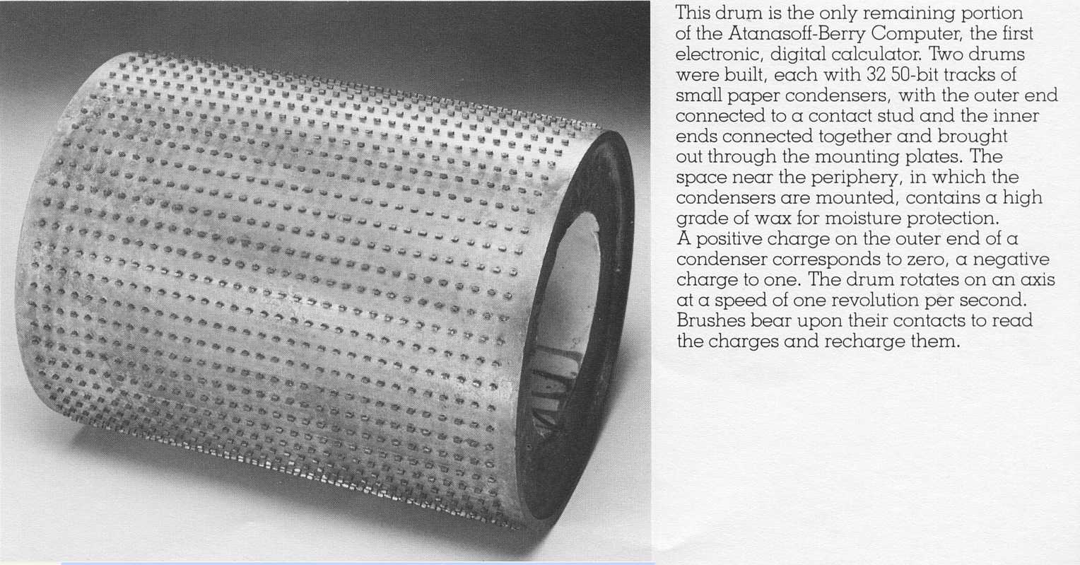
- Picture of original drum memory - Sept 15, 2010
==================================
Notes from phone conversation with Dr. John Gustafson Feb 3,2010
============================================================
E-mail from Charles Shrob Feb 3, 2010
By far the greatest reward in my involvement with the ABC project was meeting so many fine individuals; Alice and Arthur Burks were great!
- coefficients were loaded five at time in parallel. On the operator console there were a series of 6 pull down levers that were hard wired to the input of the corresponding Add/Sub modules Thus the output would be correctly directed to the appropriate 'rows' on the CA drum. (interesting thought experiment: I never tried output to multiple banks simultaneously. I can't think of why this wouldn't work and would be a good way to have redundancy.)
- Along the base of the operator console there are 4 rows of female banana clip holes. These correspond to active/ground pairs for each of: coefficient elimination select and zero detection. Coefficient detection was wired to a commutator (copper control ring in between CA and KA drums). This checked for most significant bit overflow, which enabled the shift/reduce logic and toggled the add/subtract logic. The zero check was hard wired to a relay that was reset for each cycle. Any 1-bit would deactivate the relay signaling anther cycle of coefficient reduction was required!
- the algorithm worked by eliminating the given coefficent by successive subtraction/Addition. When zero was crossed (determined by overflow on the MSb position) the KA drum was shifted right one bit (divided by two) and the operation was repeated from the opposite direction. This continued until the coefficient was eliminated.
- standard IBM punch cards were used for decimal input. These had rows of numbers 0-9. The coefficients were simply punched from the cards to represent the number reading from left-right. The base-10 reader was a piece of material with copper 'pads' for each of the punch cards possible positions. These copper pads were wired to the base-2 drum read brushes. The top of the reader had brushes (10 high, in 5 columns) that would read each of the 5 coefficients in parallel. These 'reader brushes' were routed (via front panel selector switch (described above)). The top of the reader ratchet across the card allowing each column of the base-10 input to be visited (once per cycle)
- intermediate (base-2) cards were simply a a dump of the CA drum values. Electrodes on the ouput would spark the paper (carbon scoring it) for each active bit location on the drum. Think of the CA drum being fingerprinted. Ink is applied and only stuck to (say) the 1-bits. This is then rolled on a piece of paper.
Please let me know how I can help you further!
Take care!
==============================================================
Latest ISU JVA/ABC Greetings Dr. Carl Chang, Feb 3, 2010
How wonderful to be able to know you folks - the real experts!
We at ISU are thinking of developing a more informative and interactive web
about JVA/ABC, including some of the latest developments such as the
upcoming exhibit of ABC in the Computer History Museum, the ongoing
development of IEEE JVA Medal, etc.
I hereby introduce
Laurel Tweed, our program coordinator,
to be in contact with you all. Oftentimes we receive inquiries about the ABC legacy,
including some technical questions which only you folks with definitive
expertise may answer.
Again, it is truly a pleasure to get to know you all and keep in touch!
Please feel free to visit us anytime.
Warmest Regards,
Carl
===========================================================================
My comments on paper
"6. A Stumbling Block: The ABC Mass Storage Scheme"
===========================================
operator sets up rotors
===================================================
7. The ABC “Instruction Set” - from
http://www.johngustafson.net/pubs/pub57/ABCPaper.htm
Maybe a good detailed picture of the operator's area would be very helpful.
Ed's Questions: as of Feb 27,2010
===========================================================
Gaussian Elimination - Pseudo-Code
Another view of 'Specialized 'Computers''
As I understand it the Eniac was basically 20 electronic decimal calculators with ability to wire in the passage of data between them and sequence through some steps. It was a major effort to make it calculate both e and pi to around 2,000 decimal places. They practiced on e and it took a weekend, and then they did pi over a 3 day weekend to a little over 2,000 places. (I think the Eniac had the ability to read and punch cards at the time; and I don't know if that facility was used in computing pi. I assume cards were the output?)
Programming the Eniac was a significant task. I suspect it was somewhat like instructing 20 "computers" (people who computed) using 20 calculators do the task. Except people were smarter, but less accurate than lots of plug boards and switches.
Anyway based on the dollars and number of people involved, the ABC wins, hands down, for elegance. Ed's ABC simulator should provide a very interesting insight to that elegance.
LaFarr Stuart
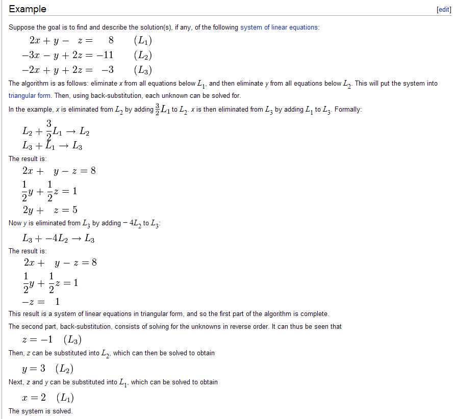
Wikipedia Example
The Later More General CORDIC Algorithms
The CORDIC algorithms were used 25 years later in the very successful HP 9100 Project
and the subsequent HP-35 pocket calculator - which was responsible for 1/3 of Hp's
profits for a few years.
Maybe some mathematical person could enlighten me if Atanasoff's algorithm is a subset of
the later CORDIC and/or in any way related.
A survey of CORDIC algorithms for FPGAs.
From Steven Winegarden - March 16, 2010
Hi Ed, LaFarr, ...
Overflow Detection ? in the ABC - answer from John Gustafson, March 27, 2010
Charles Shorb can weigh in here, but I'm pretty sure there was no overflow or underflow detection on the ABC.
Think about the desktop Marchant and and Monroe calculators of the era. What happened when you added 9999999999 and 9999999999 and got a number larger than ten digits? I'm guessing... nothing. You got the rightmost ten digits of the result, 9999999998, no complaints, no flags, no interrupts, just a bunch of dumb digits staring back at you.
It was up to the operator to leave enough margin in the scaling so this kind of thing did not happen, which is one reason Atanasoff probably put 15 digits of precision in each datum. Yes, there was a lot of "gut feel" in the scaling. Such gut feel was not uncommon back in the 1930s when people routinely had to scale problems for desktop mechanical calculators.
John G.
Arithmetic overflows in a concurrent (relay) machine, the Z3
The Z1 and Z3 (
Deutches Museum reproduction) did use floating point arithmetic operations. There was an overflow handling and a handling of the arithmetic exceptions. Overflow handling was very easy, it was one bit by the exponent.
...
Best regards, Horst Zuse
Arithmetic overflows in later machines
"It is apparent that, as the result of an algebraic addition
or subtraction of two quantities,
the sum or difference may exceed "computer unity" and overflow would occur.
The carry digit would be lost and the remaining digits
together with the correct sign would remain in rA.
The computer reacts to an "overflow" situation automatically. The
sequence of instructions is interrupted, and the pair of
instructions in memory location 000 is inserted. This insertion
is effected after both instructions of the original
pair have been executed even though overflow may have been
caused by the first instruction of the pair.
"If memory location 000 contains an instruction which
transfers control, a new instruction sequence is initiated.
It is important to note that, if no transfer of control is
ordered, the original sequence of instructions is resumed
after executing the pair contained in 000."
Current location/status of ABC - March 30, 2010
- ABC is now in Computer History Museum storage
Resistor Selection May 29, 2010
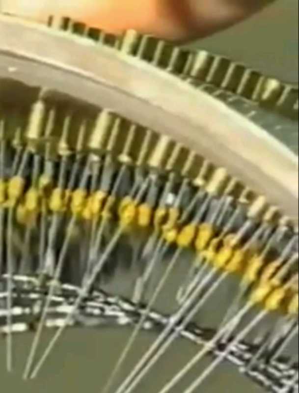
Seeing such lovely detail, one is tempted to get the tubes and resistors (and sockets
and other details) and go to work :-)) You go to your friendly electronics store,
but find most of the values of the resistors are unavailable. - No problem, they
must be out of stock, lets special order. No - these values are not the standard values
available from manufacturers. Well - no problem, have someone make them -
but the prices quoted for the special fabrication to say 0.5 percent accuracy cause
your jaw to drop - noo way !!
What happened?? What can we do??
What happened is that for most practical purposes, +- 10% accuracy is
actually plenty good, and the prices are "right", lots of volume.
If things are touchy about accuracy, +-5 and +-1% are available, at increasing cost
and decreased local stocking.
But above that, folks start to worry about temperature coefficients, drift during lifetime,
permanent change during overload or soldering, ... and other gooey details.
Now - is 1% good enough for our purposes for the type of tubes (6C8G triodes),
range of typical conditions, and drift during service life, and logic found in
the ABC ??
???
And is there a practical way to find if the combination of tube drift and resistor
drift will hazard the need for 100 percent system accuracy during the next run?
Since the machine has no accuracy checking during operation - the above question
seems interesting if the machine is to be placed into regular service.
A few years later, during WWII, effective, inexpensive diodes were developed which
made the Atanasoff touchy, difficult resistor matching obsolete. Diode logic has been used
in vacuum tube logic since the 1950s and continues in transistor logic today - 2010.
Fun with vacuum tubes, 6C8G June 3, 2010
Conservative Tube Operation
About 5 years after the ABC machine was abandoned, another
failure mode of (oxide coated cathode,
most low power) vacuum tubes
was identified - tubes in logic service, that had been held in an "OFF" condition for
long periods, got into a state where they would not conduct well when turned logically "ON".
From Google Books -
"Another problem with oxide cathodes is cathode poisoning. If the cathode is kept at full operating temperature, but little or no current is drawn, a high resistance layer of bariun orthosilicate is formed at the interface between the barium oxide emissive surface and the nickel cathode structure. This layer not only reduces emission, but more significantly it increases the noise resistance of the valve."
Charging and discharging the memory capacitors
Lets assume the output brushes are also in
proper alignment for the same time interval (2.5 milliseconds) a little later.
The 1/2 of the dual triode has 2.5 milliseconds to set the selected output capacitor to say
90 percent of its nominal value (about 3 time constants). We really have two circuits at work -
Worst case time constant (Tc = R times C ) would be 3x10^4 x 0.0015x10^-6 = 0.045 milliseconds.
Assuming a contact time of 2.5 milliseconds (from above) we get about 50 time constants,
well over the seemingly required 3 time constants :-))
The "Proof of Concept" machine adder/subtractor used 3 pentodes (5 element tubes) and 6 twin triodes
(three element tubes), the 6C8G.
The pentodes were replaced in the final machine by fewer twin triodes which reduced the tube count
by Clifford Berry (see
Atanasoff Oral History bottom of first page). I am guessing that:
Let us examine Clifford Berry's replacement of the (unidentified?) pentode as the memory capacitor
driver with the one section of the dual triode 6C8 (calling the tube a "6C8G" merely identifies
that the bulb is glass - this name was used later when some tubes used steel "bulbs").
Clifford Berry's suggestion and design was an engineering decision - although the
use of the pentode would provide a wider voltage swing on the memory capacitor (desirable),
the use of the triode section of the 6C8 would save tubes, filament current, space, and probably
money - and be sufficiently good. (Typical engineering that gives us economical products.)
I don't know the type of pentode tube selected in the 1939 "Proof of Concept" device, but the
6C6 was available in 1934 (RCA Tube Manual)
and a reasonable choice (and typical of receiving type pentode ) -
lets use the 6C6 characteristics.
Isn't this more fun than watching grown men, getting paid millions, throw and hit at baseballs?
I'm travelling this week; I'll try to answer from memory. Anything I don't recall will have to wait until next week when I can review my notes.
Charles
Dear Ed and Charles,
Carl K. Chang
Professor and Chair
Department of Computer Science
226 Atanasoff Hall
IOWA STATE UNIVERSITY
Ames, Iowa 50011
Ofc: 1-515-294-4377
Fax: 1-515-294-0258
http://www.cs.iastate.edu/~chang
Point 4 mentioned
If you "cooked" resistors in hot oil, the resistance could be forced
?downward? enough so that maybe the next pass would select them
into a more valuable 1% bucket. In anycase, selecting commercial 10%
resistors for 1% values is likely a lost cause
' operator sets up rotors
'  game plan
'    select two equations,  based on ??????
'      ( based on nothing ??? we start with 0 and 1)
'    we select coefficient 0 for pivot,   ???????
'      ( based on nothing ??? we start with coefficient 0)
'
'    find which coefficient is greater  in magnitude
'       set that into counter (Cntr)
'       set other into keyboard (KyBd) - to be added or subtracted from counter
'    choose starting operation by table
'       KyBd     Cntr      starting operation
'         +       +          -
'         +       -          +
'         -       +          +
'         -       -          -
' then DO it UNTIL
'       (the sign of the pivot Cntr changes)
'    or (Cntr becomes 0 or -0)  ie, no bit  change
'    ?or? (KyBd becomes 0 or -0)
' then
'     a)shift KyBd one bit right  (divide by 2)
'            (exit if KyBd becomes 0 or -0)
'     b) change operation, from add to sub, or sub to add
' END UNITL
' if here, the pivot coefficient has become 0 or -0
'     and time to store the coefficients for the next elimination
'
' if all remaining equations have a single non-zero something,
'       we are done with the ABC ?except for converting binary to decimal?
'
' ?? there is a promise of having to do a little desk calculator work
'    to get the final results??
The possible instructions, with approximate execution times, are as
follows:
Instruction (Ed's Understanding/questons)
as of Feb 28, 2010 Approx
Time in sec
Set short vector to coefficients 1 to 5
A decimal input card -an IBM card, 5 fields of 16 columns, sign & 15 digits,)
- ?? to which memory KA or CA ?? 1
Set short vector to coefficients 6 to 10
" "
Set short vector to coefficients 11 to 15
" "
Set short vector to coefficients 16 to 20
" "
Set short vector to coefficients 21 to 25
" "
Set short vector to coefficients 26 to 30
" "
Vector clear memory 1
memory 1 is CA 1
Vector copy memory 1 to memory 2
CA into KA 1
Read a short vector from the base-10 card reader into part
of the memory 1 vector, converting to binary using table
look-up and the add-subtract modules
memory 1 is CA
This seems a superset of the 5 "set" instructions at the top. 16
Read a short vector from the base-2 card reader into part of the memory 1 vector
?? which part??, memory 1 is CA
Why/how does a binary scratch card contain a short vector??1
Read a short vector from the base-2 card reader into part of the memory 2 vector
memory 2 is KA
Why/how does a binary scratch card contain a short vector??1
Select a coefficient in memory 1 (for elimination or decimal output)
memory 1 is CA, The operator inserts a conductive "C" clip into one
of the 30 appropriate hole pairs 1
Add or subtract (chosen automatically) one row from another to eliminate
the leading bit of the chosen coefficient, shifting right when successful
and stopping when the chosen coefficient is zero
"Successful" is a change of sign in the pivot column of CA.
100
Write a value to the decimal readout, using the lookup tables and
add-subtract modules to convert the base-2 value to base-10
which value, from I presume CA 100
- from http://en.wikipedia.org/wiki/Gaussian_elimination#Pseudocode
i := 1
j := 1
while (i <= m and j <= n) do
  Find pivot in column j, starting in row i:
  maxi := i
  for k := i+1 to m do
    if abs(A[k,j]) > abs(A[maxi,j]) then
      maxi := k
    end if
  end for
  if A[maxi,j] <> 0 then
    swap rows i and maxi, but do not change the value of i
    Now A[i,j] will contain the old value of A[maxi,j].
    divide each entry in row i by A[i,j]
    Now A[i,j] will have the value 1.
    for u := i+1 to m do
      subtract A[u,j] * row i from row u
      Now A[u,j] will be 0, since A[u,j] - A[i,j] * A[u,j] = A[u,j] - 1 * A[u,j] = 0.
    end for
    i := i + 1
  end if
  j := j + 1
end while
I love it. Your discussion highlights the "era". I think both Eniac and ABC were "specialized" computing devices. Neither had a stored program with the ability to modify the program and pass control to data read in.
Like Atanasoff's elimination algorithm, the later more general
CORDIC algorithms don't require a multiplication when evaluating trig and log functions.
They use only add, subtract and shift.
Thanks,
Steve
Ed,
Hi,
Apparently the ENIAC, the next electronic computer, did not have formal overflow checking either. The following
paragraph mentions that if adding a positive number to a positive number yields a negative number this
"indicates that the sum is off scale." There does not seem to be a latch or status to indicate that
the result is an error (not the actual positive sum).
OH - and more - The IAS machines - Illiac, Cyclone, Maniac, ... did not have hardware overflow detection either
- as per LaFarr Stuart
1.1.3. Representation of Digits by Pulses
"Because the counters in an accumulator are so connected that there is carry over not only from each decade counter to the one on its left but also from the 10**th decade counter to the binary counter for sign, the usual arithmetic properties obtain when complements are used in addition and subtraction. In this connection, it should be noted that even though, in the above discussion, we implied that sign P indicates a positive number and sign M a negative number, these signs may have another meaning. For example, if an accumulator holds P9 999 999 999, the carry-over to the PM counter which results when a positive number not in excess of 10**10 is added to this number, causes the accumulator to register sign M. Here the M indicates that the sum is off scale."
And even that sweet little LGP-30 computer designed 15 years later - the machine just HALTs
Now, about the UNIVAC (1) ?
From http://www.bitsavers.org/pdf/univac/univac1/UNIVAC_Programming_Jan53.pdf - page 83
"Sec. 2. Overflow Due to Addition or Subtraction
How soon we forget "The Goode Olde Dayze".
"Overflow.
Info from John Hollar, CEO of Computer History Museum
- Will be unveiled in the September or October 2010 timeframe
- Will be prominent in the new gallery "Who Invented the Computer?"
The Burke's book "" mentioned above, has an appendix with lovely schematics and details
such as the following:
from "The First Electronic Computer: The Atanasoff Story"
by Burks & Burks - courtesy of Alice R. Burks
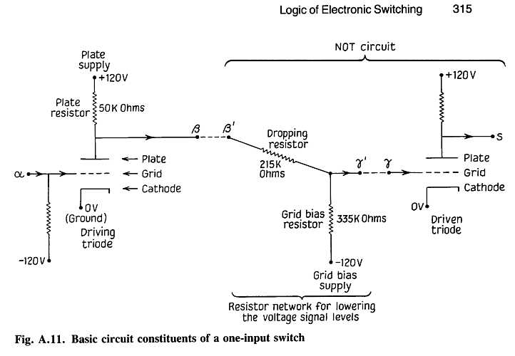
Fig. A.11
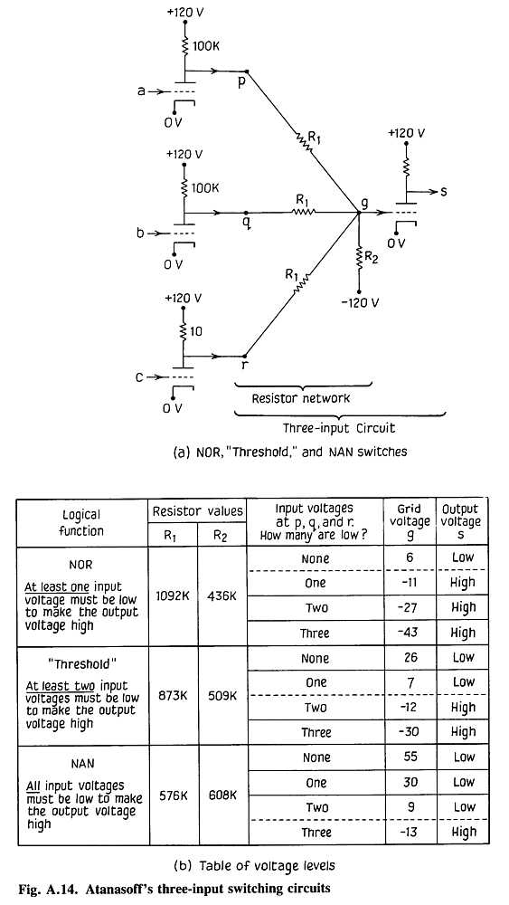
Fig. A.14
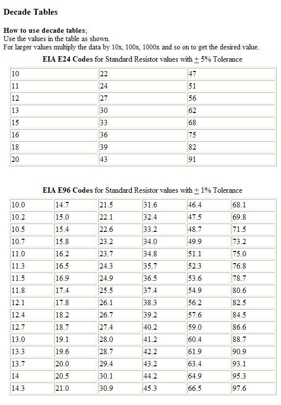
To make life easier, Electronic Industries Association (EIA) has set up standard
values, sometimes referred to as the "preferred value" system,
to be preferentially selected by designers and
usually available from manufacturers. - from www.interfacebus.com/resistor_table.html
Maybe I worry too much - others don't -
The vacuum tube selected by Atanasoff and Berry for the logic in the ABC computer was the 6C8G.
The tube was a medium gain twin-triode with independent cathodes.
According to
"Popular Science" Oct 1938 this was a new design in 1938.
It is listed in the
1937 Ratheon Receiving tube manual.
The 1968 RCA Tube Manual barely mentions the 6C8G tube, the functionality
long ago replaced by "miniature" 9 pin tubes such as the 6AU7.
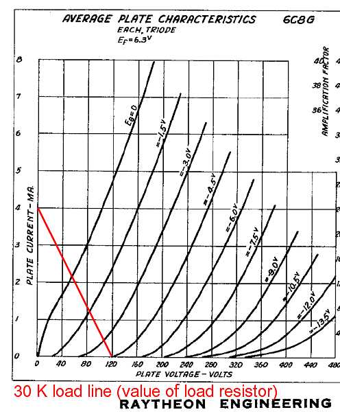
Engineers and technicians enjoy extracting more information by drawing "load lines" due to
the output impedance (resistance) in the plate circuit. One of the load lines shows what
happens to the output voltage of the tube relative to the grid voltage when the 50,000 ohm
load resistor (only) is in the circuit.
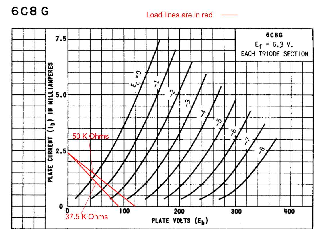
The other load line, marked 37.5 K ohm shows when
the plate circuit is loaded by two 300 K ohm resistors to the grids of two other tubes.
(The grids of the other tubes are expected to be near 0 volts.)
You might notice that Atanasoff and Berry designed very conservatively - they did not stress the tubes
with high voltages, currents, or heat. The tubes could be expected to have a much longer
service life than most.
Lets assume the "scanning brushes" make contact with the "switch points" 15 percent of a
bit time (bit time being 1/60th of a second)
and that the three inputs are in proper alignment. That is 2.5 milliseconds.
(The input capacitors ought to hold the input charge. Very high parallel resistance -
assuming they are clean and no fingerprints - and grid current in nano amps.)
Memory capacitors
(Replica)
The memory capacitors (in the memory drums) were
0.0015 microfarad
One might ask if those (then cute, now ugly oversize) 6C8G tubes had the drive current
to charge those 0.0015 microfarad quickly enough. A person
must ask "what is quickly enough?".
.
1.
When the tube is not conducting, the charge circuit is the capacitor and the plate resistor
( 30 K Ohms as in Figure 11 of Burks).
2.
When the tube is conducting heavily, the discharge of the capacitor through the
highly conducting 6C8G in parallel with the same plate resistor
1.
Atanasoff used the pentodes for superior capacitor discharging characteristics. (A pentode can
act more like a current source than a triode - which acts more like a variable resistor.)
2.
Berry decided that the 6C8 was good enough for this service and used it,
thereby reducing the numbers and types of tubes used.
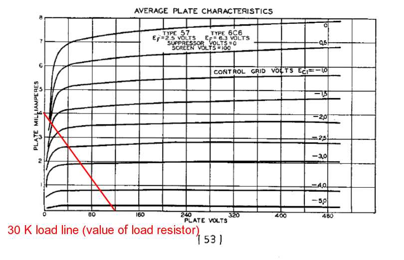
How to calculate the discharged memory capacitor voltage after several time constants, (see above)
The intersection of the red "30 K load line" with the zero grid voltage is the steady state
discharge voltage on the memory capacitor. This voltage is 15 volts for the 6C6 (pentode, left)
and 55 volts for one section of the 6C8 (triode, right).
 6C6
6C6
 6C8
6C8
Or listening to many politicians we elect, getting paid much less, defy logic and the sense
baby geese have at birth?