|
The paper version of this document was obtained from Doron Swade then of the British National Museum of Science & Industry on August 6, 1999 and is published here with his permission. Please recognize that scanning and OCRing and conversion to HTML is an imperfect art, and differences from the original must be considered to be present. Notes to viewers
Converter's comments
A serious viewer's comments here. |
|
Charles Babbage's Difference Engine No. 2
Technical Description |
|
Science Museum Papers in the History of Technology
No 5 Doron Swade September 1996 |
| Preface | 1 |
| Forward | 3 |
| Printing | 7 |
| Stereotype Table | 37 |
| Calculation | 65 |
| Circular Motions | 83 |
| Vertical Motions | 89 |
| Drive | 113 |
| Framing | 123 |
| Build | 131 |
| Appendix: Drawings | 147 |
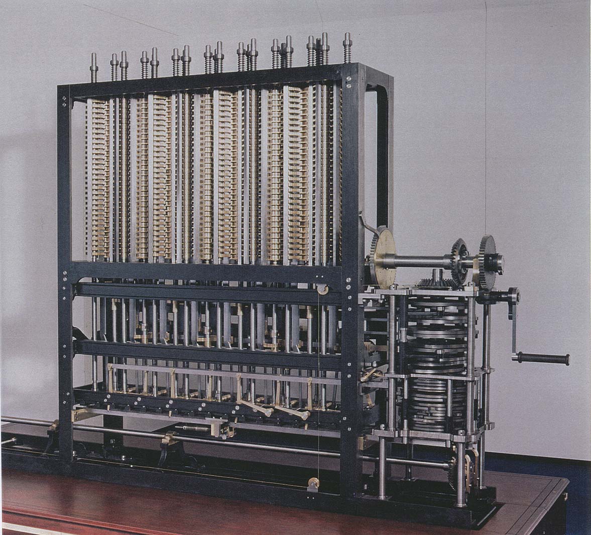
Photo of Babbage Difference Engine No 2 (214 K bytes)
The documentation project started in January 1993. The account is the product of a series of
debriefing sessions between the author and Reg Crick, the engineer who played the
major part in the production of the new drawings and in the construction of the engine. The
documentation process is described in the Foreword to the Work in Progress' report
(included below) issued in February last year.
This first draft is issued to mark the completion of the debriefing phase of the documentation
process. Since the work will now be intermitted it is also issued as a form of security in the
event that the work is not resumed. The contents of the Work in Progress report (February
1995) remains unchanged. However, two sections have been added to the account during
the last year. The overall account runs to 58,000 words. These sections complete the
description of the stereotype table and add a final section covering issues that arose during
the physical assembly.
The account is intended as an interpretative companion to the set of twenty original
full-sized design drawings and twelve tracings for Difference Engine No. 2, produced by
Babbage, or under his instruction, between 1847 and 1849. Babbage made liberal use of
his Mechanical Notation in the depletion of the engine in these drawings. The Notation
is an elaborate system of symbols devised by Babbage to identify parts and describe their
operation. It consists of alphabetic characters of various kinds which identify fixed and moving
parts, and numerical superscripts and subscripts which indicate the operational relationship
between parts. The original drawings are large (typically 1000 x 600 mm)
and well able to convey the fine detail of the Notational annotations. Reduced copies of
the twenty main drawings are provided here in an Appendix. Most, though not all of the
alphabetic annotations are legible in these copies but the notational super- and sub-scripts
have inevitably suffered in the reduction. The textual account relies on the Notation to
identify parts but in general does not rely on it for the description of the operation of
mechanisms. Despite the diminished detail of the reduced copies the account that follows
does provide a freestanding description of the engine without reference to the full-sized
original. However, for detailed study of the Notation and its use in Babbage's description of
the engine three is no substitute for reference to the full-sized primary sources.
Some progress was made on the Mechanical Notation during the last year and this helped to
resolve a major issue in the design of the stereotype table. However, current understanding
of the Notation is still in complete and its study is a research task that remains outstanding.
Doron Swade
Work in Progress (February 1995)
This account documents the construction of Difference Engine No. 2 taking the original set of
Babbage's drawings as an uninterpreted datum. The purpose of the account is to place on
record the detailed interpretation of a Babbage engine design, it also serves to provide a technical
record of the process by which a project, arrested in 1849, was resumed and
culminated in the completion, in 1991, of an operational machine.
The accompanying account describes Charles Babbage's Difference Engine No. 2. The
machine was built by the Science Museum to original designs dating from between 1847
and 1849. The engine was completed in 1991, the bicentennial year of Babbage's birth.
The set of original design drawings consists of twenty main views and a small number of
derivative tracings. The set is believed to be complete i.e. there is no evidence of drawings
being missing. The drawings collectively constitute a comprehensive operational description of
the engine: they are sufficiently detailed to describe the shape and nominal size of individual
parts, their physical interrelationship and their intended function. However, for all the richness
they contain the drawings are not 'working drawings' i.e. they are not sufficiently detailed to
provide the full specification necessary for the manufacture of parts. No information is
provided in the originals as to choice of materials, methods of manufacture, requisite
precision, or finish. In this respect they provide a schematic description, comprehensive in
itself, but insufficiently detailed to serve directly as a specification for manufacture.
The drawings are deficient in other respects: they contain dimensioning inconsistencies
(the same parts are shown differently sized in different views); there are incompletenesses in
the design, instances of omitted devices, as well as redundant assemblies. The drawings also
contain design errors one of which is central to the fundamental operation of the engine.
None of these deficiencies compromises the validity of the basic logic, design or intended
function of the engine. Babbage made no practical attempt to construct the engine and the
deficiencies for the most part represent the gap between an advanced design arrested in an
incomplete stage of engineering development, and the final working mechanical entity. The
gap, in short, is one of engineering completeness rather than logical or operational principle.
The drawings constitute the only original account of the engine. Babbage provides almost no
other explanation, textual description or justification for the design. The drawings are
therefore a free-standing source from which his intentions are to be decoded and
reconstructed.
The manufacture of parts required fully specified working drawings. These include detailed
piece-part drawings, parts lists specifying quantities of individual components, layouts and
general assembly drawings detailing the physical interrelation of assembled parts. The
production of these drawings required detailed interpretation of the originals to establish the
purpose and function of parts and subassemblies. This interpretation then informed the
provision of supplementary data, otherwise missing from the originals, but essential for
manufacture. Composition analysis of contemporary gunmetal informed the choice and grade
of modem bronze; which parts where to be made from bronze, cast iron or steel, methods
of manufacture, finish and tolerancing were informed by expert curatorial advice based on
detailed knowledge of nineteenth-century practice. The guiding principle throughout was
authenticity, and care was taken to ensure that no part was made with greater precision than
is known from measurement to have been deliverable in Babbage's time. Dimensioning
inconsistencies were resolved, incompletenesses in the design remedied, modifications to
correct design errors specified and omissions and redundancies catered for. These researches
and deliberations were embodied in a set of some fifty working drawings which completely
specify the engine. During the design and build Reg Crick, the senior engineer responsible for
the production of the modem drawings and for the supervision
of the construction, kept an Engineer's Log (The Red Book) which is an episodic diary of
notable issues. Apart from this we were as guilty as Babbage during the design and build
phases of the project in providing little descriptive account of the technical issues
underpinning the design. The attached account is intended to remedy this, at least in part.
The documentation process started in January 1993 and has continued fairly consistently since
then. The account is based on debriefing sessions between myself and Reg Crick. During the
debriefing sessions the interpretation of the original drawings is retraced and reexamined so
as to reconstruct the supposed intention and function of the various devices. Deficiencies,
where they occur, are identified, and the means and justification by which they were resolved
described. The Engineer's Log (The Red Book) is used as a checklist of notable issues. My
role in these sessions progresses from disciple, to inquisitor, and finally, to that of scribe. The
debriefing sessions are recorded in handwritten summary session notes by me. These are
then taken away and used in solitude as the basis of an expanded account written usually on
the same day or in the days immediately following. In the next session Reg Crick would
proof read the text Secondary questions raised during the drafting process, as well as
amendments to the text from the proofing process would be discussed, clarified and resolved.
The account would then be redrafted accordingly and re-read at the start of the following
session. The pages attached are the outcome of the process to date.
There are two flagged incompletenesses in the account. These are provisional omissions
which require curatorial research outside Reg Crick's or my immediate knowledge. One
of the topics is the use of Babbage's Mechanical Notation. Despite the central importance
attached by Babbage to the Notation as an interpretative and descriptive tool, we did not use
it to decode the drawings nor in the construal of Babbage's intentions. While I have used the
Notation in the later sections as a short-hand to identify parts, this is the main use to which it
has so far been put in the written record. The account will need to be reviewed in the light
of a more informed understanding of the Notation to verify and confirm interpretative
decisions taken without its aid. An investigation of the notational conventions devised by
Babbage is a necessary curatorial research task but is being held in abeyance until the technical
account, which relies on Reg Crick's unique experience and knowledge, is complete. The
second issue is the historical account of a major design error in the addition mechanism. This
requires reconstructing the sequence of interpretative exchanges between Prof. Allan Bromley
and the engine team. Retracing the trajectory of understanding here is not essential to the
debriefing process. This too has been postponed for the meanwhile but will need to be
returned to for completeness.
The engine depicted in the original design drawings consists of a calculating section to which is
attached a printing and stereotyping apparatus. Only the calculating section has so far been
built. The description of the calculating section is retrospective i.e. this part of the engine
existed as a fait accomplis at the time of writing. The account is therefore 'descriptive' in the
literal sense (de - down, scribo - I write) and my role here is largely that of a scribe
retracing, recovering, articulating and recording, via a process of understanding, a set of
considerations and events already enacted. The account, however, also covers the printing
and stereotyping section which remains unbuilt but for which working drawings were
produced in the interval since the bicentennial year, funded by independent sponsorship from
the United States. The relationship between the process of documentation and the process
of design is in this case different.
The printing and stereotyping section is integral to the concept of the machine and forms an
essential part of the engine's control system. The apparatus is at least as complex as the
calculating section, and calls for an additional 4,000 parts - about the same number as
required for the calculating section already built - but with substantially less repetition of
similar parts. Documenting the printing and stereotyping apparatus involved the familiar
process of re-examining the existing interpretation of the original design intention, and
retracing the decisions made in designing the incompletely designed parts of the mechanism.
The opportunity for curatorial scrutiny was greater here than circumstances allowed during
the earlier build of the calculating section, and since there still existed the possibility to
re-interpret the design, the curatorial responsibility was correspondingly greater. The process
of reviewing the design substantially altered our understanding of the printing mechanism and
revealed features of startling subtlety formerly overlooked. The design
was subsequently altered to accommodate this partial re-interpretation. I cite this to illustrate
how, in the case of the printing apparatus, the documentation process and the design process
directly interacted and breached what had until then been separate activities.
The account consists of seven sections which collectively run to 45,460 words. A total of
300 hours has been spent on debriefing and writing up since January 1993 (192 hours in
1993, 96 hours in 1994, and 12 hours in 1995). The ratio between debriefing time and
write-up is about 1:2 i.e. each hour of debriefing requires a further two hours of formulation,
research and writing. The technical account based on one-to-one debriefing sessions is within
an estimated 6,000 words of completion (2,000 words outstanding for the stereotype
apparatus and 4,000 words for the final section which will describes the assembly of the
engine). The writing rate is typically 180-200 words per hour.
The order in which the sections are presented is in the reverse order of writing i.e. the earlier
sections are last, the most recent first The genre of writing is highly intemalist and allows
little linguistic licence. The earlier sections (appearing last) tend to be costive, taut and formal.
As the genre developed the style, though inevitably still constrained, tends nonetheless to be
slightly more expansive.
Doron Swade
Go to next section Printing
Appendix: Drawings - permission to post from Doron Swade
Preface
15 March 1996
9 September 1996
Foreword
25 February 1995
Go to top of Babbage Technical Description
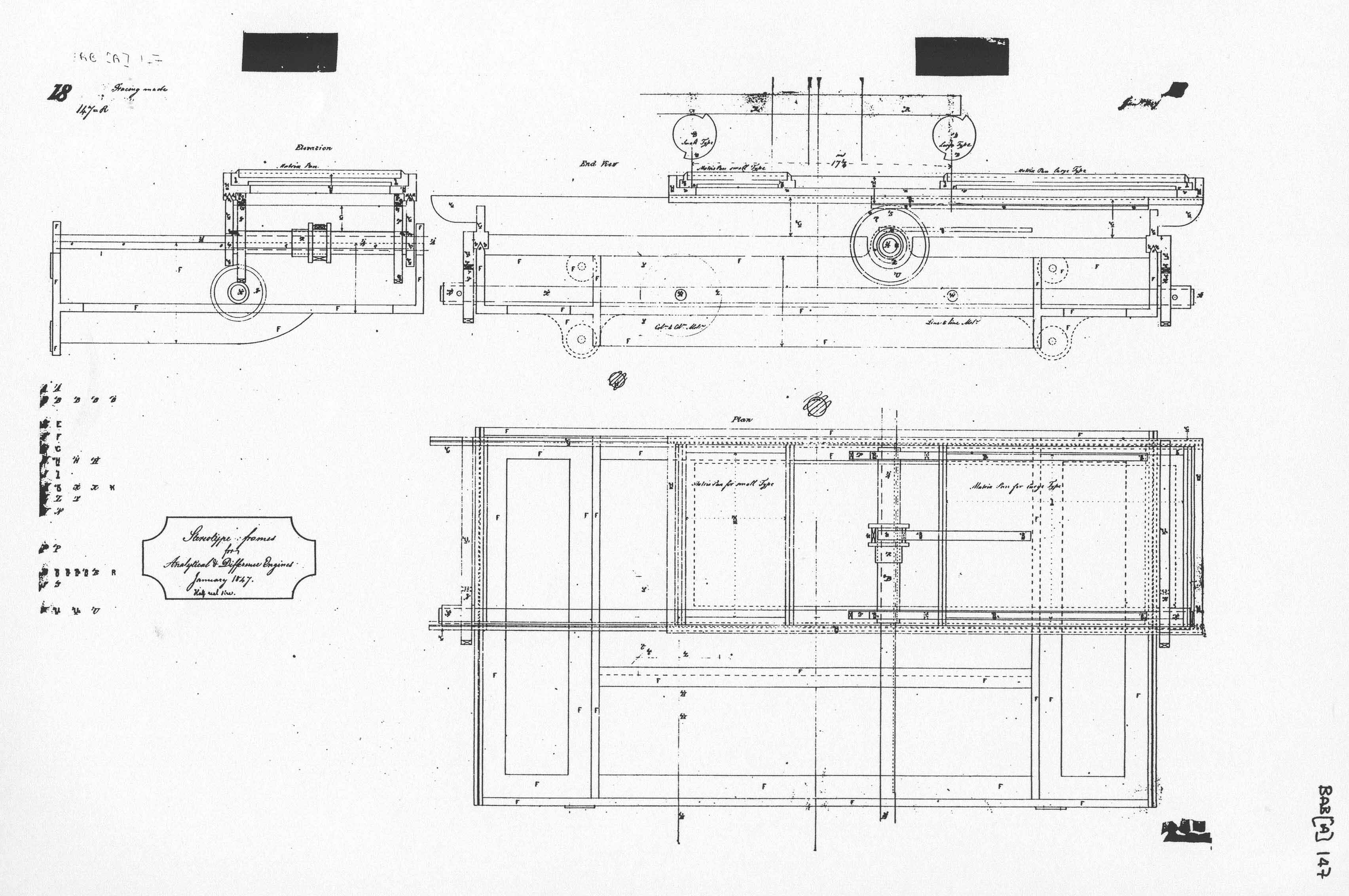 Drawing 147 Stereotype frames for Analytical and Difference Engines 473 K bytes |
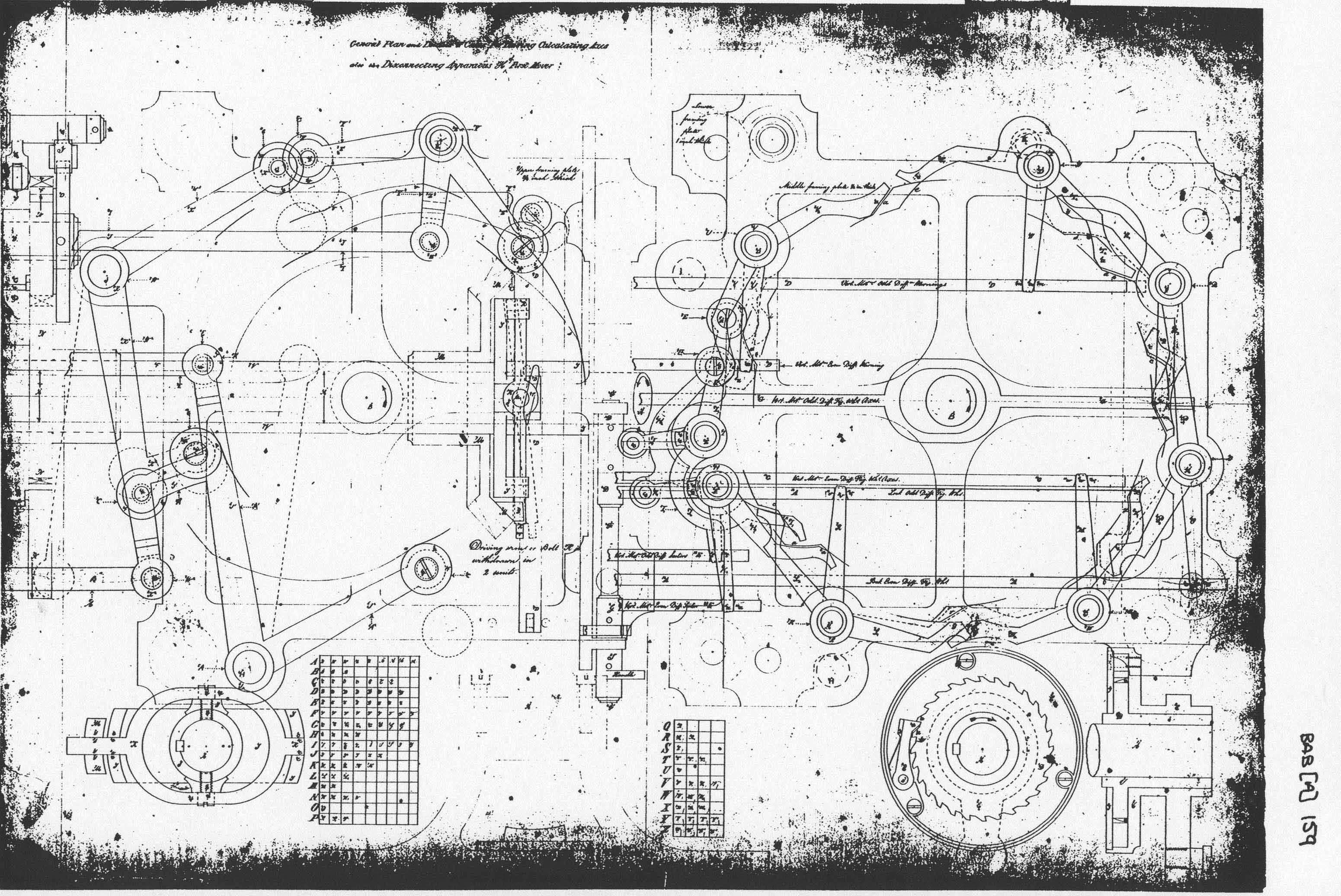 Drawing 159 General Plan and Details of Cams for Driving Calculating Axes 783 K bytes |
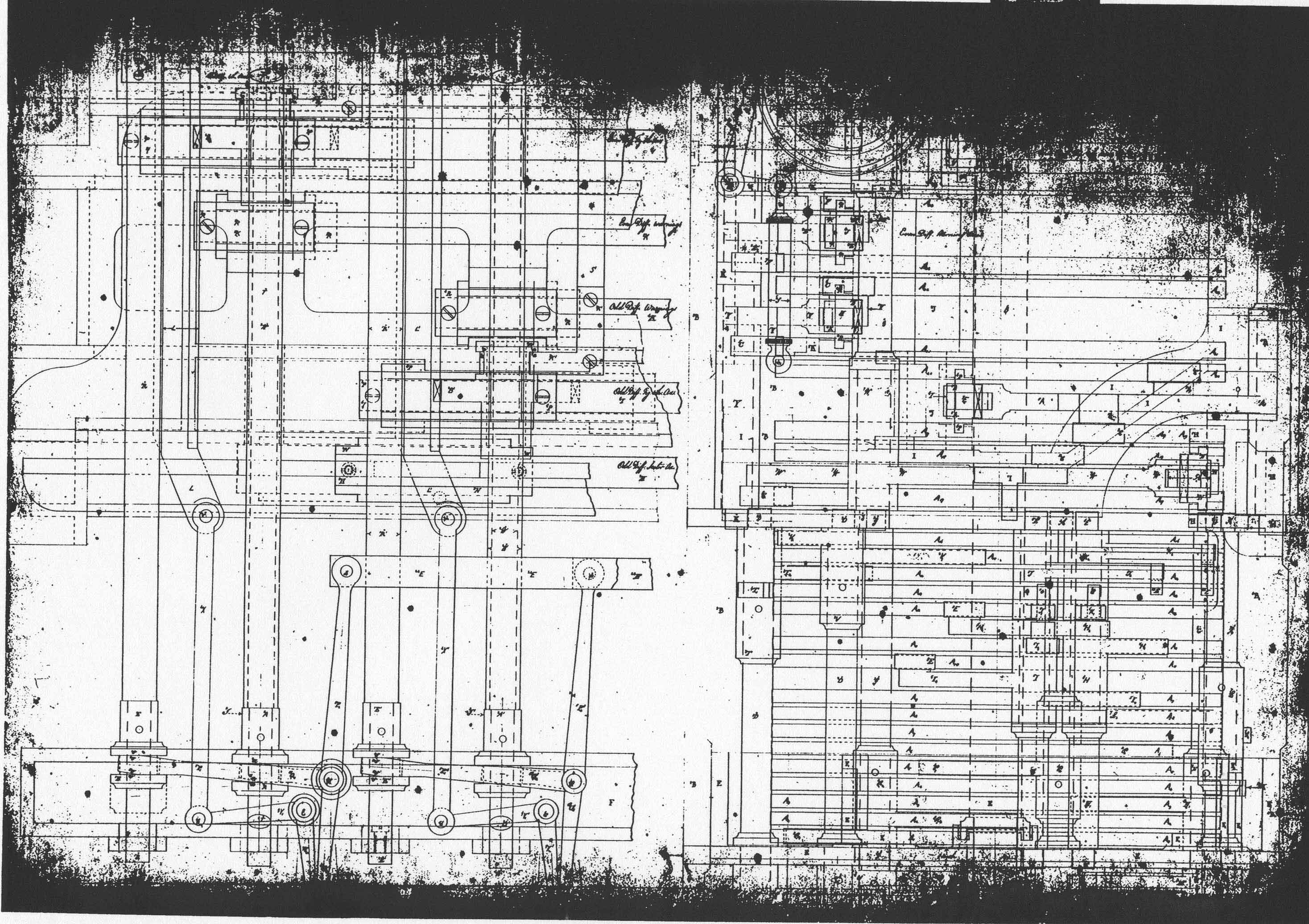 Drawing 160 [Untitled] 810 K bytes |
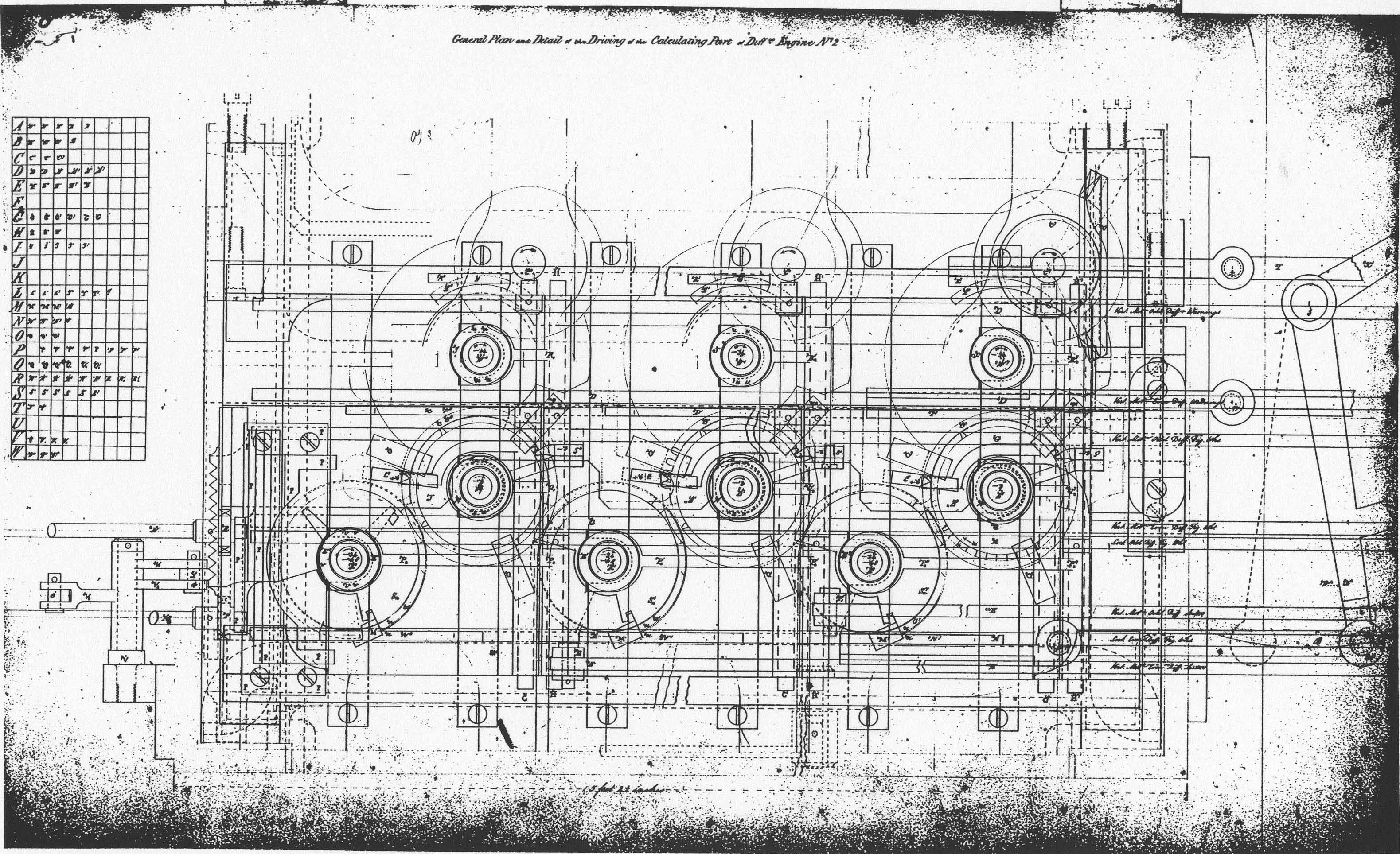 Drawing 161 General Plan and Detail of the Driving of the Calculating part of Difference Engine No. 2 891 K bytes
| 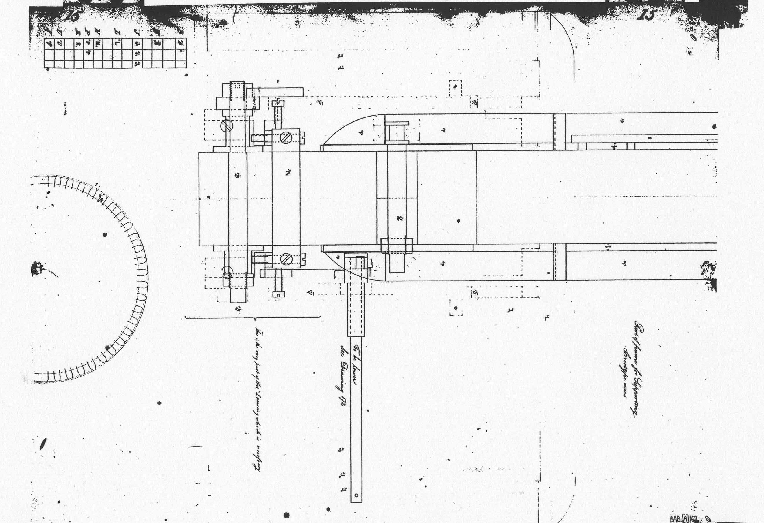 Drawing 162 Part of Frame for Supporting Stereotype axes 279 K bytes
| 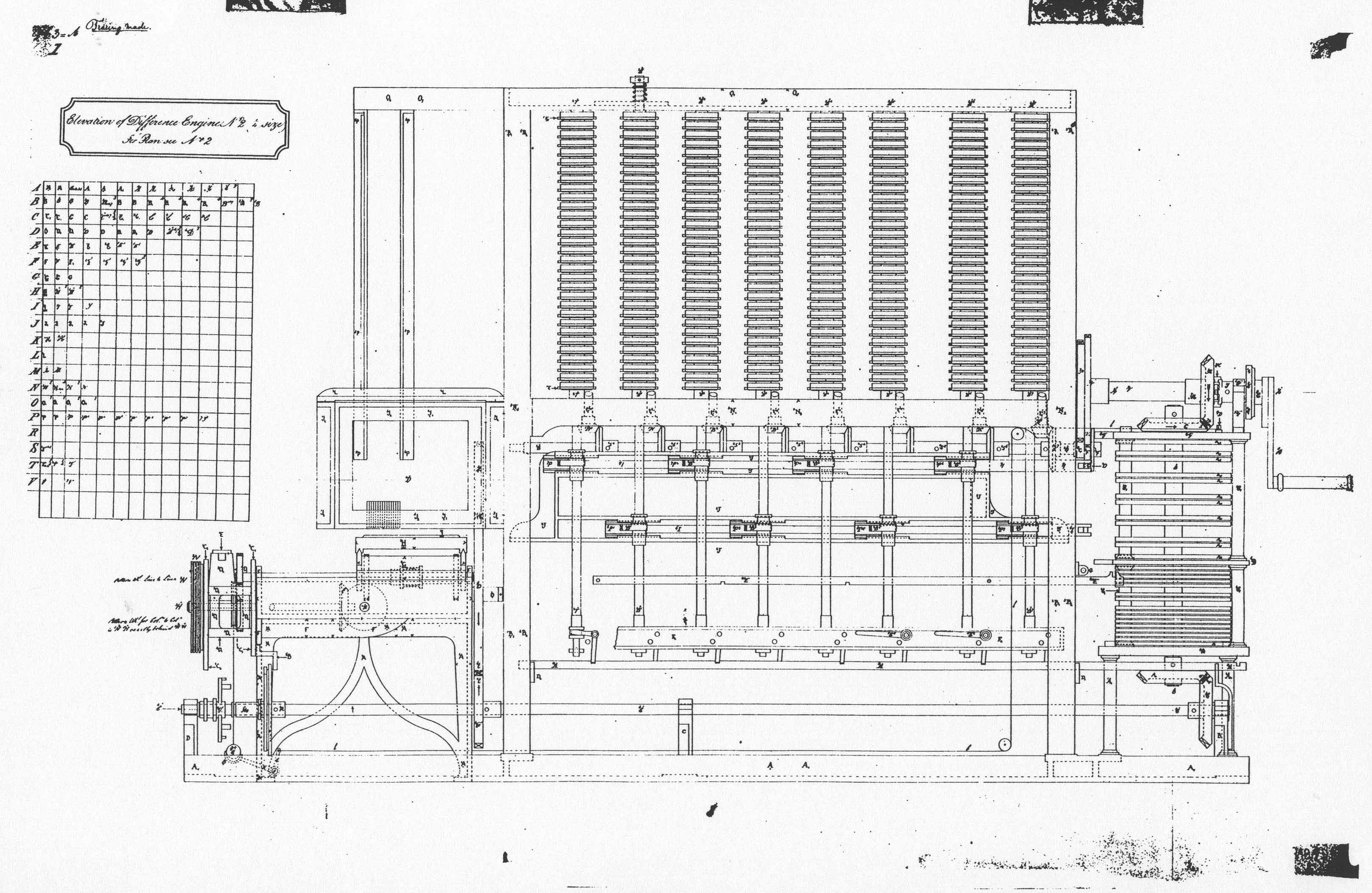 Drawing 163 Elevation for Difference Engine No. 2 596 K bytes
|  Drawing 164 Plan of Difference Engine No. 2 343 K bytes
|  Drawing 165 - End View and Elevation of Paper Rollers - End View and Plan of Carrying Axis and Driver - End View and Elevation of Supports 675 K bytes
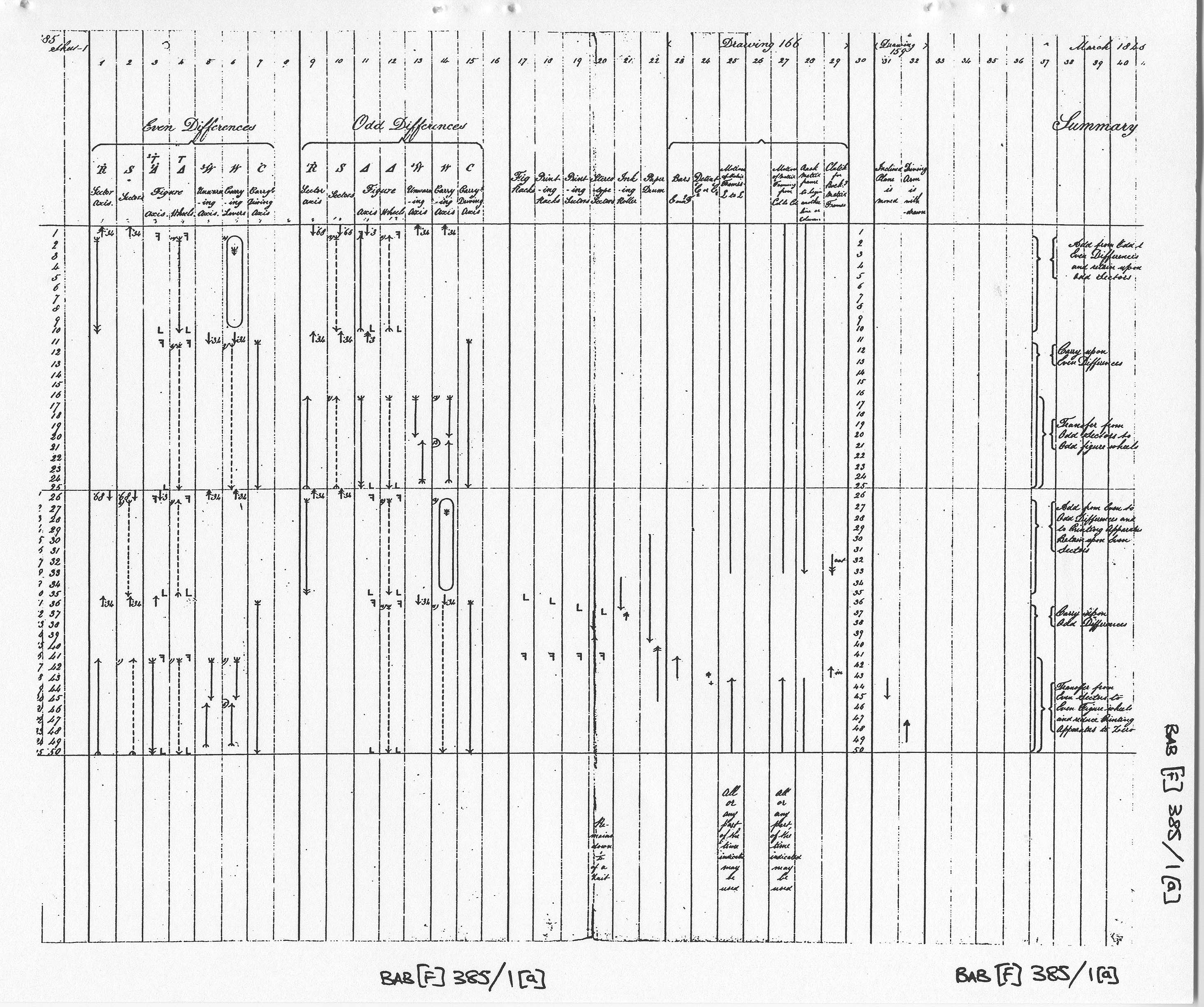
|  Drawing 166 Apparatus for moving Stereotype frames for Analytical and Difference Engines 611 K bytes
| 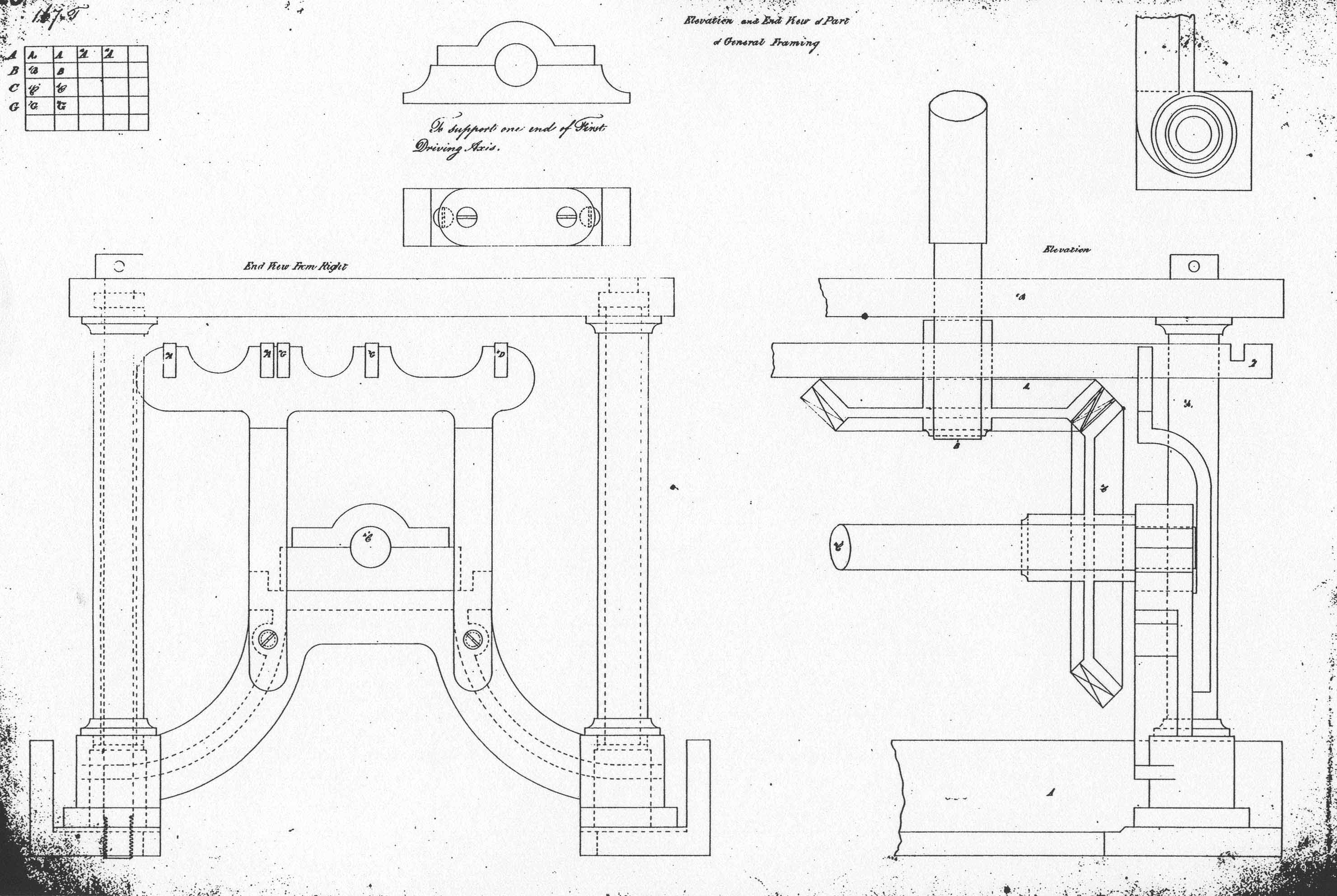 Drawing 167 Elevation and End View of Part of General Framing 393 K bytes
| 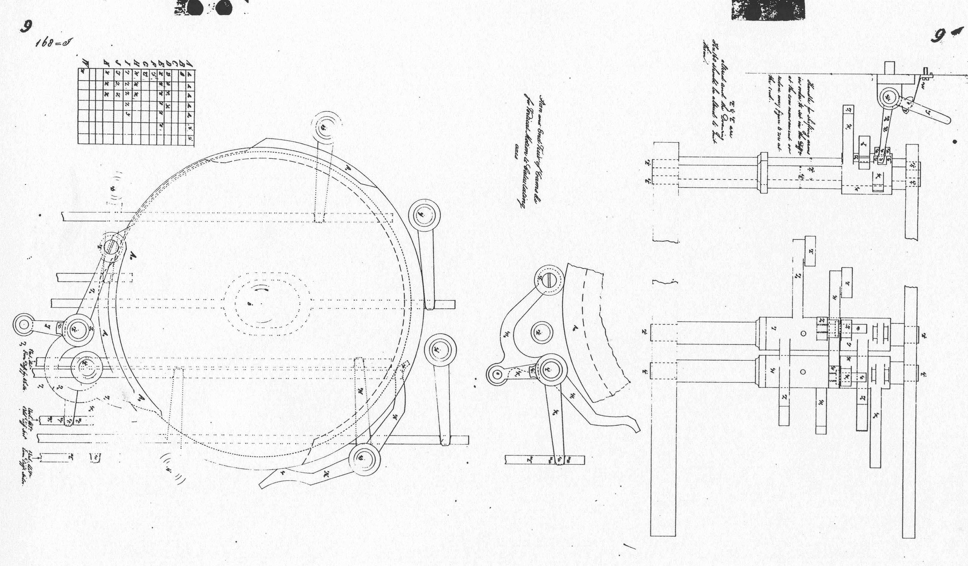 Drawing 168 Plan and End View of Cams etc. for Vertical Motion to Calculating axes 399 K bytes
| 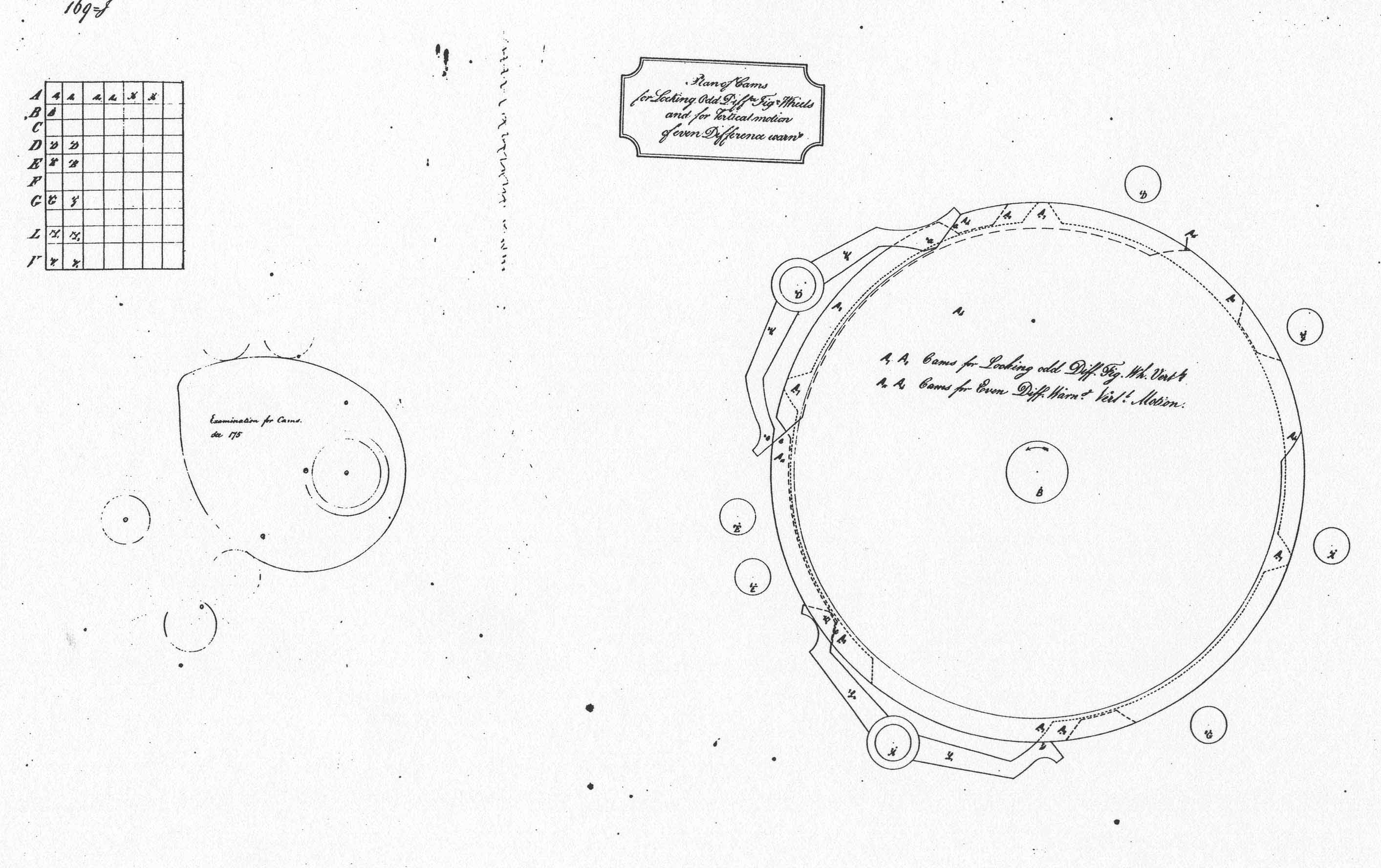 Drawing 169 Plan of Cams for Locking Odd Difference Figure Wheels and for Vertical motion of Even Difference warning 309 K bytes
| 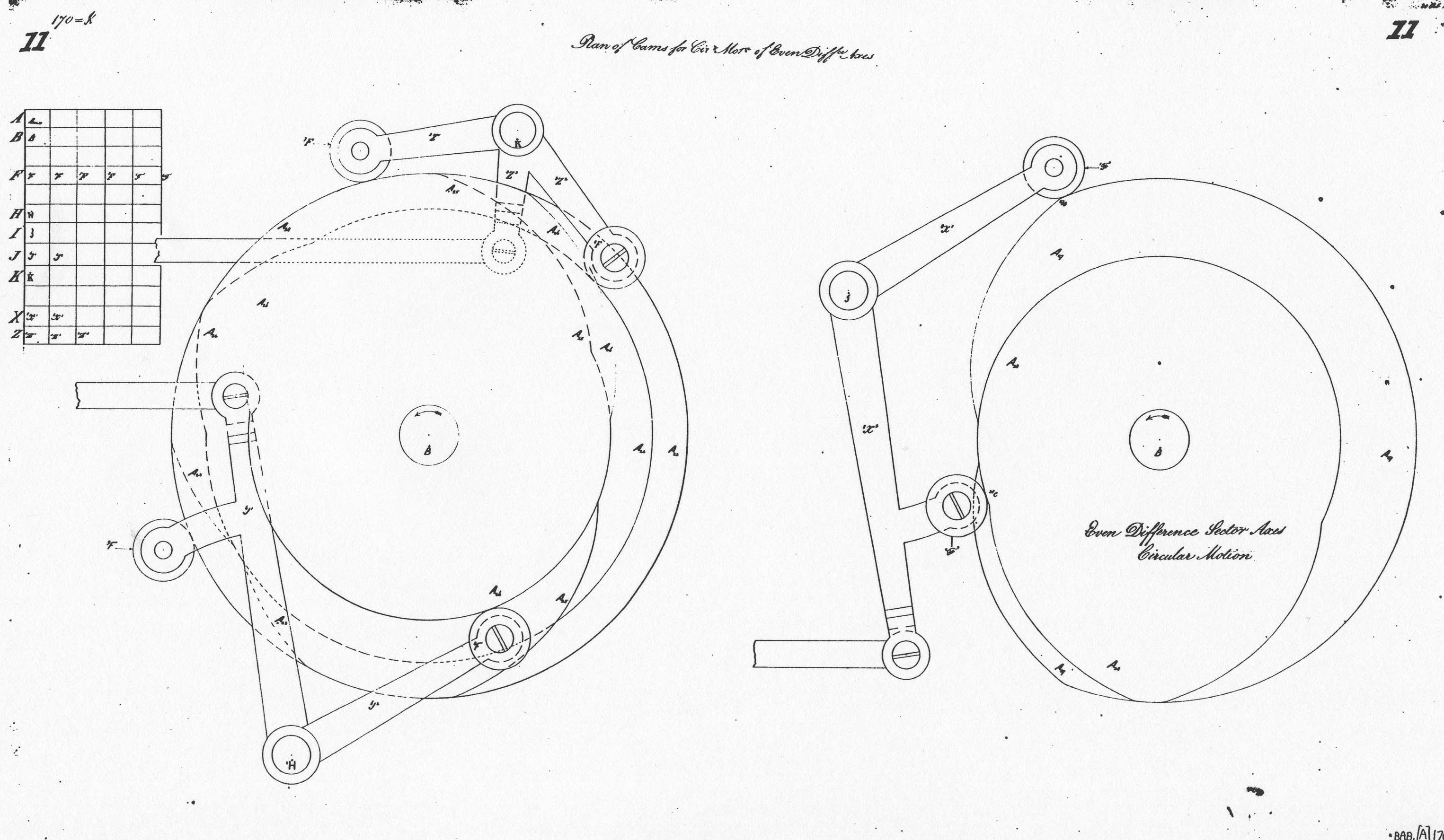 Drawing 170 Plan of Cams for Circular Motion of Even Difference Axes 355 K bytes
| 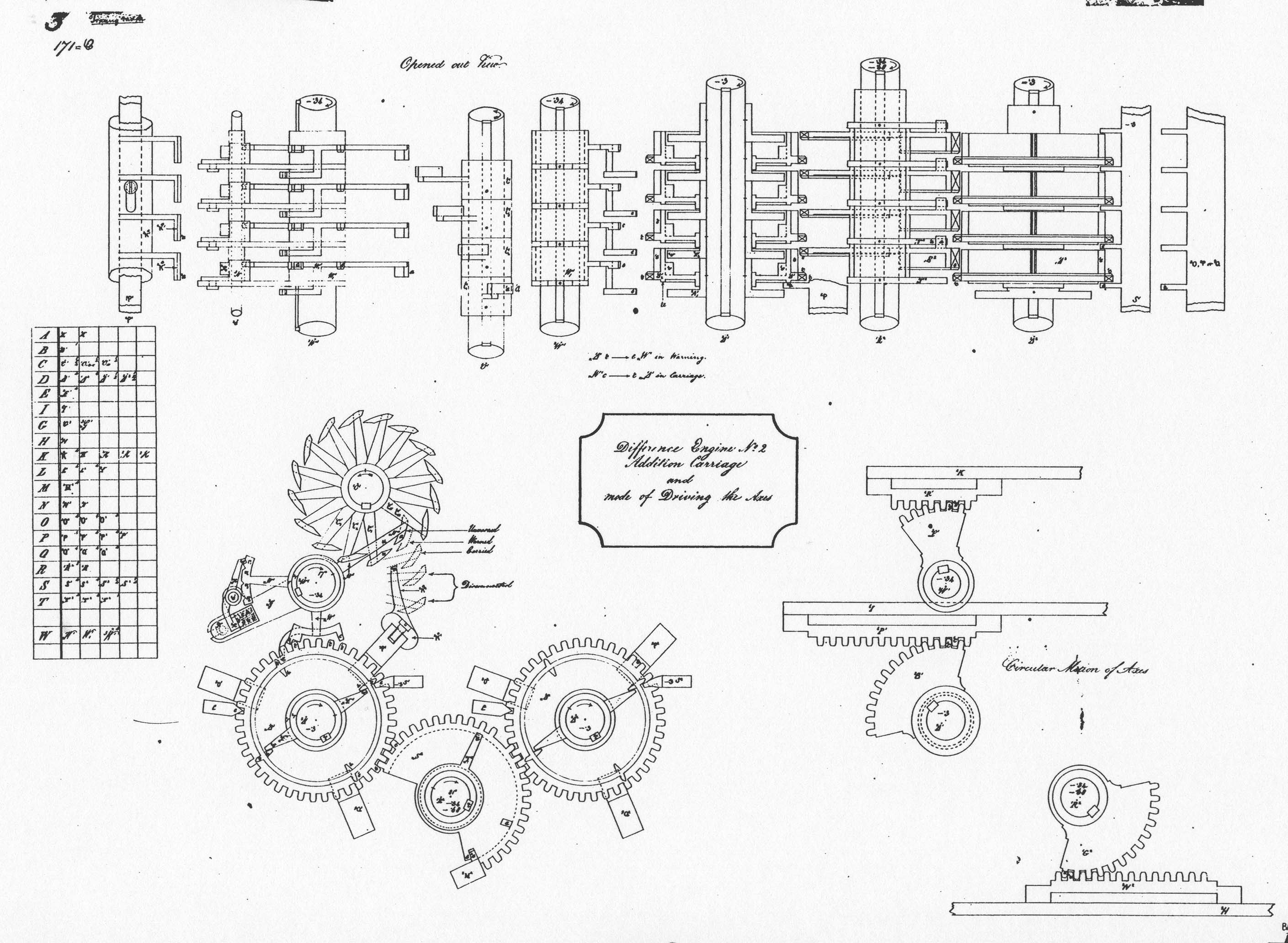 Drawing 171 Difference Engine No. 2 Addition of Carriage and mode of Driving the Axes 546 K bytes
| 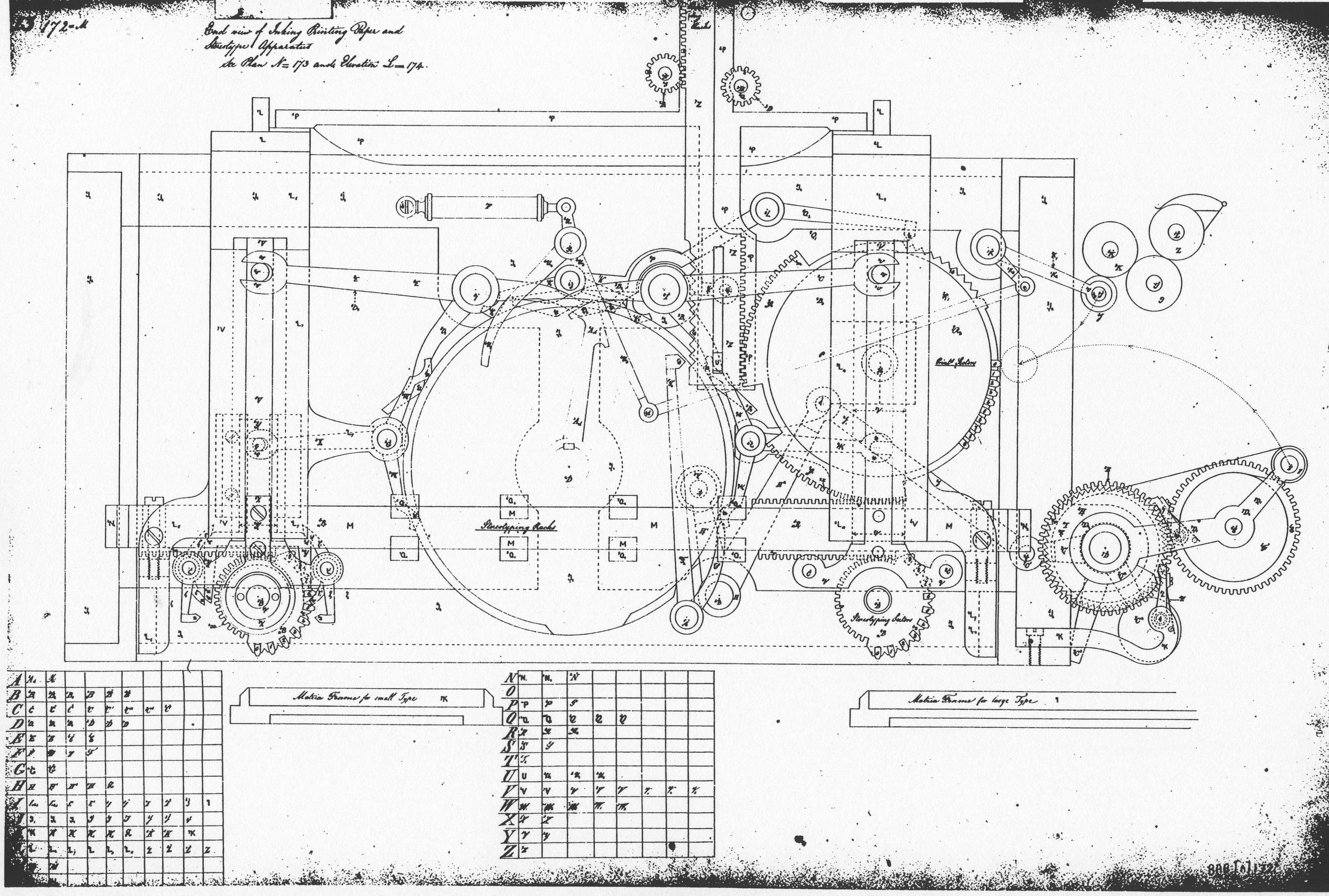 Drawing 172 End View of Inking Printing Paper and Stereotype Apparatus 786 K bytes
| 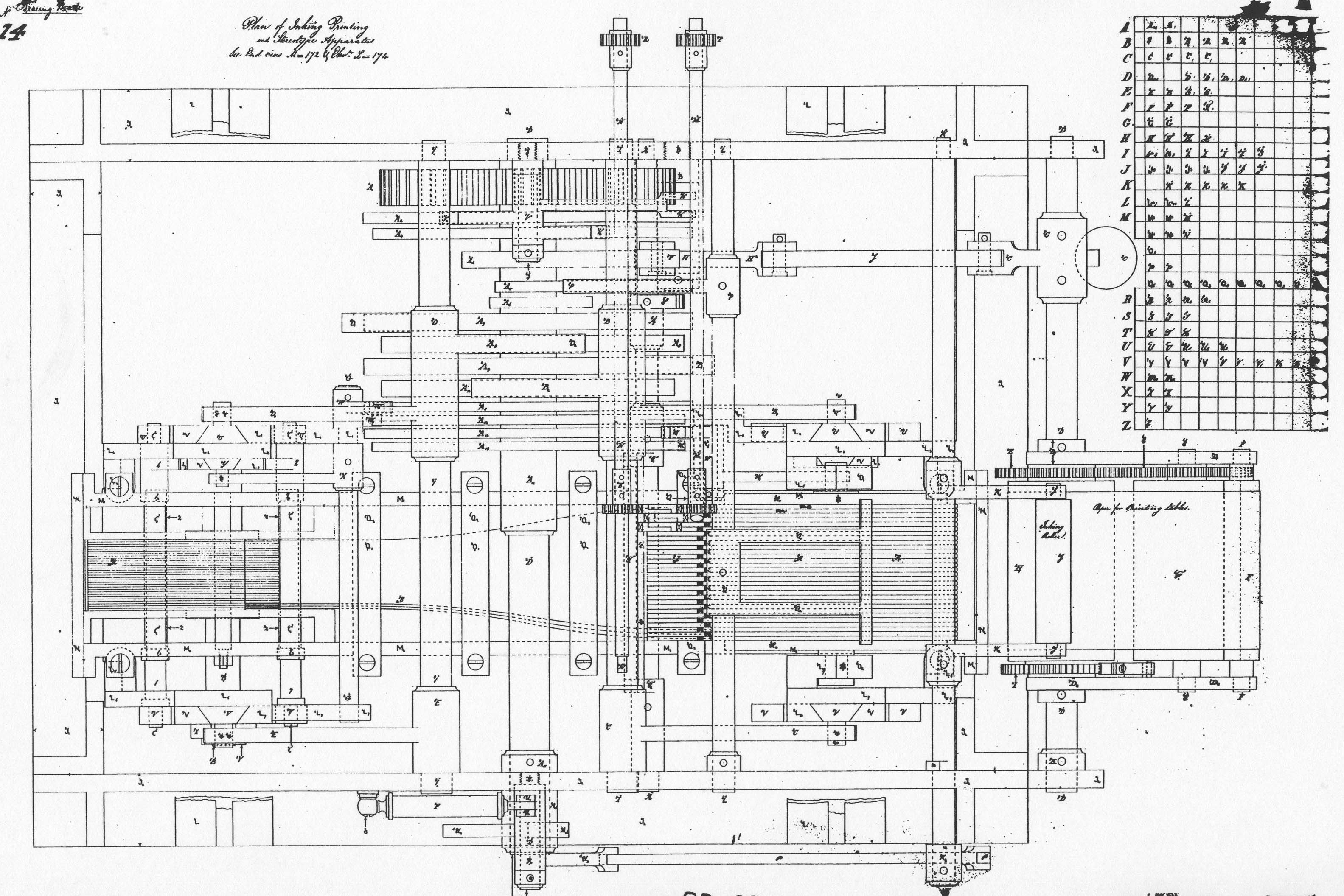 Drawing 173 Plan of Inking Printing and Stereotype Apparatus 790 K bytes
|  Drawing 174 Rack Pinions for connecting Table figure wheels with Printing Stereotype Sectors 802 K bytes
|  Drawing 175 Plan of Cams for Punching with small stereotype sectors, and Cams for removing Paper Rollers 384 K bytes
| 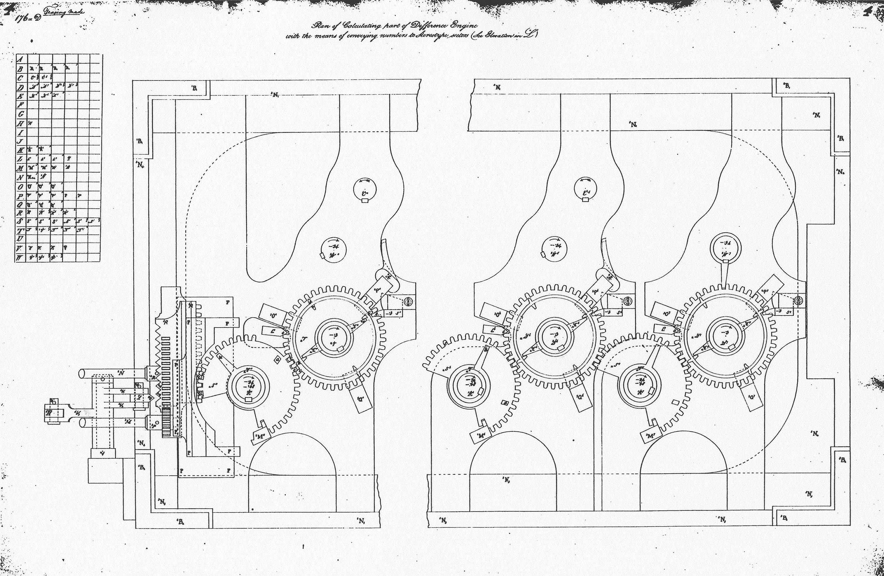 Drawing 176 Plan of Calculating part of Difference Engine with the means of conveying numbers to Stereotype sectors 785 K bytes
| 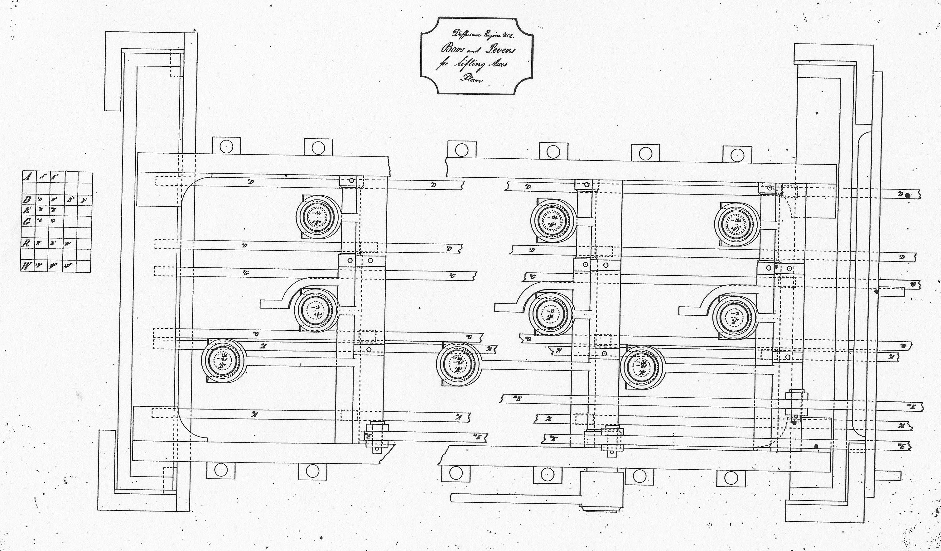 Drawing 177 Difference Engine No. 2. Bars and Levers for lifting Axes 665 K bytes
|  Drawing 337 Addition Carriage (Modified) 896 K bytes
|  Drawing 385 Notation of Units for Difference Engine No. 2 985 K bytes
| 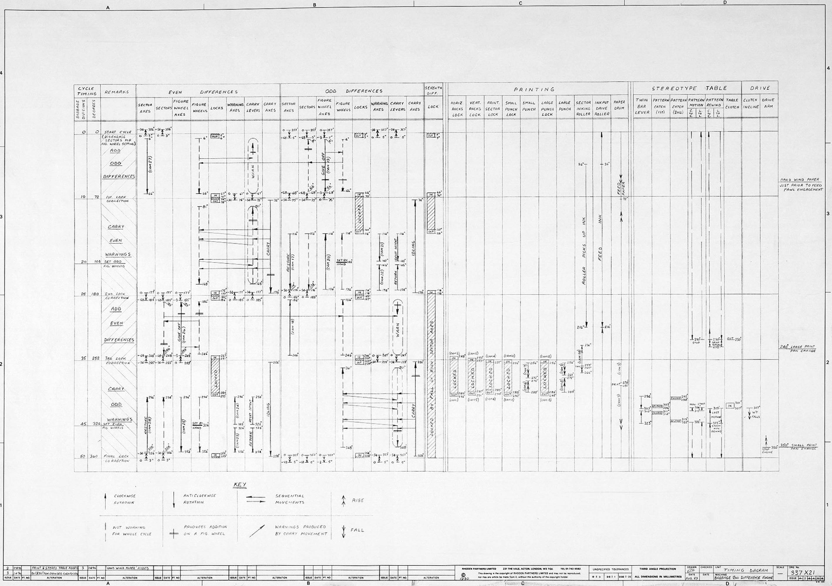 Modern Timing Current timing diagram Difference Engine No. 2 675 K bytes (not in technical manual) |
A serious viewer's comments here.
I was reading the comments at the end of "Charles Babbage's Difference Engine No. 2 Technical Description" by Mr. Swade. The answer to why Mr Swade description appears to be in error is that both Alain Calzas and Jan-willem De Bleser assume all the columns are digit wheels are numbered in the same manner (all increasing as they rotate clockwise). This is not true and can be seen in many of the videos available on youtube. The numbering alternates from increasing in the clockwise direction to increasing counterclockwise direction for each column from left to right. This is clearly shown in Tim Robinson's video of his meccano version named "part 2 front close up". So Mr Swade's description is exact. Marc LaViolette Assistant Professor Dept. Mechanical and Aeronautical Engineering Royal Military College of Canada Kingston, Ontario, Canada |
from Tim Robinson < tbr00 (at) pacbell . net > March 8, 2006
from Jan-willem De Bleser < jan-willem . debleser @student .kuleuven .be > March 7, 2006
Jan-willem De Bleser wrote:
> That would most certainly be another valid way to design it. To know
> which  was Babbage's design you'd have to study his timing diagram -
> something I  haven't found the time for yet.
>
   His timing diagram (which has some errors) definitely assumes the
   alternating columns.  The reason is that with alternating columns you
   can overlap the restoring of the source wheels with the carry operation
   on the result wheels.  If instead you made all the columns in the same
   order then you would have to transfer the value to the sector from the
   source, restore source and add, and then finally carry, so all these
   three would have to be sequential and it would slow the cycle down.

   Since Babbage was quite obsessed with speed, it seems very unlikely he
   would have done this just to avoid mirroring the columns.  However the
   timing diagram and the details of the cam profiles make it clear he
   intended to use the alternating column approach.

> You say this reversed setup is how the actual machine in the Science
> Museum is built? Have never seen it myself, sadly enough.
>
   Yes, they did make this change.  In my own model I followed the same
   path, however I did find some further optimizations which reduced the
   number of independent controls from what Babbage used.  I don't know if
   he simply overlooked these.  More likely he chose not to exploit them,
   preferring to keep the flexibility of fully "horizontal" control.  He
   may also have been concerned about uneven wear from the greater load
   which some control paths would have to take with the optimizations in place.

   Tim Robinson
I am no expert on the difference engine but I believe that what Alain
states is correct - his explanation is in fact one way it would work as
drawn.

Consider Doron's  description of the "Giving Off" phase:

1) The sector wheel is fully engaged and the right hand drive axis is
lowered.
2) The right axis is rotated 81 degrees clockwise, reducing the count to
zero and driving the left wheel via the sector wheel.
3) The right wheel is now zero and the left wheel is the sum of the
original value and the right value.

There is one inconsistency in this explanation: both figure wheels are
rotating in the same direction and thus must both be decremented or
incremented, assuming the same direction of numbering. This means that it
is impossible for the right wheel to be reduced to zero while
simultaneously increasing the value of the left wheel. Alain's solution
solves this, as first the right figure wheel is reduced in value, followed
by both figure wheels being increased in value.

Jw