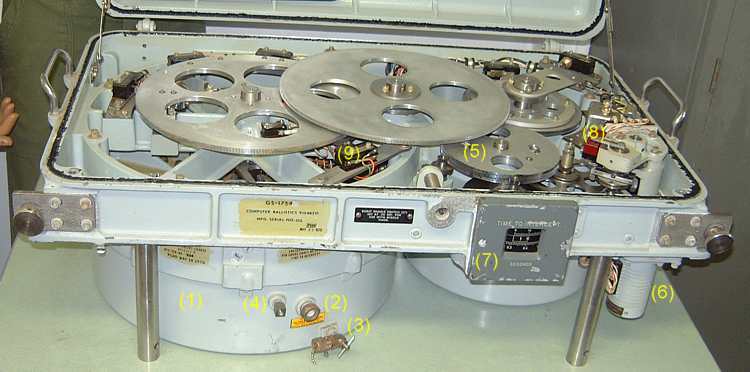
This is the Time Potentiometer drawer. All precision multiplying and dividing by time was done by this potentiometer. Computer test modes, computer test problems, radar offsets, and power supply status were also controlled or viewed here.*NOTE* - This "time" is estimated/computed "time to intercept". It is not "wall clock" time. The value of "time to intercept" could get smaller and larger - what ever was needed to make the problem "converge".
Visible are the knobs to hold the drawer into the cabinet, and the steel pull handles to help pull it out. Also at the top of the picture is a partial view of the cover (to keep dust and fingers out).
Components in this Time Potentiometer drawer include:
- The can containing the seven windings of the time potentiometers. Site technicians such as myself were NOT authorized to dive into this can for a look. (Central Ordnance folks were authorized to open and repair potentiomenters - none of the computing potentiometers at our site failed. Very uncommon!! )
I have seen pictures of tapered (?bakelite?) strips wrapped into concentric circles - each strip wound with resistance wire. Also inside the can are brushes (connected to the central rotating axle) to slide along the resistance wire to make contact at the appropriate points. The sliding points are determined by the rotated position of the central axle.
To help with potential heating and lubricating problems, the can was mostly filled with a special oil.
- A sealed transparent port to assure that the correct level of oil was installed in the can. You should see the air/oil interface in the little window.
- The drain hole for the potentiometer oil. In theory we could have changed the oil - but there was no schedule to do that and we maintenance folks could see no reason to fix something that ain't broke.
- This is the fill hole/valve for the potentiometer oil. If the oil got low, we could have added some - it never got low.
- One of the gears in the gear train between the servo motor (6) and the time potentiometer axle.
- The servo motor - a two phase 400 hertz (cycles/second) motor driven by a vacuum tube power amplifier to drive the time pot. This motor
- The "time to intercept" visual read-out. In theory the computer operator was supposed to read off this value to the Battery Control Officer (BCO). In practice, the BCO could determine "time to intercept" as quickly and with less distraction by glancing at the right hand plotting board.
At our site the computer operator did nothing but watch for red warning lights indicating that the computer was not "settled" - correctly solving the problem - boring - no face.
- This is one of the "microswitches" along the gear drive train. This switch closed at 120 milliseconds before every second, and used with other switches along to gear train determined the 120 milliseconds before time zero - impact. This 120 milliseconds before time zero was used to send the burst command to the missile.
- This is another of the "microswitches" along the gear drive train. One of these was used to determine "10 seconds before time zero". At "10 seconds before time zero" full steering commands were sent to the missile. Before that time, steering commands were somewhat reduced to reduce the aerodynamic drag on the missile if there was rough (noisy) tracking of the target.
Go back to main tour