This 14 page SAGE document was handed to visitors of SAGE centers. The document is complete except for 6 photos at the end. Many thanks to Bill Shaw for providing a Xerox copy (and also scanning and e-mailing the photos for better images).
The document was OCRed and hand corrected. It must be assumed to contain OCR errors.
MITRE
A Data Processing System for Air Defense
by
R. R. Everett. Technical Director, MITRE Corp.
C. A. Zraket, Head, Advance Design Dept., MITRE Corp.
H. D. Bennington, System Development Corp
| The research in this paper was supported jointly by the Army, Navy, and Air Force under contract with the Massachusetts Institute of Technology |
THE REQUIREMENT OF SAGE
The past decade has shown an increase in the air threat to this country to an extent
that has outdated manually-coordinated traffic handling techniques and manual
dataprocessing. General Earle E. Partridge, Commander in Chief, North American
Air Defense Command, stated recently (U.S. News and World Report, 6 September 1957)
the need for a defense system that is prepared to work instantly and that will
blanket the entire United States. Until recently, we have relied on an air-defense
processing system whose traffic-handling techniques were almost identical with
those used during the Second World War. Fortunately, there has been substantial
improvement in our inventory of automated air-defense components.
These include: improved radar systems; automatic fire-control devices;
navigational systems; and both missiles and manned aircraft of high performance.
But successful air defense requires both good components and intelligent
utilization of these components. More important, intelligent commitment
of new weapons requires up-to-date knowledge of the complete enemy threat
and of the success of weapons already committed.
The air defense data-processing problem is one of nation-wide data-handling capability: facilities for communication, filtering, storage, control and display. A system is required which can maintain a complete, up-todate picture of the air and ground situations over wide areas of the country; which can control modern weapons rapidly and accurately; which can present filtered pictures of the air and weapons situations to the air force personnel who conduct the air battle.
The Semiautomatic Ground Environment System --
SAGE -- was developed to satisfy these requirements. SAGE is a large-scale,
electronic air-surveillance and weapons-control system and is comprised of
three groups of facilities: those required, to process and transmit surveillance
data from data-gathering sources to data-processing centers; dataprocessing
centers where data is evaluated end developed into an dir situation and where
weapons guidance orders are generated; and communications facilities to transmit
data to weapons, to command levels, to adjacent centers, and to other users
such as the Civil Aeronautics Administration (CAA) and federal
civil defense agencies. SAGE uses very large digital-computing systems
to process nationwide air-defense data. SAGE is a real-time control system,
a real-time communication system, and a real-time management information system.
The basic ideas of this system resulted from the efforts of Drs. George E. Valley
and Jay W. Forrester of MIT.
A large number of organizations have contributed to the development of SAGE since its conception in the Air Force and at MIT's Lincoln Laboratory. The International Business Machine Corporation (IBM) designs, manufactures and installs the AN/FSQ-7 Combat Direction Central and the AN/FSQ-8 Combat Control Central including the necessary special tools and test equipment. The Western Electric Company, Inc. provides management services and the design and construction of the direction center and combat center buildings. These services are performed with the assistance of the subcontractor, the Bell Telephone Laboratories. The Burroughs Corporation manufactures, installs and provides logistic support for AN/FST-2 coordination data transmitting sets. The System Development Corporation (until recently a division of the RAND Corporation) assists Lincoln Laboratory in the preparation of the master computer program and the adaptation of this program to production combat direction centers.
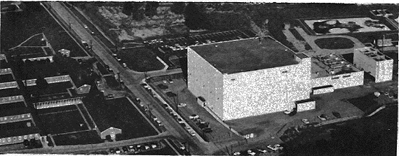 SAGE Direction Center, 29 K bytes
Fig. 1. A Sage Direction Center building contains power generation and computing
equipment, operational areas for directing sector operation, and office and maintenance
facilities. Data is transmitted to this center both automatically and by voice phone.
The center communicates with adjacent SAGE centers and transmits guidance data
to weapons under its control.
SECTORS AND DIRECTION CENTERS,
With SAGE, air-defense is conducted from about thirty direction centers located
throughout the United States (Figure 1). A center is responsible for air surveillance
and weapons employment over an area called a sector. Each center contains a
digital-computing system -- the AN/FSQ-7 -- containing almost 60,000 vacuum tubes.
Over one hundred Air Force officers and airmen within the center control
air-defense of the sector. Most of these men sit at consoles directly connected
to the computer where they receive filtered displays of the computer's storage
of system status data; they direct the computer through manual keyboards at
each console. The Boston Sector is typical; its Direction Center is located at
Stewart Air Force Base in New York. Its area of responsibility extends from
Maine on the north to Connecticut on the south; from New York on the west to
a point hundreds of miles off the sea coast on the east.
|
|
 SAGE DATA-PROCESSING
 SAGE INPUT-OUTPUT
The computer in the direction center can store over one-million bits of information representing weapons and surveillance status of the sector at one time (Figure 2). These bits represent thousands of different types of information. For example, the computer generates and stores positions and velocities of all aircraft; or it stores wind velocity at various locations and altitudes. Within the computer, a program of 75,000 instructions controls all automatic operations; input data is processed, aircraft are tracked, weapons are guided, outputs are generated. Each second, the computer can generate over 100,000 bits of digital information for display to Air Force operator consoles. Each operator receives cathode-ray tube displays which are tailored to his needs, and he may request additional information or send instructions to the computer by means of keyboard inputs on his console. Each second, the computer can generate thousands of bits of information for automatic digital transmission via telephone or teletype to weapons and missiles, to adjacent centers or higher headquarters, and to other installations within the sector.
How fast is this system? Obviously, response times from input-to-output vary with the task performed. Fastest response is required by automatic control functions (such as weapons guidance) and for man-machine communication (such as displays of requested information). For many of these functions, only several seconds are required from stimulus to response. For others, several minutes may elapse before the effects of new data are reflected throughout the system. We shall consider now, in somewhat more detail, the three major areas which comprise SAGE data processing. First, the sector or environment which contains the data sources or sinks coordinated by the direction center. Next, the manmachine component -- how the operators within the direction center are informed of the air situation and how they affect its progress. Finally, we shall describe the computing system which performs the automatic component of the direction center function.
THE SAGE SECTOR
The direction center communicates with over one-hundred adjacent
installations (figure 3). Air surveillance data is received from
several types of radars: Long range search and gap filler radars
located throughout the sector provide multiple coverage of the air
volume within the sector; picket ships, early warning (AFW) aircraft
and Texas Towers extend this coverage well beyond the coastline;
height finders supply altitude data. Within the direction center, this
data is converted by the computer to a single positional frame of reference
and is used to generate an up-to-date picture of the air situation.
Other inputs to the direction center include missile, weapons, and
airbase status; weather data; and flight plans of expected friendly
air activity. Such data, which is received from many installations
within and without the sector, is automatically processed by the computer
and used by direction center operational personnel to assist identification
of aircraft, employment of weapons, or selection of tactics.
The direction center computer communicates automatically and continuously with adjacent direction centers and command level headquarters in order to insure that air defense is coordinated smoothly between sectors and conducted intelligently over larger areas than a single sector. For example, an aircraft flies out of a sector; surveillance data from the center is automatically transmitted to the proper adjacent center in order to guarantee continuous tracking and interception. In this way, adjacent centers are continuously warning, informing, and acknowledging.
Finally, the direction center continuously transmits status, command, or guidance data to airborne interceptors and missiles or to related ground installations.
Three types of data transmission are used for both inputs and outputs. First, data sources or sinks which require high transmission rates communicate directly with the SAGE computer by means of digitally-coded data transmitted at 1300 pulses per second over voice-bandwidth telephone lines and radio channels. Typical applications of this type of channel are inputs from search radars and intercommunication between adjacent centers. Teletype provides a second channel which is slower but equally automatic. Input flight plans are transmitted from Air Movement Identification Services. Finally, voice telephone communications are used in cases where high automaticity is either unnecessary, too expensive, or not feasible. If such information must be entered into the computer, either punched cards or operator keyboard inputs are used.
All data sources and sinks in the sector operate asynchronously. Inputs from each source arrive at the direction center with very different average and peak rates. Each source is processed by a computer with a priority and sampling rate consistent with the role of the particular data in the overall air defense function. Likewise, the computer generates output messages with a frequency and timing which will insure adequate transmission of guidance and status data and yet which will make maximum use of finite phone-line and teletype capacity. One of the major functions of the SAGE computer is coordination and scheduling in real-time of sector inputs and outputs with tbe manual and automatic functions performed in the direction center.
THE MAN IN THE SYSTEM
Although SAGE has made many of the dataprocessing functions in a direction center
automatic, many tasks remain which are better performed by the man. Operators
can relay computer outputs by phone or radio to adjacent installations and weapons;
they can recognize certain patterns more rapidly and meaningfully than any
of our present computers and take appropriate action. Most important, operators
are required for tactical judgments such as aircraft identification or
weapons deployment and commitment. If a major advantage of the FQS-7 computer
is its ability to maintain and store a complete picture of the sector situation,
then an equally important advantage is that; the same computer can rapidly
summarize and filter this data for individual presentation to the more than
one hundred air force personnel who both assist and direct air defense operations.
The fourth floor of the center contains operational areas from which Air Force personnel supervise the computer and the sector.
Each of the major air-defense functions is supervised from a separate room: radar inputs, air surveillance, identification, weapon's control, operations analysis, training, simulation, and sector command (Figure 4)
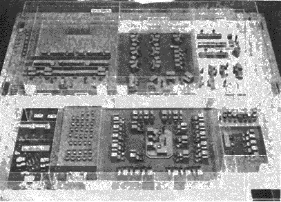 SAGE Fourth Floor, 29 K bytes
Fig. 4 The fourth floor of the direction center contains separate operational rooms
for air surveillance, identification, status input weapons assignment and control,
and command functions. Up to 50 operators are required in one room to man the
consoles which are directly connected to the computer.
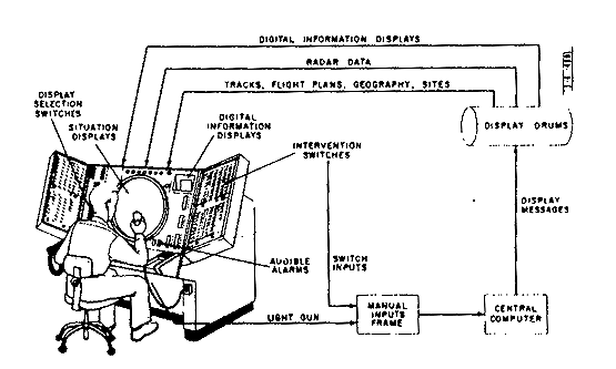
Each operator sits at a console which contains display and input facilities tailored to his responsibilities (Figure 5). The operators insert data into the computer by pushing keyboard buttons. (Figure 6). Each console is provided with an input capacity to the computer of 25 to 100 bits of information at one time: The total keyboard input capacity for all consoles is over four-thousand bits which are sampled by the computer every several seconds.
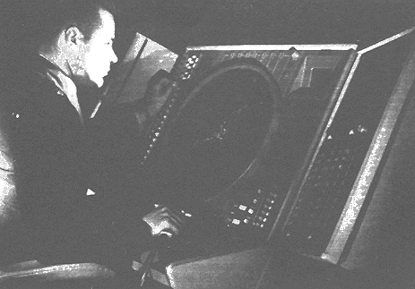 SAGE Operator, 33 K bytes
Fig. 5. Each operator sits at a console which contains display and input facilities tailored
to his responsibilities.
 SAGE Operator Console, 54 K bytes
Fig. 6. The operators insert data into the computer through keyboard actions.
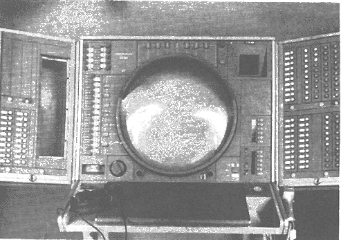
 SAGE Situation Display, 32 K bytes
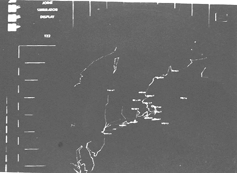
Fig. 7. Situation Display of New England coastline and adjacent installations.
A 19" Charactron (Developed by Hughes Products Co.) cathode-ray-tube displays geographically oriented data covering the whole or part of the sector (Figure 7). On this air situation display scope, the operator can view different categories of tracks or radar data, geographical boundaries, predicted interception points, or special displays generated by the computer to assist his decision.
Every two and one half seconds, the computer generates about two hundred different types of displays requiring up to 20,000 characters, 18,000 points and 5,000 lines. Some of these are always present on an operator's situation display. Others he may select. Some he may request the computer to prepare especially for his viewing. Finally, the computer can force very high priority displays for his attention.
The operators console can also contain a 4" Typotron (Developed by San Diego Division of Stromberg-Carlson (formerly Convair Division of General Dynamics) digital-display tube which is used to present status data such as weather conditions at several airbases or attention data which, for example, shows the operator why the computer rejected his action. (Figure 8). Sixty-three different characters are available in the Typotron. The FSQ-7 display system can display these characters at the rate of 10,000 characters every few seconds to all the digital display scopes.
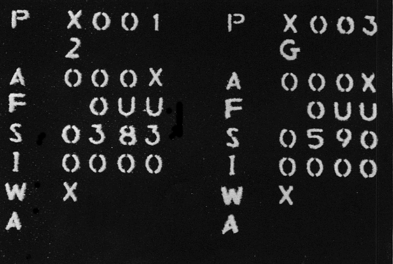 Typotron digital display,
33 K bytes
Typotron digital display,
33 K bytes
Fig. 8. Typotron digital display.
SAGE COMPUTING SYSTEM
The SAGE FSQ-7 computer occupies the entire second floor of the direction
center. About seventy frames containing almost 60,000 vacuum tubes are required
to handle all input-output data, to perform air-defense calculations and to
store system status data. In order to insure round-the-clock operation two
identical computers are required. These are located on opposite sides of the
floor with unduplicated input-output equipment and maintenance consoles
situated in between.
 Computer Overview, 33 K bytes
Fig. 9. Each of two identical computers includes the central computer which
performs all calculations, the 75,000 instructions air-defense program, and the
millions of bits of system status data. Both of the latter are stored on
auxiliary magnetic drums.
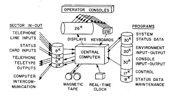
Figure 9 shows the logical organization of one of the two identical computers. Since only one of these computers performs the real-time air-defense function at any one time, we can discuss simplex processing before considering the problems of duplex operation.
The computer system consists of the following major components: A central computer, the air-defense computer programs, and the system status data stored on auxiliary magnetic drums. The central computer is buffered from all sector and console in-out equipment by magnetic drums (except for the console keyboard inputs which use a 4096-bit buffer core memory). Finally, a real-time clock and four magnetic tape units (used for simulated inputs and summary recorded outputs) complete the FSB-7 computing system.
The central computer is a general purpose, binary, parallel, single-address machine with 32-bit word length and a magnetic corememory of 8,192 words. The memory-cycle time is six microseconds. Each instruction uses one 32-bit~word and the effective operating rate is about 75,000 instructions per second. Four index registers are available for address modification. One unique feature of the central computer is the storage and manipulation of numerical quantities as two-dimensional vectors with two 16-bit components. In this way, a single sequence of instructions can simultaneously process both components of positional data, effectively doubling computing speed for this type of processing. Twelve magnetic drums, each with a capacity of 12,288 thirty-two bit words, are used for storage of system status data, system control programs and buffer in-out data. Under control of the central computer, data can be transferred in variable length blocks between these drums and core memory. The total drum storage capacity is about 150,000 32-bit words.
During an average one-second period the central computer transfers from twenty to fifty blocks of data, each containing 50 to 5000 words, between the central computer's core memory and the terminal devices. In order to insure maximum utilization of the central computer for air-defense processing and control, an in-out break feature is used. With this feature, calculations in the central computer continue during input-output operations; they are only interrupted for the one core memory cycle required to transfer a word between the core memory and the terminal device. The in-out break has proven very valuable since considerably more than 50% of real-time is required for input-output searching, waiting, and transferring.
The input-output buffering devices process in-out data independently of the central computer and so free the computer to do more complex air-defense processing. (Separate read-write heads are provided for the buffering equipment and for the central computer). In their buffering role, these devices can receive or transmit data while the computer is performing some unrelated function.
Consider, for example, the general manner in which input data from voice band-width phone lines is received. The serial 1,300 pulse-per second message is demodulated and stored in a shift register of appropriate length. When the complete message has been received, the message is shifted at a higher rate into a second shift register (whose length is a multiple of 32 bits), thus freeing the first register to receive another message. When the first empty register is located on the input buffer drum, parallel writing stores the word in 10 microseconds. A relative timing indicator is also stored on the drum with the message since the computer may not process the message for several seconds and since time of receipt at the direction center is often critical. The central computer can read this randomly stored data by requesting a block transfer of occupied slots only. Output messages are processed conversely. In a few milliseconds, the central computer can deposit (on the output buffer drum) a series of messages which will keep several phone lines busy for ten seconds.
 Man/Machine Communication,
33 K bytes
Man/Machine Communication,
33 K bytes
Fig. 10. Major means of communication between automatic equipment and
operating personnel.
The processing ability of the buffer devices is fully exploited in the display system (Figure 10). In this case, the central computer maintains a coded table on the buffer display drum. This table is interpreted and displayed by special purpose equipment each two and one half seconds at the appropriate console. The central computer can change any part the display at any time by rewriting only appropriate words on the drum.
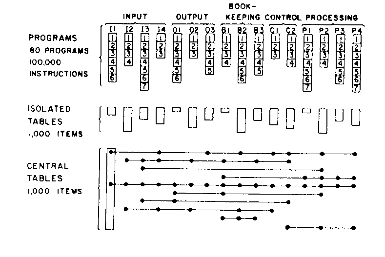 Static program organization,
33 K bytes
Static program organization,
33 K bytes
Fig. 11. Static program organization.
 Dynamic program organization,
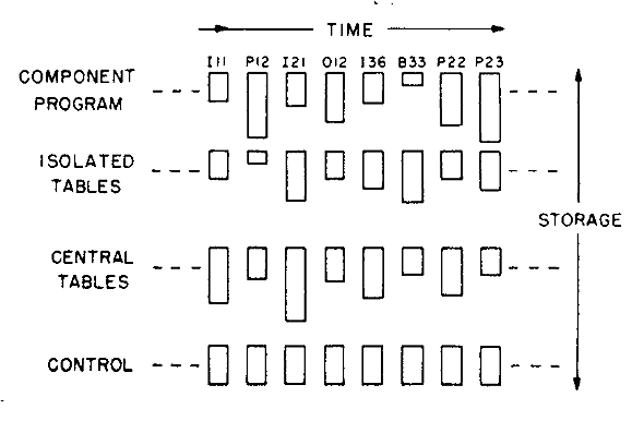
33 K bytes
Dynamic program organization,
33 K bytes
Fig. 12. Dynamic program organization.
The central computer performs air-defense processing in the following manner (see Figures 11 and 12). The buffer storage tables, the system status data and the system computer program are organized in hundreds of blocks -- each block consisting of from 25 to 4000 computer words. A short sequence control program in the central computer's core memory transfers appropriate program or data blocks into core memory, initiates processing, and then returns appropriate table blocks (but never programs) back to drum. To take advantage of the in-out break feature, operation of each air defense routine, is closely coordinated with operation of sequence control program so that programs and data are transferred during data processing.
By time-sharing the central computer, each of the air defense routines is operated at least once every minute -- many are operated every several seconds. One interesting feature is that the frequency of program operation is locked with real-time rather than allowed to vary as a function of load - during light load conditions the sequence control program will often "mark time" until the real-time clock indicates that the next operation should be repeated. Such synchronization with real-time simplifies many of the control and inputoutput functions without causing any degradation in system performance.
 Digital data transmission
equipment,
33 K bytes
Digital data transmission
equipment,
33 K bytes
Fig. 13. Digital data transmitted automatically to the direction center via
telephone lines can be selected for insertion into the computer at an input
patch panel.
 Magnetic Drums,
33 K bytes
Magnetic Drums,
33 K bytes
Fig. 14. Magnetic drums are used for buffer storage of input-output data, and storage
of system status data and computer programs. Twelve physical drums (six shown)
have capacity for almost 150,000 32 bit words. Half of this capacity is required
for storage of the real-time computer program.
RELIABILITY
One last aspect of the computing system remains to be discussed; namely, reliability.
As mentioned earlier, 24-hour-per-day uninterrupted operation of the
computing system was a requirement which could not be compromised. The FSQ-7
is a crucial link in the air defense chain - if the computing system stops,
the surveillance and control functions are interrupted, man and machine
throughout the sector lose vital communications, and the sector is without
air defense.
In order to insure continuous system operation, any component whose failure would cripple the system has been duplexed whenever possible. As a result, two complete, independent computers are provided - each with separate drums, central computers, input-output buffering devices, and magnetic tapes. Equipment associated with individual input-output channels is generally not duplicated: consoles, phone-line demodulators, shift registers, etc. Loss of one of these equipments would merely cause loss of some data and minor system degradation, rather than complete shut down of the direction center.
At any one time, one computer performs the air defense job -- this is the active computer. The standby machine may be operating in one of several modes: it may be down for repair (unscheduled maintenance time); it nay be undergoing routine preventive maintenance (marginal checking) or even assisting in the maintenance of other equipments within the sector.
The switchover process interchanges the roles of the computers: the standby machine goes active, the active machine goes to standby. Simplexed devices which had been connected to one machine are automatically transferred to the other and the air-defense program begins operation in the newly active machine. From an equipment point of view, switchover requires only a few seconds. However, all of the system status data which had been available before switchover must be available to the newly active computer. Otherwise, the entire air-situation picture would need to be regenerated and this would cripple sector operations as effectively as if both computers had stopped. Accordingly, the active machine transmits changes in the air situation data to the standby machine several times per minute via an intercommunication drum. Computer switchover is hardly noticeable to operating personnel.
Although the requirement for continuous operation is a stringent one, SAGE is less vulnerable than many other digital computer applications to transient errors in the FSQ-7. For most operations, the computer operates iteratively in a feed-back loop. In these applications, the system is self-correcting for all but a few improbable errors. Parity checking circuits in the input and output buffer equipment and in the computer memory system eliminate some data subject to transient errors.
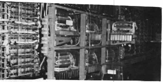
| Pages 12 and 13 of the original contain 6 photos of SAGES scenes. Although the photos are interesting, they do not provide any new technical information. They do provide a sense of enormous computers, many racks of equipment, many consoles, vast resources. |
-
B.W. Taylor, E.W. Veitch, and J. Wylen
Burroughs Corporation, Paoli, Pennsylvania
Presented at the Eastern Joint Computer Conference, December, 1957
Operation of the SAGE Duplex Computers
-
P.R. Vance, MIT Lincoln Laboratory, Lexington, Mass.
L.G. Dooley, Rand Corporation, Lexington, Mass.
C.W. Diss, IBM Corporation, Kingston, New York
Presented at the Eastern Joint Computer Conference, December, 1957
The Logical Design of the Digital Computer for the SAGE System
-
M.M. Astrahan, IBM Corporation, Kingston, New York
B. Housman, IBM Corporation, Kingston, New York
J.F. Jacobs, MIT Lincoln Laboratory, Lexington, Mass.
R.P. Mayer, MIT Lincoln Laboratory, Lexington, Mass.
W.H. Thomas, IBM Corporation, Kingston, New York
IBM Journal of Research and Development, Vol. 1, No, 1, January, 1957
Production of Large Computer Programs
-
H. D. Benington
Rand Corporation, Lexington, Mass.
Proceedings of the Symposium on Advanced Programming Methods for Digital Computers
Sponsored by the Navy Mathematical Computing Advisory panel
and the Office of Naval Research
Simulation in Large Digital Control Systems
-
D.R. Israel, MIT Lincoln Laboratory, Lexington, Mass.
Presented at the National Simulation Conference, Houston, Texas April, 1956
end of document
Updated February 11, 1999