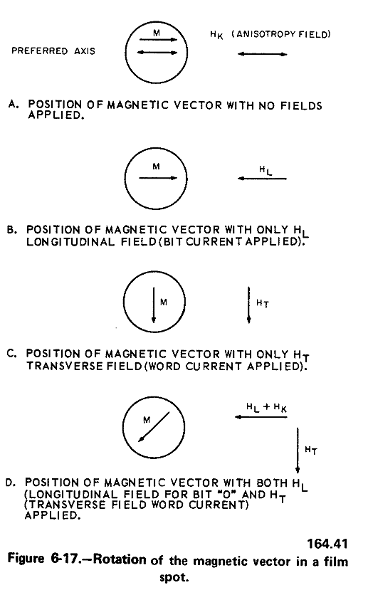
A magnetic field is applied parallel to the surface of the substrate during deposition. The film spots thus become easier to magnetize in a direction parallel to that in which the magnetic field was applied during the deposition process. This direction is known as the preferred direction; likewise, the axis of this magnetism is referred to as the preferred axis.
STORAGE

Thin film materials are well suited for storing binary
data since they have a stable state of magnetization in
each direction parallel to the preferred axis. The
double-headed arrow in the circle shown in figure 6-17A
is to be regarded as indicating the preferred axis.
When the direction of magnetization is caused to
rotate through 180 degrees (starting from the
preferred axis), there is first a torque which tries to
retain the magnetism along the preferred axis. If the
magnetizing force is sufficiently strong, the magnetism
will be shifted to a point perpendicular to the
preferred axis. Beyond this point, there is a forward
torque which causes the magnetism to be alined in the
material exactly 180° from the preferred axis. The
torque is caused by the field HK which is produced
during the deposition process. This field is called the
anisotropic field. (The word "anisotropic" is used to
describe the ability of the magnetic material to assume
different positions in response to the action of external
stimuli.)
If the magnetic stimulus is removed after the anisotropic field is formed, this field (HK) causes the magnetic vector to be alined parallel to the preferred axis. If a coercive force, HC, which is less than that required to switch the magnetization but produces a field parallel to the preferred axis is applied, no significant change results in the state of the magnetized material.
Applying only a transverse field, HT, (fig. 6-17B), i.e., a magnetic field perpendicular to the preferred axis, and which is stronger than HK, causes the magnetic state of the spot to be rotated 90° as shown in figure 6-17C. If fields are applied so that the vector sum of HL + HK is an active force on the spot, the position of the resultant magnetic vector will be as illustrated in figure 6-17D. If HT is then removed from the spot, the direction of the magnetization be- comes the same as that for HL. When HL is removed, the spot remains in the new state until HT is again applied. Thus, the direction of HL determines the direction of the stable state of magnetization of the film spot.
SWITCHING
Because a concentric magnetic field is pro- duced around a flow of current, it is possible to switch a film spot by passing current through drive lines that are placed in close proximity with the spot. The drive and sense lines (line array) are sometimes etched on Mylar sheets which are carefully aligned and attached to epoxy boards to give the required strength to the line array.

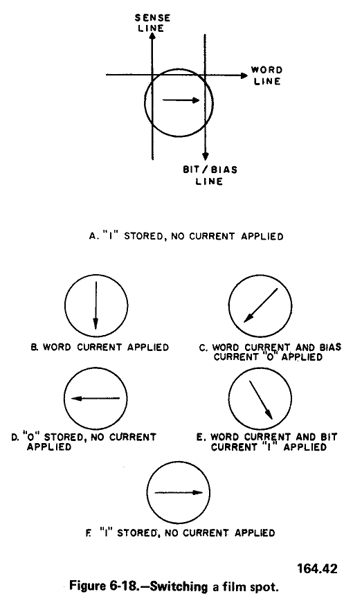
Figure 6-18A shows in simplified form a film
spot and the line array on one side of the spot.
An identical set of these lines is placed on the other
side of the film spot. The connectors for the line array
are wired in a manner such that the sense and bit lines
each produce one turn around the spot, and the word
lines produce two turns. (Bit lines are effective in
selecting a particular bit of a word. Word lines provide
a partial enable for a word section of the memory).
The arrow on the film spot in figure 6-18A shows the stable state magnetic vector with a "1" stored. If word current flows down the word lines, the magnetic vector rotates 90 degrees as shown in figure 6-18B. If bias current is applied to the bit lines, the magnetic vector rotates toward the "0" stable state as shown in figure 6-18C. After the word current is removed, the vector completes the 180-degree rotation from the "1" state. Thus, a "0" is stored as shown in figure 6-18D.
If a "1" is to be stored in the spot (see figures 6-18E and 6-18F) current applied to the bit lines is reversed. Thus, the magnetic field around the bit lines reverses and the magnetic vector is rotated toward the "1" state. If the word current and then the bit current are removed, the stable state of magnetization will represent a "1."
SENSING
The thin-film memory is a destructive readout memory; i.e., the reading of thin film spot (location) clears the contents of that address. During a readout, all of the addressed spots are switched toward the "0" state. The sharp change in the magnetic field around any spot causes a voltage to be induced in the sense lines. The magnitude of this voltage depends upon the change in the magnetic flux resulting from the switching process.
The output is read from the memory by ANDing a strobe pulse with the output from a sense amplifier (not shown) whenever a 1 is stored in the location being read. No output from the AND circuit indicates a "0" has been read. Figure 6-19 illustrates the timing relationships during readout.