Go to On Line Documents, Go to Go to Antique Computer home page


Disclaimer: This MANIAC II manual was OCRed, spellchecked and HTMLed (including links from Table of Contents to items) carefully, but must be considered to contain errors. The conversion should be accurate, baring undiscovered "I" for "1" and other substitutions that hopefully will not distract from the usefulness. Some questionable spelling in the original is tagged with [sp] . Charts were converted to .gif and .jpg images to eliminate this point of error introduction. Some inline itemization was made vertical for easier reading. Foot notes were moved to the referencing text and inclosed with brackets [].
Best Regards

Ed Thelen - ed@ed-thelen.org - August 7, 2000


click here to see Cover

size is 20 Kbytes


LEGAL NOTICE

This report was prepared as an account of Government sponsored work. Neither the United States, nor the Commission, nor any person acting on behalf of the Commission:
  1. Makes any warranty or representation, express or implied, with respect to the accuracy, completeness, or usefulness of the information contained in this report, or that the use of any information, apparatus, method, or process disclosed in this report may not infringe privately owned rights; or
  2. Assumes any liabilities with respect to the use of, or for damages resulting from the use of any information, apparatus, method, or process disclosed in this report.
As used in the above, "person acting on behalf of the Commission" includes any employee or contractor of the Commission to the extent that such employee or contractor prepares, handles or distributes, or provides access to, any information pursuant to his employment or contract with the Commission.

Printed in USA. Price 35 cents. Available from the

Office of Technical Services
U. S. Department of Commerce
Washington 25, D. C.


                                   LA-2083 
                                   PHYSICS (Distributed according to 
                                   TID-4500, 12th edition)

LOS ALAMOS SCIENTIFIC LABORATORY 
OF THE UNIVERSITY OF CALIFORNIA   LOS ALAMOS   NEW MEXICO

REPORT WRITTEN: October 1, 1956 
REPORT DISTRIBUTED:  Jan 30 1957


                        MANIAC II

Work done by:                          Report written by:
-------------                          ------------------
R. B. Lazarus                          R. B. Lazarus
N. Metropolis 
W. Orvedahl 
J. H. Richardson 
W. Spack, Jr.

     and

R. L. Bivins 
J. V. Caulfield 
I.  Krai
A. F. Maimberg 
G. T. McKinley 
R. E. Williamson


Contract W-7405-ENG. 36 with the U. S. Atomic Energy Commission


In accordance with the intention that Maniac II will undergo modification and improvement, this report has been spiral-bound to allow insertion of new and replacement pages.


FOREWORD

The original Maniac has been described at length in Los Alamos Scientific Laboratory Report LA-1725, and computers of its general type (e.g., IAS computer at Princeton, Illiac, IBM 701) are undoubtedly well known by most readers. The Laboratory's reasons for entering the field of computer design and contruction [sp] were, of course, obvious, since no electronic computers were then commercially available. Its reasons for continuing in the field and undertaking the design and construction of Maniac II were several, a few of which are as follows:
  1. Since the evidence for feasibility of large magnetic core storage was, at the time, rather weak. It seemed desirable to Investigate barrier grid storage.* [*Large magnetic core storage now does seem feasible. Barrier grid storage at present offers comparable speed at considerably lower cost.]
  2. Since commercial developments are not primarily guided by the needs of scientific computing as carried on in this Laboratory, it seemed wise to continue research which is primarily so guided.
  3. It seemed desirable to have a computer specifically designed to allow for electronic modification, both to incorporate new ideas and improvements and to facilitate certain mathematical researches best done electronically, rather than by coded program.

Maniac II is an improvement over the original Maniac by a factor of about five in basic speed and ten in size of internal memory. The effective speed increase is considerably greater, however, because of the inclusion of modern features, such as floating point and automatic address modification, and because of increased facilities for problem debugging and for manual intervention.


ACKNOWLEDGEMENT

The design and construction of Maniac H Involved a very great deal of assistance by a large number of people, in wiring and construction as well as in logical design. At the risk of sinning by omission, particular acknowledgment must be given to D. H. Bradford, M. A. Devaney, V. R. Gafke, V. E. Gardiner, A. M. Gustaflk, H. J. Hudgins, S. S. Larson, J. K. Rasmussen, M. T. Rotenberg, R. G. Schrandt, M. F. Shaffer, M. R. Storm, M. Tsingou, B. E. Walden, M. B. Wells, D. Williamson, E. D. Wilner, and D. F. Woods.


CONTENTS

. Page
Foreword 3
Acknowledgment 4
Introduction 7
1. General 9
2. Storage
Electrostatic
Sense Lights
Magnetic Tape
11
3. Information
Instruction Format
Operand Format
13
4. Control
Transfer Instructions
Breakpoint Transfers
Manual Transfers
15
5. Manual Operation
Control Panel
Display
Slow Automatic and Pedalling [sp]
Console Typewriter
19
6. Manual Intervention
Sense Lights
Purple Breakpoints
23
7. Special Indicators
Overflow
Insignificant Division
Exponent Spill
Illegal Address
Tilt
25
8. Stops
Stop Instructions
Fixed Point Division
Square Root
Printing
Reading
Magnetic Tape
27
9. Vocabulary
Notation
Instruction List
29
10. Input-Output
Photoelectric Reader
Magnetic Tape
Fast Printer
Fast Punch
Flexowriter
39
11. Programs 43
Appendix 45


INTRODUCTION

A summary of the material in this first report on Maniac II, together with an Indication of topics that may be expanded or supplemented in the future, follows:

  • Section 1, General, gives a brief description of the computer and its parts.

  • Section 2, Storage, describes the storage In terms of amount, speed, and checking facilities.

  • Section 3, Information, discusses the word formats for instructions and operands, including floating point numbers.

  • Section 4, Control, is concerned with the sequencing of instructions.

  • Section 5, Manual Operation, is perhaps disproportionately long because of the number of features peculiar to Maniac II.

  • Section 6, Manual Intervention, describes methods of changing the normal flow of a calculation by manual intervention.

  • Section 7, Special Indicators, discusses indicators that apply to both manual and automatic operation.

  • Section 8, Stops, mentions a few stops not covered elsewhere.

  • Section 9, Vocabulary, describes general features of the Maniac vocabulary and lists the actual instruction set.

  • Section 10, Input-Output, makes some remarks about present input-output and definitely is destined for future expansion.

  • Section 11, Programs, discusses aids to the programmer, both those already available and those definitely planned.
The report has been written primarily for those who are already familiar with electronic computers. It is to be expected that many questions will arise, and it would be appreciated if such questions, along with any suggestions and criticisms, were addressed to LASL Group T-7.


I. GENERAL

Maniac II is a high speed, general purpose, digital computer, with a random access, self-checking, electrostatic storage of 12,288 48-bit words. It is a binary, single address, parallel computer. It operates in fixed or floating point and has automatic address modification by means of three B registers (index registers). It is asynchronous and has no clock. Its speed is that appropriate to
  1. a memory cycle of 8 usec (microseconds),
  2. a basic add time of 6 usec, and
  3. a shift time of about 1.3 usec per stage.
The average multiply time is about 160 usec.

The arithmetic unit consists of three shifting registers, U, R, and S, and an adder, +. The Universal Register, U, holds the important operands and results. It is the accumulator and receives the result of addition or subtraction. It contains the multiplicand, the high order product, the high order dividend, the quotient, [That is, the rounded quotient; S receives the unrounded quotient.] and the argument and result of the square root order. The Remainder Register, R, holds the low order product and dividend, the remainder, and the extractor, and can occasionally be used for an extra-fast-access temporary storage location. The Storage Register, S, serves for communication with storage and input-output, as an extra register for holding operands, and for miscellaneous other uses as indicated.

The Instruction Register, I, receives instructions from the storage. Its Order Part, O, communicates with the decoding circuits; its B part selects an index register; and its Address Part, A, furnishes input to the B Adder, B+. The B Registers, Bl, B2, and B3, contain address modifiers (indices), which they gate into B+ whenever selected. B+ communicates with the memory address buses. The Control Counter, CC, also communicates with the address buses, and governs the fetching of instructions. CC can be set by B+ to effect transfers of control.

Input is via magnetic tape, paper tape, and a typewriter. (The last provides a written record of all manual changes.) Output is to magnetic tape, paper tape, the typewriter, and a fast line-printer. The input and output units are controlled by special instructions and/or by manual switches.

The 48-bit words in which information 16 stored are operands when brought into the arithmetic unit, and constitute pairs of instructions when brought into the Instruction Register. The fetching of instructions is governed by CC, which counts by half words unless set by a Transfer Control instruction, or unless caused to make a double count by certain special instructions. The fetching of operands (or the storing of results) is governed by the address part of the instruction involved, or by that address as modified by the contents of a B register. In the case of the magnetic tape and Fast Print orders, which require several operands stored at consecutive addresses, the contents of CC (the Control Counter) are dumped temporarily into the Pathfinder Register, PF, and CC is used to compute the required addresses. The primary function of PF, however, Is to receive the contents of CC whenever CC is about to be set by a Transfer Control instruction, and to make this Information available to the arithmetic unit.


2. STORAGE

The internal storage of Maniac II consists of two barrier grid cathode ray tubes per stage, with either 3072 or 6144 bits per tube. [The choice is made by a Full Memory-Half Memory Switch.]

In addition to the normal 48 pairs of tubes, there is a 49th pair which contains a parity check bit for each word in the storage. This bit is set whenever a word is written into the storage, and it is checked on each regeneration and on each fetch. If a 1 should be dropped or picked up, the Maniac would stop, displaying the address of the failure.

The regeneration time per word is about 8 usec. It takes about 50 msec (milliseconds) to regenerate the full memory, or 25 msec for half the memory. The consultation ratios are at least 100 for the full memory and about 1000 for the half memory. [The consultation ratio is the number of consultations allowed between regenerations.]

The memory cycle of the electrostatic memory is also about 8 usec. Under some circumstances, some of this time is covered by other useful work, such as clearing registers to zero.

The 14 Sense Lights, which will be discussed later, constitute storage positions for single bits of information (e.g., for combinations of yes-no decisions), which can be stored and read by the operator as well as by the Maniac.

There are two magnetic tape units, which can be used as external storage. The Maniac can transfer word blocks (records) of arbitrary length from the internal storage to the tapes, and vice versa, at a rate of about 600 words per second. The parity check bit for each word is recorded on the tape and checked on Tape Head. A word sum of each record is left in U after reading or writing a record, primarily for record identification.


3. INFORMATION

A word can be an instruction, an operand, or both, according to the use which is made of it. For example, a word ordering the multiplication of the contents of U by the contents of, say, memory address 0100 would be an instruction, while the word at address 0100 would be an operand.

More specifically, an instructional word consists of two half-word instructions, each having six tetrads of four bits each (see Fig. 1). The first two tetrads of an instruction constitute an order, according to the vocabulary given below. The last four tetrads (16 bits) furnish an address (or some other number relevant to the particular order) in the following way: The first two bits select a B register (BO, the zeroth B register, is a mythical register defined as containing 0 at all times). The contents of the last 14 bits are then added to the contents of the selected B register to furnish the Effective Address. [Note that some instructions, such as (R) to U, are completely specified by the order tetrads; for these, the last four tetrads are ignored.]

An operand is by nature simply a collection of 48 bits of information, which can be interpreted and modified in any finite way by the available vocabulary. In the majority of cases, however, it 13 treated as a number. The bits of a number, or the stages of an arithmetic register holding a number, are designated as shown in Fig. 2.

The binary point is between bits 0 and 1. Stages 1 through 43 hold a positive fraction, |x|, whose range is 0 <= |x| <= 1-2-43. Stage 0 holds a sign for this fraction (0 for plus, 1 for minus).

Stages -3 through -1 hold a positive integer, |e|, and stage -4 holds a sign for this integer. This signed integer, e, is the exponent of the Maniac's floating base, which is 216 = 65,536.

Thus a full number, represented by an exponent, e, and a fraction, x is

N = 216ex

The range, for a single word, non-zero number, N, is

2-155 < N < 2112,

or, approximately,

2*10-47 < N < 5*1033.

The Maniac's large base permits a considerable increase in the speed of floating point arithmetic. Although such a large base implies the possibility of as many as 15 lead zeros, the large word size of 48 bits guarantees adequate significance.

A number N = (e,x), for which the exponent e = 0, is equal to the fraction, x. and may be considered fully equivalent to a fixed point number. The fact that floating and fixed point numbers have identical fraction bits allows a considerable saving in computer hardware. The saving is possible because, in many instances, the Maniac need not distinguish between fixed point operations and floating point operations which operate on numbers having zero exponents.


4. CONTROL

Control of the Maniac, for normal operation, is effected by a stored program. A problem to be solved must first be put in terms of the Maniac's vocabulary. The appropriate instructions must then be coded, and the coded instructions put into the internal storage, along with the necessary coded or numerical input data. (A large part of this work can be done by the Maniac, using translation and assembly routines.) The control is then sent to the first instruction.

After executing any instruction (other than Stop), the Maniac fetches another instruction into I (the Instruction Register) from a location specified by CC. Unless CC is specially set to a new address, it counts by half-words and causes the fetching of sequentially stored instructions. [Exceptions to this can occur on Sense and on Count-and-Compare, where CC may be made to count twice (skip) before the next instruction is fetched.] The sequencing of instructions is the same under automatic and manual operation, provided the manual operation consists merely in stepping through the program.

CC can be specially set to a new address in three ways:
  • by a Transfer Control instruction,
  • by a breakpoint transfer, or manually,
  • by using the Control Counter Switches.

A Transfer Control instruction (for which the conditions, if any, obtain) involves three steps. First, CC makes an ordinary half-word count, thus producing the address of the next instruction in sequence, i.e., the instruction which would be fetched next if the transfer did not take place. Second, this address is placed in the Pathfinder Register, PF, where it is available to the arithmetic unit (In particular, available for return from subroutines, etc.). Third, the Control Counter is set to the address contained in the Transfer Control instruction (or to that address modified by the contents of a B register) and a new instruction is fetched from that address.

Breakpoint transfers involve the interaction of special switches, set by the operator, with special tags (real or virtual) on instructions in the storage. There are two types of breakpoint, called red and purple. A tag for a red breakpoint is real, and it is a 0 placed in the first bit position of the first order tetrad. Thus the order AB, for example, becomes 2B if tagged with a red breakpoint, since the tetrad A becomes 2 when its first bit is set to 0.

The tag for a purple breakpoint is virtual, only one instruction at a time can be tagged with a purple breakpoint, and the tagging Is done by setting the half-word storage location of the instruction on a set of Purple Breakpoint Switches.

There are two three-position Breakpoint Switches (one for each color of breakpoint), the three positions being Off, Stop, and Transfer. If a switch is in the Off position, then all tags of that kind are completely ignored. If a switch is in the Stop position, then the Maniac stops after performing any instruction with the corresponding kind of tag, without fetching the next Instruction. If a switch is in the Transfer position, then the Maniac effectively Inserts, after any appropriately tagged instruction, an Unconditional Transfer Control instruction, with an effective address equal to the address set on the CC Switches (see below). In other words, after performing a tagged order, the Maniac sets CC to the address on the CC switches, leaving stored in PF the usual record of where it was about to go. (Exception: If a Transfer Control instruction has a tag corresponding to a switch in the Transfer position, the Maniac acts as though the switch were in the Stop position.)

Manual setting of the Control Counter is effected by pushing the CC Set Switch on the control panel. CC sets to the address on the CC Switches. For this manual setting, the Manual-Automatic Switch must be on Manual; if it is on Automatic, then the CC Set Switch is Inoperative.


MANIAC II Control Panel

size = 24 Kbytes


5. MANUAL OPERATION

The facilities for manual operation of the Maniac are on the Operator's Console. The console consists of a desk, facing a control panel and almost surrounded by the input-output equipment. The panel (see facing diagram) contains rows of lights displaying the contents of the various registers, rows of switches for setting certain registers, and an assortment of display lights and special switches for a variety of purposes. S, R, and U are displayed at the top. On the right side are I, B+ (Effective Address), the selected B Register, PF, and the Parity Check Register (Tilt). On the left side are CC, with the CC Switches and the Purple Breakpoint Switches, the Sense Lights, and the Sense Switches. In the middle are the Red Breakpoint Switch, the Overflow and Insignificant Division Lights, the Exponent Spill Lights, the Allow Negative Exponent Spill Switch, and the Tilt Light, which indicates parity check failure. On the right, at the bottom, are three switches for displaying the B Register contents. In the center, at the bottom, are the Manual-Automatic Switch, the Fetch and Perform Switches, with their indicators, and the Slow Automatic Switch.

The three rows of 48 lights at the top of the control panel display the current binary contents of S, R, and U. They are divided for easy reading in tetrads. Below this and to the right is a row of 24 lights displaying the current instruction. Whether or not this instruction has been performed is indicated by lights over the Fetch and Perform Switches (see below). Immediately below this are two rows of 14 lights. The lower row displays the current contents of the B Register that is selected by the current instruction.
[Note that this is the B Register selected by the B bits; in the case of Count B, etc., it is not the B Register being modified.]

The upper row of 14 displays the effective address, which is the sum of the address and the index, i.e., the sum of the number directly above and the number directly below. Below the B Register lights is a row of 15 lights displaying the address-plus-one-half of the last transfer performed (due either to a transfer instruction or to a breakpoint transfer).
[Exception: The contents of PF are destroyed by Fast Print and some magnetic tape instructions.]

All these lights display the same information regardless of the position of the Manual-Automatic Switch.

The bottom row of 14 lights, on the right, is normally dark. It displays the address of the last parity error found, if that error still exists (i.e., the lights go out when the error is corrected).

In the bottom right corner are the three B Display Switches (self restoring). When one of these is held down, the display will be as though the corresponding B Register had been selected by the current instruction, regardless of the actual selection.
[If two or more switches are depressed simultaneously, no useful information will, in general, be obtained, although, of course, no harm will be done.]
These switches are inoperative on Automatic.

The row of 15 Purple Breakpoint switches at left center is used for tagging an instruction with a Purple Breakpoint, by setting up the instruction's half-word location; the three-position switch to the left of this row governs the action of the breakpoint. The row of 15 lights below the Purple Breakpoint Switches displays the current contents of CC (namely, the halfword address of the next instruction to be fetched). Below the CC Lights are the 15 CC Switches, plus a Set Switch on the left. If the Set Switch is depressed, the Control Counter will be set to the half-word address on the CC Switches. These CC Switches also contain the half-word address to which all breakpoint transfers will go. (Note: The CC Set Switch is inoperative on Automatic.)

Below these are the 14 Sense Lights and the 14 Sense Switches, and to the right are the special indicators and reset switches. These will be discussed below.

To the right of the Sense Lights are the Slow Automatic Switch, and the Fetch and Perform Switches (with their indicators). These switches are inoperative on Automatic, except as noted below.

The following statements apply when the Maniac is on Manual:
  • When the self-restoring Slow Automatic Switch is depressed, the program will flow as on Automatic, but at a reduced rate of about 20 instructions per second.
  • When the Fetch Indicator is on, the instruction in I has not yet been performed.
  • When the Perform Indicator is on, the instruction in I has already been performed.
In either event, depressing the Fetch Switch will cause the fetching of an instruction from the location contained in CC, and depressing the Perform Switch will cause the instruction currently in I to be performed. Normal sequencing can be maintained only by the alternate action of the two switches.
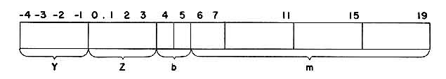
Whenever the Manual-Automatic Switch is returned to Automatic, either the Fetch Switch or the Perform Switch may be used once, after which both switches become inoperative until the Manual-Automatic Switch is returned to Manual. If a stop occurs while the Maniac is on Automatic, automatic operation can be continued only by switching to Manual, fetching or performing one or more times, and then returning to Automatic. It is hoped that this will discourage the use of intentional stops.


6. MANUAL INTERVENTION

To enter manually full words of information, or to perform manually some minor program without storing it in the memory, one uses the console Flexowriter and its three-position switch. This switch must be in Neutral for the Maniac to run on Automatic. When the Maniac is on Manual, the switch can be put in the I position or the S position. Then striking a key on the Flexowriter will shift the corresponding tetrad into I or S, respectively, from the right. After the required information has been typed and the switch returned to Neutral, the Perform switch may be used to execute the instruction. Note that a typed record will be made of all such manual changes.

The 14 Sense Lights were mentioned in Section 2, Storage. These lights are single-bit storages. They can be set independently, with the three-position self-restoring Sense Switches, to 1 (on) or 0 (off) by the operator, while on Manual or Automatic. They can, of course, be read by the operator, from their on or off status. They can also be set either way, singly or in any combination, by the Maniac. Lastly, they can be tested by the Maniac, using an instruction which asks whether or not a given combination of lights consists entirely of l's. By means of these lights, then, up to 14 bits of information at a time can be exchanged between the Maniac and the operator, without interrupting the calculation.

Purple Breakpoint tagging, as well as setting of the three-position breakpoint switches, can be accomplished on Manual or on Automatic. This provides another method of changing the normal flow of a calculation by manual intervention.


7. SPECIAL INDICATORS

The Overflow Indicator lights whenever there is a spill due to fixed point addition or subtraction, to a left shift (other than Logical Left) or to a Round. It is extinguished by a Transfer on Overflow instruction. When on Manual, it can also be extinguished by its own reset switch.

The Insignificant Division Indicator lights whenever a legal floating point division is performed wherein the denominator fraction remains less than the numerator fraction even after a 32 place displacement. The indicator is for information only. It can be extinguished by its reset switch on Manual or on Automatic.

The Positive Exponent Spill Indicator lights whenever the exponent exceeds +7. On Manual, there will be no effect other than the indicator's lighting. If the operator continues pedalling without attending to the spill, the program will continue, using an erroneous number. On Automatic, the Maniac will stop before fetching the next instruction after the spill occurs. The operator must switch to Manual before he can continue. The light can be extinguished by its reset switch, but only on Manual.

The Negative Exponent Spill Indicator lights whenever the exponent falls below -7. If the Allow NES Switch is on Stop, then the situation is completely analogous to that of positive exponent spill. If, however, the Allow NES Switch is on Allow, then the indicator is for information only. The Maniac will replace the number with the spilled exponent by the number (-7,0), which has all the correct properties of zero, and continue normal operation without interruption. The light can be extinguished, in any case, by its reset switch, but only on Manual.

When the memory is asked to read from or write into an illegal address (3000 through 3FFF, for Full Memory, and 1800 through 3FFF, for Half Memory), the Illegal Address Indicator lights, and the memory control sets to interpret all "writes" as "reads". On Automatic, the Maniac stops after trying to complete performance of the order. The reset switch, operative only on Manual, will extinguish the indicator, and reset the memory control.

The Tilt Indicator lights whenever a parity error is found in the memory. On Automatic, the Maniac will stop after performing the current instruction. The indicator can be extinguished by its reset switch, but only on Manual.


8. STOPS

In addition to the stops already mentioned (switching to Manual, breakpoint stops, and stops associated with indicators on the Control Panel), there are the stops caused by Stop Instructions and a few more error-type stops not associated with special indicators.

A Stop Instruction is, by definition, any instruction with order tetrads not defined in the vocabulary. One can continue after such a stop in the way described at the end of Section 5, Manual Operation.

A Fixed Point Division Stop occurs, on Automatic, when a fixed point division is ordered which would yield a rounded quotient, q, such that |q| > 1. This stop can easily be identified by the presence in I of a Fixed Divide Instruction (D8). Continuation is as with stop instructions.

A Square Root Stop occurs, on Automatic, when a square root of a negative number is ordered. This stop can easily be identified by the presence in I of a Square Root Instruction (DA) together with the presence in U of a negative number. Continuation is as above.

(Note: On Manual, the only indication given of these two stops is that the Perform Indicator will not come on, since the Maniac is unable to perform the instructions. Maniac stops are in general simply fetch inhibitions, which have no meaning on Manual.)

There are a few other stops, associated with input-output equipment's not being ready.

If an improper print matrix (i.e., a matrix calling for more than one character in the same column) is addressed by a Fast Print instruction, the Maniac stops with the order (94) still in 1. If a Fast Print instruction is given when the printer has run out of paper, the Maniac also stops, this time before performing the order.

If a Read Word or Read Hexad instruction is given when no punched tape is in the Reader, the Maniac does not actually sense the error but believes that it is just a long time between sprocket holes. An experienced operator will be able to insert the tape and allow the Maniac to take off without interruption, but a more conservative procedure would be to switch to Manual, put in any tape to allow the Maniac to complete performance of the order, and then position the tape properly and Perform again.

If any magnetic tape instruction is given when there is no tape on the appropriate unit, the Maniac stops. After switching to Manual, one may install the tape and Perform, or else one may skip the instruction by Fetching.

For stops occurring due to illegal addresses in connection with magnetic tape orders or due to Read Tape instructions specifying improper record lengths, see Section 10, Input-Output.

No stop occurs on Fast Punch, if there is no tape, or on Flexowrite, [sp] if there is no paper in the typewriter.


9. VOCABULARY Any vocabulary list necessarily involves a compromise between brevity and completeness. This is particularly true as regards secondary changes in register contents, changes not of interest in straightforward programming. It is also true in regard to stops which may occur during the performance of an instruction, such as those due to exponent spill. Since an Appendix to this report describes in detail the secondary register changes and since preceding sections of this report describe the various stops, the following vocabulary list leans toward brevity.

Before giving this list, it will be helpful to define some abbreviated notation.

The instruction notation YZ b m refers as follows to the 24 bits which constitute an instruction:

Fig. 3

When b and m are not relevant for a particular instruction, they are replaced by dashes.

Bits -4 through 3 are assigned to the two order tetrads. Bits 4 and 5, when relevant, govern the selection of a B Register.

The letter X is used to represent the sum of the 14 bit number m and the 14 bit number contained in the bth index register [with the convention that the (mythical) zeroth index register always contains 0]. X is the effective address or other relevant number referred to in Section 3, Information.

The letters U, R, and S stand, as before, for the Universal, Remainder, and Storage Registers, respectively. When necessary or helpful to distinguish stages 0 through 43 of a register from the entire register (-4 through 43), the notation U', R', or S' is used. MU, MR, and MS are used to denote stages 1 through 43 of U, R, and S (these are the stages which hold the magnitude of the fraction part of a number). The notation UR stands for the effective double length register in which stages I through 43 of R are taken to be an extension to the right of U. PF stands for the Pathfinder Register.

Parentheses are used to denote "the contents of" or "the information stored at". For example, (U) means the word in the Universal Register, and (5-19U) means the contents of stages 5 through 19 of U. An arrow (->) is used for "replaces" or "replace" (or occasionally for "to"). Thus (U) -> (X) means that the contents of U replace the contents of X, i.e., store (U) at address X.

S0, referred to in orders B5 through BB, denotes the double address positions 6-19 and 30-43. It must ,be noted, however, that the Substitute Address instructions C4 through C7 substitute the contents of stages 3 and 6-19, for the left address, and stages 27 and 30-43, for the right address. This is because of the need to substitute half-word addresses into the Transfer instructions C8 through CF.

The reader should refer to the subsection on Transfer Control instructions in Section 4 for the details of the Transfer instructions. Note that the address in PF, after a transfer, is the normal return for a basic linkage, and address substitution from PF is the normal method of setting an exit. This exit setting will probably be the only use made of the substitution instructions in straightforward programming of mathematical problems. It should be added that the programmer, coding in conventional descriptive form may ignore the left-right, half-word instruction difficulties, which will be taken care of by the assembly routine.

Since a complete verbal description of Shift instructions is always long-winded, the diagram facing the descriptions of the Shift instructions in the vocabulary list may be more useful than the descriptions themselves.

Page 31 instructions, about 25 K Bytes
Page 32 instructions, about 25 K Bytes
Page 33 instructions, about 25 K Bytes
Page 34 instructions, about 25 K Bytes
Page 35 instructions, about 25 K Bytes
Page 36 instructions, about 25 K Bytes
Page 37 instructions, about 25 K Bytes


10. INPUT-OUTPUT

Information can be put into the Maniac by means of the photoelectric reader, the magnetic tape units, and the Flexowriter. The Flexowriter can enter information only under the control of the operator. The magnetic tape units can enter information only under the control of the Maniac. The reader can be used both ways.

Output from the Maniac is of four forms;
  • recording on magnetic tape,
  • printing on the Flexowriter,
  • punching paper tape on the fast punch,
  • and printing on the fast printer.

Photoelectric Reader. The reader transfers information to the storage register, S, from seven-hole punched paper tape. For Load and Read Word, only five holes are sensed. For Read Hexad, all seven holes are sensed. The fifth and seventh holes, in the respective cases, are for control only.

Maniac control of the reader is by the two Read instructions. Read Hexad shifts six bits into the right of S, from the next column on the paper tape, and then stores (S) at X. Read Word shifts tetrads into the right of S, for each column on the paper tape, until the reader encounters a space indication, at which time (S) is stored at X.

Operator control of the reader is by a Load Switch, which causes the first word on the tape to be stored at the address indicated by the CC Switches, and then causes successive words to be stored sequentially. The process is stopped by a stop code (see Fig. 4), and leaves CC set to the next address, i.e., the address just past the last one loaded.


Fig. 4

Magnetic Tape. The magnetic tape units for Maniac II are designed primarily for the loading of programs, and the recording of restart records and incompletely processed results. Their use as external memory is secondary. For this reason, primary consideration is given to the avoidance of human and machine errors in the process of recording.

In order that timing considerations may be handled by the Maniac internally, the Read and Write instructions are full word instructions and contain all information necessary for reading or writing an entire record.

The Order Parts specify Write, Read, or Read Backwards, and also specify the tape unit to be selected. This information is given redundantly in both half-words, to avoid accidental tape instructions, e.g., to avoid writing on tape zero by transferring to the number (—7, —1/2).

The B and Address Parts in the two half-words specify first and last word addresses for the record. If a Read instruction finds a record of the wrong length, the Maniac will stop. No words will ever be stored in the memory outside the interval specified by the two addresses, and the tape itself will never stop except at the end of a record.

If the last word address is itself an illegal address or is not greater than the first word address, then an illegal address is presented to the memory sometime during the course of performing the tape instruction. When this happens, the Illegal Address Indicator lights and the memory control sets to interpret all "writes" as "reads". The Maniac stops after doing what it can, under the circumstances, to complete performance of the instruction.

The time needed to read or write a record is about 1.5 msec per word, plus a total of 15 msec for start and stop.

The Advance Tape and Backspace Tape instructions cause X records to be skipped in the appropriate direction. The tape moves at the same speed as when reading or writing, but the Maniac is not held up unless it addresses the same tape again before all the records have been skipped.

A photo cell opposite the magnetic head permits automatic detection of reflective marks at the tape ends and of absence of tape.

Fast Printer. The fast printer prints one line at a time, the line being 48 characters long. The available characters are 0, 1, 2, 3, 4, 5, 6, 7, 8, 9, A, B, C, D, E, F,-, ., *, columns in which no character is printed remain blank. In order to print a line, a print matrix must be formed in storage, as described below. A large variety of programs for this purpose are available in the Maniac library; the ordinary programmer will never need come to grips with the problem.

The printer consists of a solid print cylinder equivalent to 48 print wheels fixed to a common axis, each wheel containing two sets of the above characters. Each set of characters occupies a half circumference. A series of connected paper forms is fed by synchronized sprocket feed between the print cylinder and a set of 48 hammers, with an inked ribbon between the paper and the print cylinder. The cylinder revolves at 900 rpm.

The print matrix occupies 19 words of memory, these words being in one-to-one correspondence with the 19 allowed characters. For each word, there is a one-to-one correspondence between the 48 bits and the 48 columns, with a 1 meaning print. As each row of characters on the print cylinder goes by, the Fast Print instruction consults the appropriate matrix word and triggers the hammers in the indicated columns.

When a Fast Print Instruction is given, the Maniac waits for up to a half revolution (i.e., up to 33 msec), until the beginning of a character set comes opposite the hammers. Then the execution of the instruction takes 33 msec. It is then too late to catch the other character set, so the next 33 msec is available for calculation, even if the maximum printing rate of 15 lines per second is desired. If 33 msec is insufficient for the job at hand, then 67 msec may be used, and the printing rate will drop to 10 lines per second. In general, if 33n msec is required for calculation between Fast Print instructions, then the printing rate will be 30/(n+l) lines per second, for any integral n.

As mentioned in Section 8, Stops, the printer stops if it runs out of paper or if a print matrix specifies more than one character in a column.

Since blank columns (and blank lines) can be produced by omitting l's in the print matrix, no format control is really necessary, but the following is provided, for speed and convenience.

A two-position switch selects single or double spacing of lines. This spacing is accomplished during the 33 msec following each Fast Print instruction, and in no way interferes with any time considerations.

A seven-position Channel Selection Switch selects a channel on a format control tape which is synchronized with the sprocket feed mechanism. The tape forms a loop whose circumference must correspond to the length of the form being used. When a Space Fast Printer instruction is given, the form advances, at 100 lines per second, until a hole is sensed in the selected channel of the format control tape. The Maniac is held up a maximum of 33 msec, unless it addresses the printer again before the advance has been completed.

An eighth channel on the format control tape causes an end-of-page skip, independently of any instructions.

Channel I on the format control tape is tied to a Restore Button, which effectively gives a Space Fast Printer instruction with Channel 1 selected. Normally, Channel 1 is for full page skip, and the Restore Button causes advance to the top of the next form.

Manual advance of the paper by any number of lines is also possible, for the convenience of those impatient to see the latest results.

The printing is five characters and six lines to the inch. The normal forms are 11 x 12-27/32 inches wide, with two horizontal rulings to the inch, but adaptation to other forms is fairly easy (unfortunately, the maximum allowable width is slightly less than the width of the forms currently in use on the IBM 704's). Two-part forms, with carbon paper, are available, but a slight clearance adjustment is required.

Fast Punch. Punching onto paper tape can be accomplished with the Punch Word instruction, at 240 msec per word, or with the Punch Hexad instruction, at 33 msec per hexad.

Flexowriter. The use of the Flexowriter for input has been described in Section 6, Manual Intervention. Output is via the Flexowrite instruction, which causes printing of a word in storage as a 12 character word, each character being determined by the corresponding tetrad. The rate is about 1 sec per word.

For increased life, the motors of all input-output units are automatically shut off whenever the unit remains unused for more than a certain prescribed length of time. However, these prescribed intervals are at least a hundred times as long as the unit's start-up time, so that no appreciable losses can occur.


II. PROGRAMS

    Aids to the programmer can conveniently be divided into three classes:
  • Subroutines,
  • Helper Routines,
  • and Assembly Routines.

Subroutines. Subroutines are common routines which are prepared once and for all and put into a form suitable for incorporation into new problems with a minimum of effort. Most of them are either Print Subroutines or Function Subroutines. Descriptions and summary lists of all subroutines will be published from time to time. At the present writing, the only unusual subroutine is for the function f(x, y) = xy where x and y are arbitrary floating point numbers, which has the feature that the computing time depends on a specification of the number of significant bits in the fractional part of y.

Helper Routines. Helper routines include all debugging aids, as well as routines for data manipulation not incorporated in the main code. Examples of the former are the various monitoring or tracing routines, especially the Breakpoint Monitors, which print interpretations of breakpointed instructions while running at full speed through nonbreakpointed instructions, and the Dynamic Single-Address Search, a fully supervisory routine which looks for a particular effective address. Examples of the latter are assorted block prints, conversion routines, and block clearing routines.

Helper Routines are on file near the Maniac, in the form of absolute codes on paper tape. Descriptions and summary lists will be published from time to time.

Assembly Routines. Assembly Routines are designed to create absolute codes, ready for running, from some conventionalized statement of the problem other than an absolute code. The eventual goal is to permit the conventionalized statement to be as close as possible to the original statement of the problem in ordinary mathematical language. Research in this direction is in progress, and it is primarily for this purpose that the hexad facilities have been included, to increase the number of distinct characters simply transmittible to the Maniac. However, no routines are currently available which are in any sense formula translating routines.

The Assembly Routine which has been prepared for Maniac II requires for its input a statement of the problem which is, indeed, very close in form and sequence to an absolute code. However, references by one part of the problem statement to another part, or to data, are in more natural terms, and ignore absolute machine locations. Further advantages are:
  1. B selection is not mixed in with addressing.
  2. Subroutines can be incorporated with great ease.
  3. The half-word nature of instructions can be ignored.
  4. Problem modifications can be accomplished with a minimum of perturbation.
  5. Certain coding blunders can be detected automatically.

Aids to the programmer probably will tend in the direction of general purpose routines with assorted options, controlled by sense switches. For example, a simple problem, can be put through the Assembly Routine and run immediately, with code print-out inhibited.


APPENDIX

REGISTER CONTENTS UPON LEGAL COMPLETION OF ORDERS

Sometimes, in programming, it is helpful to know the final contents of registers other than the one primarily involved in any given order. The accompanying table supplies this information (i.e., the register contents upon completion of an order) for all orders of Maniac II except input and output. We have not tabulated the register contents remaining after the machine stops that occur as a result of illegal operations on numbers since they are not of great use in coding (as opposed to debugging) and since they may be very complicated. It is intended that this table should supplement, rather than replace, the vocabulary description.

In most orders, the change in the I and B registers is uninteresting or obvious, or both; hence, only U, R, and S have been tabulated. Each of these registers is broken up into three parts:
E The exponent bits (—4 to —1)
ó The sign bit (0)
M The unsigned fraction, or magnitude, bits (1 - 43).


Subdivisions of a binary number considered as floating-point

The contents of the registers upon completion of an order are, for the most part, described in terms of the contents at this same time of other registers, or of the appropriately B-modified memory location addressed by the order. For this latter, the symbol m is used. Thus, if the entry EU occurs in the E column of R, one should read this as: "The contents of the exponent-bits of R at the completion of this order are identical to the contents of the exponent bits of U at this time." Or, if in the M column of the S register is found the notation Mm, this says: "The contents of the magnitude bits of S upon completion of this order will be identical to the final contents of the magnitude bits of the appropriately B-modified memory location addressed by this order."

It frequently happens that the contents of a part of a register are unchanged by the performance of an order. This state of affairs is indicated by a dash (—) in the appropriate spot in the table.

Occasionally, reference must be made to the contents of some portion of a register prior to the performance of the order. A prime following the appropriate symbol signifies this. Thus, EU' designates the original contents of the exponent-bits of U.

The performance of some orders leaves the ones-complement, or reflection, of a number in some portion of a register. A bar over the relevant symbol denotes this. Thus,
  if       óm = 1,
           __
  then     óm = 0,

  or if    MR = 101110011. ...... 101, 
           __
  then     MR = 010001100.......010.

The character 0 implies that every bit associated with the column in which it is found is a zero. Similarly, 1 implies all ones.

In a few cases, an actual binary number is written out, and, elsewhere, a signed decimal number has been used to indicate the contents of a portion of a register.

The symbol a is frequently used to refer to the answer obtained by performance of an order that is, the primary result of the order. Usually the significance is obvious (thus, in a multiply, óa is 0 or 1, as the signs of the factors are like or unlike). In case of doubt, one must appeal to the vocabulary description.

SUMMARY OF MORE IMPORTANT SYMBOLS USED

U	Universal register 

R	R register 

S	S register 

m	Appropriate memory location     \  
                                        |
E	Exponent bits (-4 through 1)   |  after completion of 
                                        |  the order
ó	Sign bit (0)                    |
                                        |
M	Magnitude bits (1-43)           /

--	Contents unchanged

a	Answer i.e., primary result of operation 
_
Z	Reflection of Z, any Z.

Z'	Contents of Z before the order was performed.

Page 48 register contents, about 25 K Bytes
Page 49 register contents, about 25 K Bytes
Page 50 register contents, about 25 K Bytes
Page 51 register contents, about 25 K Bytes
Page 52 register contents, about 25 K Bytes
Page 53 register contents, about 25 K Bytes