| Back to projects |
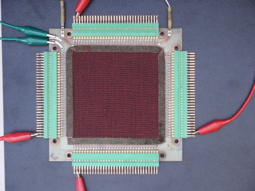
Organised as 64 rows by 64 columns, this Univac III core memory plane of early 60's vintage has a storage capacity of 4096 bits. I bought it on eBay, not with the intention of having it framed, but to make some sort of retro-computing demonstrator, possibly using discrete transistors. I don't know how far I'll get with this, but I've taken the first step by reading and writing a single bit.
I had no specific information about the plane to start with. My aim was to experimentally determine: half select current; sense pulse amplitude and position. The next step is to design a sense amplifier with a strobe to sample at the point of maximum signal-to-noise.
The sleeved wires at the top of the photo, terminated to the left and right of the (modern) green edge connector, are the inhibit wire. This can clearly be seen running parallel to the vertical select wires in Zoom3. The green crocodile clips are attached to the sense wire.
The output of constant current source Q1 is fed through the XY select wires by H-bridge Q2, 3, 7, 8. Trimmer VR1 sets the half select current. Typically, this varies between 150 and 500mA, depending on core size. Around 400mA seems to be about right for this plane, which has quite large cores. Conveniently, since I'm only flipping one core, the X and Y select wires are driven in series.
The driver was simulated in LTSpice to estimate rise-time. This was another unknown: too slow and I'd get a weak sense pulse; too fast and there'd be excessive ringing. The prediction was 100ns, but I had no idea if that was OK. According to James R Jones' excellent article [1,2] it "should be about half the core design time for a 1 peak to occur" which turned out to be 400ns, so I was a bit fast.
I found it necessary to switch the current source as well as the output transistors, otherwise the rising edge massively overshot the programmed current, presumably due to saturation of Q1.
Noise and ringing were big problems with core memory. The sense wire is threaded to minimise noise pickup, but every current transition on the select wires produces some output. A short time after the initial glitch, we also get a longer, slower pulse whenever a core flips:
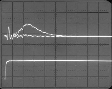 VERT 50 mV HORZ 200 ns |
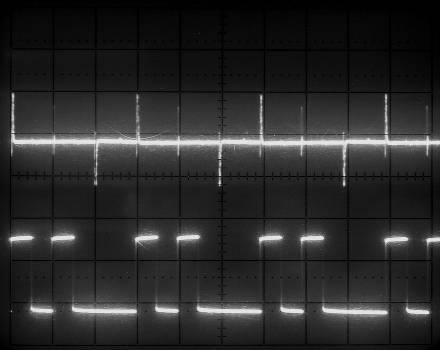 VERT 50 mV HORZ 20 µs |
The lower trace is the read-enable signal. The upper trace shows core reversals coincident with write pulses, and the first read. Sense amplitude reaches a maximum of 50mV after about 400ns. Notice how the wiggles on the "1" and "0" paths exactly coincide. By triggering a monostable on the select transition, we can generate a read-strobe signal, and clock the data into a flip-flop at the point of maximum noise immunity.
Device g16v8ms ; pin 1 = CLK; pin 11 = !OE; pin [13,14,16] = [State0..2]; pin 12 = Enable; pin 15 = Read; pin 17 = Write; sequence [State0..2] { present 0 next 1; present 1 next 2 out Enable.d out Write.d; present 2 next 3; present 3 next 4 out Enable.d out Read.d; present 4 next 5; present 5 next 0 out Enable.d out Read.d; } |
WANG 700 Schematics Includes core memory driver circuitry
Elliott 803 Computer How Elliott's used ferrite cores as logic elements
| Copyright © Andrew Holme, 2005. |


|