Go To Table of Contents
|
BRL 1961, WESTINGHOUSE AIRBORNE, start page 1012
|
WESTINGHOUSE AIRBORNE
Westinghouse Airborne Digital Data Processor
MANUFACTURER
Air Arm Division
Westinghouse Electric Corporation
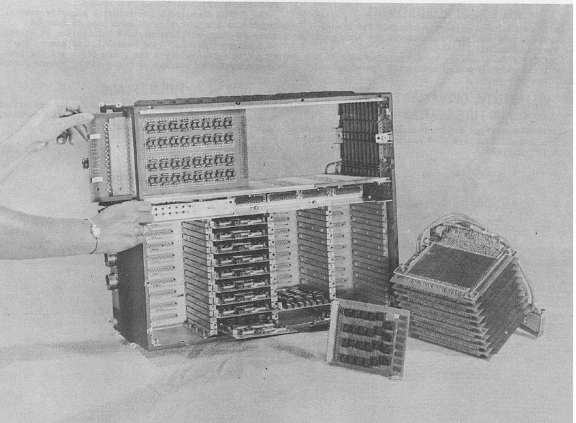
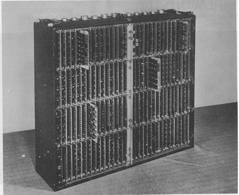
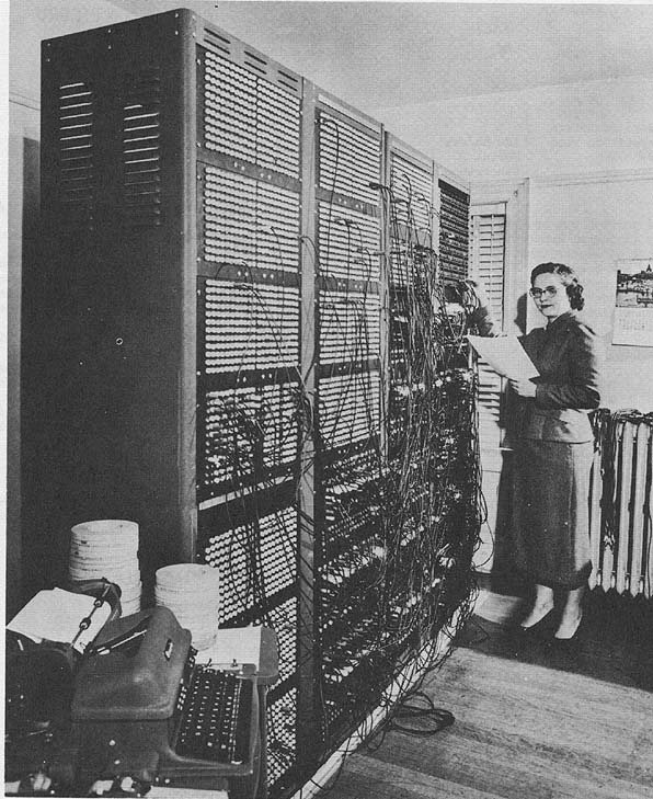
Operand Memory Photo by Westinghouse Electric Corporation
APPLICATIONS
System is used to process radar data, generate
synthetic displays, and direct antenna. The computer
is used also to conduct built in system tests, per-
form diagnostic tests of the Data Processor itself
and generate calibration displays.
The Westinghouse Airborne Digital Data Processor
is a problem oriented general purpose digital compu-
ter developed by Westinghouse for the Bureau of
Aeronautics. Problem orientation of the Data Pro-
cessor stems from its function as a sub-system of a
radar processing system with multiple target hand-
ling capability.
PROGRAMMING AND NUMERICAL SYSTEM
Internal number system Binary
Binary digits/word 24
Binary digits/instruction 21
Instructions/word One (two instruction
words per memory line)
Instructions decoded 4096
Arithmetic system Fixed point
Instruction type One address
Number range - 1 < n < +1
Instruction word format
+--+--+--+--+--+--+--+--+--+--+--+--+--+--+--+--+--+--+--+--+--+
|21|20|19|18|17|16|15|14|13|12|11|10| 9| 8| 7| 6| 5| 4| 3| 2| 1|
+--+--+--+--+--+--+--+--+--+--+--+--+--+--+--+--+--+--+--+--+--+
| Inst. Field |Index| Address Field |
+--------------+-----+-----------------------------------------+
Field Designation for Instruction Word
|
BRL 1961, WESTINGHOUSE AIRBORNE, start page 1013
|
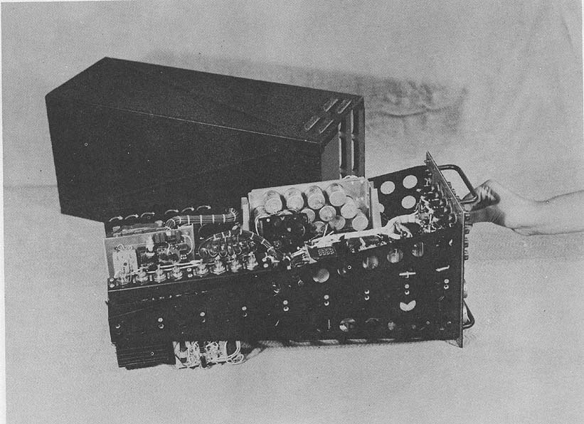
Power Supply Photo by Westinghouse Electric Corporation
Registers and B-boxes
Accumulator X-Register
Q-Register 3 Index Registers
M-Register IS-Register
Stored Data Processing program consists of many sub-
routines.
Data-constant words are expressed in a complement form.
Operand words are stored two words per operand memory line.
Programmer has choice of left or right word, left or right half of
left word, or left or right half of right word. These choices
provide for maximum use of data locations.
ARITHMETIC UNIT
Incl. Stor. Access Exclud. Stor. Access
Microsec Microsec
Add 3 1.4
Mult 20 20
Div 40 40
Construction (Arithmetic unit only)
Transistors 2,600
Arithmetic mode Parallel
Timing Synchronous
Operation Sequential
STORAGE
No. of Access
Media No. of Words Dig/Words Microsec
Magnetic Core 4096 Inst Words 21 0.2
Magnetic Core 1024 Oper Words 24 0.8
Magnetic Tape
No. of units that can be connected 1 Unit
No. of characters/linear inch200 Chars/inch
Channels or tracks on the tape 7 Tracks/tape
Tape speed 75 Inches/sec
Start time 3 Millisec
Stop time 3 Millisec
Physical properties of tape
Width 0.5 Inches
Length of reel 2,400 Feet
Composition Mylar
Selected data recorded on tape compatible with IBM 727 tape
unit.
Provides checking feature for processed data.
|
BRL 1961, WESTINGHOUSE AIRBORNE, start page 1014
|
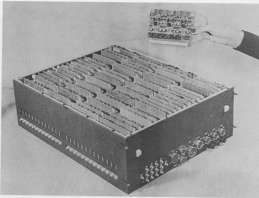
Input Unit Photo by Westinghouse Electric Corporation
INPUT
Media Speed
Hi-speed Block 3 microsec/data word
Transfer
Voltage to Digital 75 microsec 0.1% Resolution
Sense Inputs 3 microsec
Special input unit designed to receive information from radar
and present it to Data Processing units.
OUTPUT
Media Speed
Hi-speed Block Transfer 3 microsec/data word
Digital to D-C Voltages 15 microsec read-out
0.1% Resolution
Digital to A-C Voltages 9 microsec read-out
0.2% Resolution
Special output unit designed to receive data from the
arithmetic/control unit, decode data, output to the antenna
director, display of tracked targets on console, and output to tape
unit.
CIRCUIT ELEMENTS OF ENTIRE SYSTEM
Type Quantity
Diodes 15,985
Transistors 7,597
Magnetic Cores 113,600
Gating systems operate on DC levels with approximately 10
millimicroseconds of delay per stage.
Multi-aperture core Instruction Memory with
NonDestructive Read-out.
CHECKING FEATURES
Internally Programmed Self Test
Arithmetic/control monitor capable of testing and holding
the contents of a particular register at any
prescribed time.
Readily accessible test points permit rapid trouble shooting
without removing cards or units from mounting structure.
|
BRL 1961, WESTINGHOUSE AIRBORNE, start page 1015
|
Arithmetic/Control Unit Photo by Westinghouse Electric Corporation
POWER, SPACE, WEIGHT,AND SITE. PREPARATION
Power, computer and power 1.8 Kw 1.8 KVA 1.0 pf
Volume, computer 6.5 cu ft
Area, computerDependent on mounting application
Weight, computer 250 lbs
Data Processor is designed for airborne use.
Mounting structure depends on space available. Cool-
ing required is a blower with a capacity of 200 cfm
at max amb temperature 38oC min air density .052
lbs/ft2. System requires 115v, 400 cycle, 3-phase,
600 watts/phase, or 28v D. C. 3 wire.
PRODUCTION RECORD
Number produced to date 2
Number in current operation 2
Current operating models are prototype.
RELIABILITY. OPERATING EXPERIENCE,
AND TIME AVAILABILITY
System features and construction techniques utilized by the manufacturer to
insure required reliability include selected standard parts proven long life
items with extensive life testing operations, electrical components derated to
operate at 200 of nominal voltages and power ratings, and circuits designed
to accomodate wide swings in component parameters.
ADDITIONAL FEATURES AND REMARKS
Outstanding features include Hi speed (300,000 operations/sec) in a
ruggedized, small package, high reliability, and general purpose command
repertoire with three Index Registers.
Unique system advantages include Non-Destructive Instruction Store
with 1 microsecond memory cycle time, and split word storage, allowing
programmer a choice of a 24 bit whole word or a 12 bit half word.
INSTALLATIONS
Westinghouse Electric Corporation
Air Arm Division
Avionics Systems Section (454)
Box 746
Baltimore 3, Maryland
|
BRL 1961, WHIRLWIND II, start page 1016
|
WHIRLWIND II
The Whirlwind Computer
MANUFACTURER
Massachusetts Institute of Technology Digital
Computer Laboratory
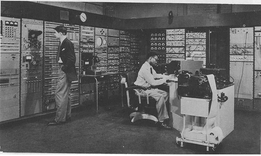
Photo by Massachusetts Institute of Technology
APPLICATIONS
Manufacturer Scientific and engineering computation. The research
reported in this computing system description was sponsored by the Office of
Naval Research. Air defense experiments leading to development of the SAGE
System. The Whirlwind I Computer was declared excess to the needs of the M. I.
T. Lincoln Laboratory in the spring of 1959. Subsequently, the computer was
leased by the Office of Naval Research to the Wolf Research and Development
Corporation, Boston, Mass. The Wolf Research and Development Corporation
then undertook the disconnecting and moving of the computer from the M. I. T.
Barta Building. This move which commenced about 1 January 1960 was
successfully completed by 1 May 1960. The computer is presently stored in a
Navy warehouse and it is planned to move the machine and make it operational
at a new site during early 1961.
PROGRAMMING AND NUMERICAL SYSTEM
Internal number system Binary
Binary digits/word 16
Binary digits/instruction 16
Instructions/word 1
Instructions decoded 32
Instructions used 29
Arithmetic system Fixed point
Instruction type One address
Number range 2-15 - 1 to 1 - 2-15
Instruction word format
+--------------+--------------------------------+
| Operation | Address |
+--+--+--+--+--+--+--+--+--+--+--+--+--+--+--+--+
| 0| | | | 4| 5| | | | | | | | | |15|
+--+--+--+--+--+--+--+--+--+--+--+--+--+--+--+--+
The basic operation code has been supplemented by a comprehensive system
of service routines, providing for direct read-in of Flexowriter-coded perforated
paper tapes, the logging of each problem on film and paper tape for subsequent
processing, assembly during read-in of a suitable set of instructions including
interpretive programmed-arithmetic (optional floating
|
BRL 1961, WHIRLWIND II, start page 1017
|
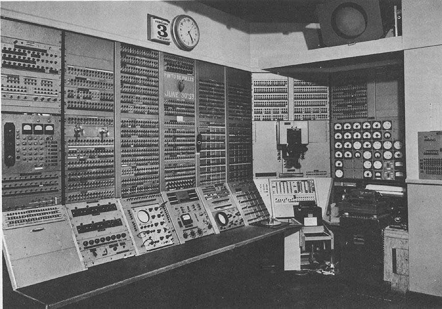
Photo by Wolf Research & Development Corporation
point), up to several hundred cycle counters (B-boxes), output
routines, error detection, and automatic post mortems.
Routines are normally coded with mnemonic operations,
symbolic addresses, relative addresses, program preset parameters,
special psuedo-codes, and special control words.
The service routines are stored on magnetic tape and are
selected automatically during read-in.
ARITHMETIC UNIT
Incl Stor Access Exclud Stor Access
Microsec Microsec
Add 22 8
Mult 34-41 23.5
Div 71 57
Construction (Arithmetic unit only)
Type Quantity
6145 517
7AK7 441
6SN7 96
3E29 14
6Y6 51
Basic pulse repetition rate 1 Megacycle/sec
Arithmetic mode Parallel
Timing Synchronous
Operation Concurrent
STORAGE
Access
Media Microsec
Magnetic Core 6,144 7
Two Magnetic Drums 36,848 8,300
Five Magnetic Tapes 125,000/tape
Toggle Switch 32 1
Flip-flop 5 1
A word consists of 16 digits plus a parity digit.
Read-rewrite time is 7 microseconds. Drum access
time is average value.
Magnetic Tape
No. of units that can be connected 4 Units
No. of words/linear inch of tape 13 Words/inch
Channels or tracks on the tape 6 Tracks/tape
Blank tape separating each record 0.6 Inches
Tape speed 30 Inches/sec
Transfer rate 390 Words/sec
Start time 6.0 Millisec
Stop time 6.5 Millisec
Average time for experienced operator
to change reel of tape 60 Seconds
Physical properties of tape
Width 1/2 Inches
Length of reel 800 Feet
Composition Acetate
Magnetic core storage consists of two banks of 1024 words
each and one bank of 4096 words. These are divided into 6 fields
of 1024 words, any two of which
|
BRL 1961, WHIRLWIND II, start page 1018
|
may be used at a given time. A change fields instruction permits
selection of the two fields to be used. A word consists of 16 digits
plus a parity digit. Read-rewrite time is seven microseconds.
Magnetic drum storage consists of an auxiliary drum containing
12 groups each consisting of 2048 words plus six groups of 2048
words each contained on a buffer drum. The buffer drum contains
four other groups which are used for input-output buffering of
digital data.
A total of five magnetic tape units is available, of these a
maximum of four may be connected to the computer at any
one time and up to three may be connected to the associated
delayed (off-line) printout system.
INPUT
Media Speed
Paper Tape (Ferranti) 200 lines/sec
Paper Tape (Flexowriter) 14 lines/sec
Magnetic Tape 30 in/sec
Light Guns Manual
Paper Tape (Teletype) 60 words/min
Switches Manual
Digital Data Input 1,300 points/sec
Real Time Clock 60 pulses/sec
OUTPUT
Media Speed
Magnetic Tape 188 char/sec
Oscilloscope-camera 200 char/sec
Paper Tape (Flexowriter) 10 char/sec
Oscilloscope-Camera 2 frames/sec
Oscilloscope-Display 6,000 points/sec
Printed Page (Flexowriter) 10 char/sec
Paper Tape (Teletype) 60 words/min
Printer (Teletype) 60 words/min
Digital Data Outputs 1,300 pulses/sec
Audible Alarm-Lights 4 words/sec
The oscilloscope displays vectors at the rate of 6,000
vectors/sec and characters at the rate of 3,000 char/sec. An IBM
523, modified, is used for reading and punching. Magnetic tape
may be used for delayed Flexowriter output (off-line).
CIRCUIT ELEMENTS OF ENTIRE SYSTEM
Type Quantity
Tubes 14,500
7AK7 6,145
6145 5,665
40 Types
Diodes 14,000
Transistors None
Magnetic Cores 104,448
Used in core memory only.
CHECKING FEATURES
Arithmetic element checks, parity checks of core memory
and magnetic drums, and information transfer checks.
Marginal checking is done one hour daily to determine if any
computer circuits have deteriorated during the past 24 hours.
POWER, SPACE, WEIGHT, AND SITE. PREPARATION
Power, computer 200 KVA
Power, air conditioner 150 KVA
Volume, computer 4,400 cu ft
Volume, input-output 2,100 cu ft
Volume, air conditioner 4,200 cu ft
Area, computer 450 sq ft
Area, input-output 210 sq ft
Area, sir conditioner 525 sq ft
Room size, computer 30 ft x 70 ft
Room size, input-output 25 ft x 40 ft
Room size, air conditioner 30 ft x 50 ft
Floor loading 12 lbs/sq ft
60 lbs concen max
Capacity, air conditioner 110 Tons
Weight, computer 37,000 lbs
Weight, air conditioner 16,000 lbs
PRODUCTION RECORD
Number produced to date 1
PERSONNEL REQUIREMENTS
One 8-Hour Two 8-Hour Three 8-Hour
Shift Shifts Shifts
Supervisors 1 1 1
Librarians 1 1 1
Operators 1 2 3
Engineers 1 1 1
Technicians 2 4 6
In-Output Oper 2 2 2
Tape Handlers 2 2 2
RELIABILITY, OPERATING EXPERIENCE,
AND TIME AVAILABILITY
Average error-free running period 19.4 Hours
Good time 3,172.3 Hours
Attempted to run time 3,237.9 Hours
Operating ratio (Good/Attempted to run time) 0.98
Figures based on period 15 May 56 to 24 Sep 56
Passed Customer Acceptance Test 1950
ADDITIONAL FEATURES AND REMARKS
Outstanding features are the display system including twenty-
five 16" display scopes, 19 5" display scopes, 13 light guns,
manual intervention switches and audible alarms. Digital data
inputs and outputs via telephone lines, teletype input and output
and real time clock.
INSTALLATIONS
Digital Computer Laboratory
Massachusetts Institute of Technology
Cambridge 39, Massachusetts
|
BRL 1961, WISC, start page 1020
|
WISC
Wisconsin Integrally Synchronized Computer
MANUFACTURER
University of Wisconsin
Department of Electrical Engineering
Computing Laboratory
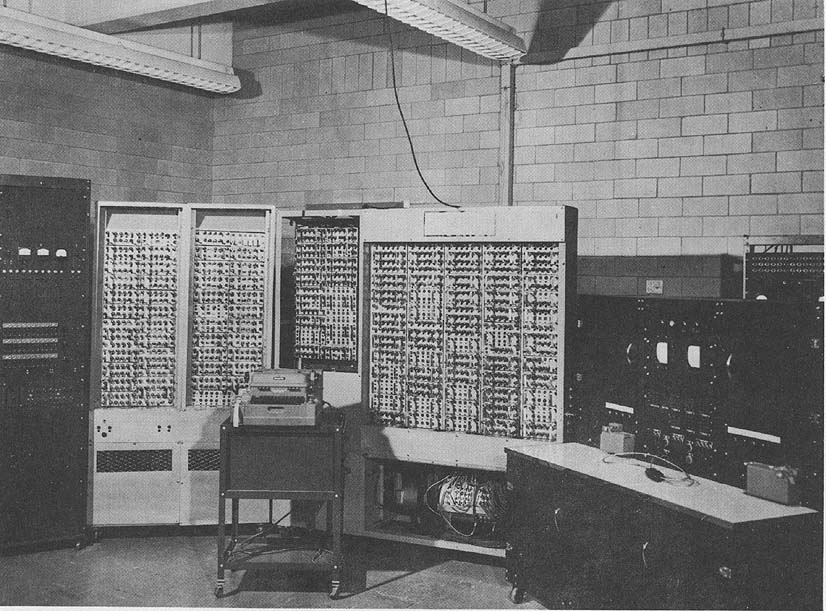
Photo by the University of Wisconsin
APPLICATIONS
General purpose scientific and engineering computation,
engineering experimentation and training.
PROGRAMMING AND NUMERICAL SYSTEM
Internal number system Binary
Binary digits/word 50
Binary digits/instruction 50
Instructions word 1
Instructions decoded 16
Instructions used 16
Arithmetic system Floating point
Instruction type Three address
Number range 40 binary digits times 2+-255
Instruction word format
+---------+-------+---------+---------+----------+
| 10 | 4 | 12 | 12 | 12 |
+---------+-------+---------+---------+----------+
| X | T | A | B | C |
| SPECIAL | TYPE | ADDRESS | ADDRESS | ADDRESS |
+---------+-------+---------+---------+----------+
| 50 - 41 | 40-37 | 36 - 25 | 24 - 13 | 12 - 1 |
+---------+-------+---------+---------+----------+
1 bit (#49) used to select fixed point operation, breakpoint operation, etc. 6
bits (#41-46) used (along with 12 bits) to allow completely general Extract
operation: Extract any number of bits from any stored word, shift right or left
any number of places, insert into arty other stored word.
|
BRL 1961, WISC, start page 1021
|
ARITHMETIC UNIT
Incl. Stor. Access-
Microsec
Add 16,700
Mult 16,700
Div 16,700
Construction (Arithmetic unit only
Type Quantity
Tubes
6211 400
5844 l00
6AW8 4
6CM6 6
Diodes
1N38 200
Rapid access word registers 7
Basic pulse repetition rate 100 Kc/sec
Arithmetic mode Serial
Timing Synchronous
Operation Sequential
Concurrent
Operations are carried out on four instructions simultaneously (Integral
Synchronization) resulting in efficient use of access time. The four
concurrent operations are read order N, locate two operands called for by
order N-1, perform arithmetic of order N-2, and deliver result of order N-3.
Floating point makes efficient use of otherwise long addition time.
STORAGE
No. of No. of Access
Media Words Digits Microsec
Magnetic Drum 1,024 51,200 0 - 16,700
Magnetic Drum 4 550
Magnetic Drum 3 440
INPUT
Media Speed
Punched Paper Tape 10 sexadec char/sec
Flexowriter Keyboard Manual
OUTPUT
Media Speed
Punched Paper Tape 10 sexadec char/sec
Flexowriter Typewriter 10 sexadec char/sec
Oscilloscope Monitor
CIRCUIT ELEMENTS OF ENTIRE SYSTEM
Type Quantity
Tubes
5844 650
6211 650
6AQ5 - 6CM6 100
6AW8 14
6AG5 32
Diodes
1N38 400
1N1128 3
1N1128R 3
6AQ6 being replaced by 6CM6
CHECKING FEATURES
Manually operated marginal checking voltages Set of diagnostic
routines
POWER, SPACE, WEIGHT, AND SITE PREPARATION
Power, computer 10.5 Kw
Power, air conditioner 7.5 Kw
Area, computer 40 sq ft
Area, air conditioner 15 sq ft
Capacity, air conditioner 7.5 Tons
PRODUCTION RECORD
Produced 1
Operating 1
PERSONNEL REQUIREMENTS
One 8-Hour Shift
Engineers 1
Technicians Students
ADDITIONAL FEATURES AND REMARKS
Extract instruction and floating point controls.
Remote control.
Digits in instructions corresponding to the sign of significant digits in
numbers are not used in any instruction. Extract instruction is the only
instruction which makes use of digits corresponding to exponent in
numerical data.
System is financed by the Wisconsin Alumni Research Foundation and the
University of Wisconsin, College of Engineering, Department of Electrical
Engineering.
Design was governed largely by striving for simplicity of operation.
Outstanding features include integral synchronization, general extract, fixed
or floating point operation and a 50 bit word length.
FUTURE PLANS
Indirect addressing with automatic modification has been designed
and a photoelectric reader and high speed punch have been acquired.
INSTALLATIONS
Computing Laboratory
Department of Electrical Engineering
College of Engineering
University of Wisconsin
Madison 6, Wisconsin
�
|
BRL 1961, WRU SEARCHING SELECTOR, start page 1022
|
WRU SEARCHING SELECTOR
Western Reserve University Searching Selector
MANUFACTURER
Western Reserve University
Photo by Western Reserve University
APPLICATIONS
Located at 10831 Magnolia Road, Cleveland 6, Ohio, the system is used for
the scanning of encoded abstracts of scientific publications for literature
searching purposes. Applied to literature projects of American Society for
Metals, American Diabetes Association, and Communicable Disease Center
(Atlanta, Ga.).
Media STORAGE
Paper Tape Library
Relays
The paper tape library is scanned at Flexowriter speeds.
�
|
BRL 1961, WRU SEARCHING SELECTOR, start page 1023
|
INPUT
Medium Speed
Paper Tape 10 char/sec
OUTPUT
Medium Speed
Typed Page 10 char/sec
Paper Tape 10 char/sec
PERSONNEL REQUIREMENTS
One 8-Hour Shift Two 8-Hour Shifts
Used Recomm Used Recomm
Analysts 1 1 1 1
Programmers 1 1 1 1
Operators 1 1 2 2
RELIABILITY, OPERATING EXPERIENCE,
AND TIME AVAILABILITY
Good time 60 Hours/Week (Average)
Attempted to run time 70 Hours/Week (Average)
Operating ratio (Good/Attempted to run time) 0.86
Above figures based on period 1 Jan 60 to 1 May 60
Time is available for rent to qualified outside organ-
izations.
ADDITIONAL FEATURES AND REMARKS
The starting point for designing this equipment was the realization that
documentation systems are called upon to meet a wide variety of information
requirements. These range from narrowly defined specific inquiries to
comprehensive correlations. More detailed analysis revealed that any given
requirement almost without exception invclves a combination of several
concepts. Both subject indexing, as ordinarily practiced, and the pigeon-hole
type of classification systems make use of preestablished concept combinations
insofar as such combinations are used at all. Hand-sorted punched cards and
various mechanized systems have demonstrated during the past ten years that
highly advantageous benefits may be realized by defining searching and
selecting operations in terms of concept combinations not established or
anticipated at the time of analyzing the subject contents of documents.
The Western Reserve Searching Selector permits an exceptionally wide range
of concepts to be used in defining and conducting searching operations. Thus, the
scope of a search may be defined not only in terms of specific substances, devices,
attributes, processes, conditions, organisms, persons, locations, etc., but also in
terms of generic concepts and their relationships to specific terms. Furthermore,
observational relationships, for example the roles in a given experiment or
situation of various substances, devices, etc, taken either specifically or
generically, may also be designed as points of reference in defining searches.
This wide range of possibilities is accomplished by the ability of the Western
Reserve Searching Selector to detect combinations of symbols and combinations
of combinations at a multiplicity of levels. At each level, combinations may be
defined in terms of logical product, logical sum, logical difference or derived
complex logical relationships. The different combinational levels may be thought
of as analogous to the combining of letters to construct sentences, sentences to
construct paragraphs, etc. The machine is able automatically to detect the start
and end of each organized symbolic unit analogous to word, phase, sentence,
or paragraph.
� This use of analogy, though illuminating, must not be regarded as definitive.
Actually, to avoid the complexity of phrasing and sentence structure
encountered in natural language, well-defined rules for indicating relationship
of a syntactical nature have been worked out. Application of these rules results
in the expressing of the subject content of a given document in the form of a
telegraphic-style abstract with syntactical relationships rendered explicit by
carefully defined role indicator. Encoding the terminology in such abstracts
explicitly indicates the relationship of each term to concepts of generic scope.
Prior to conducting a search, an information requirement is analyzed in terms
of appropriate specific and generic terms, role indicators and logically defined
relationships between them. The information requirement is thus analyzed on
the same basis as is used to record the information contents of documents in the
form of encoded abstracts. The searching step as performed by the Searching
Selector consists of a series of logically defined matching operations involving
the common set of terms used for analyzing the information requirement and the
information contents of documents:
The Searching Selector has been designed so that ten searches may be
conducted simultaneously. Such searches may be interrelated as to scope or
completely independent.
FUTURE PLANS
The system has been replaced during 1960 with the GE 250 computing
system.
INSTALLATIONS
Center for Documentation and Communication Research Western Research
University Cleveland 6, Ohio
This use of analogy, though illuminating, must not be regarded as definitive.
Actually, to avoid the complexity of phrasing and sentence structure
encountered in natural language, well-defined rules for indicating relationship
of a syntactical nature have been worked out. Application of these rules results
in the expressing of the subject content of a given document in the form of a
telegraphic-style abstract with syntactical relationships rendered explicit by
carefully defined role indicator. Encoding the terminology in such abstracts
explicitly indicates the relationship of each term to concepts of generic scope.
Prior to conducting a search, an information requirement is analyzed in terms
of appropriate specific and generic terms, role indicators and logically defined
relationships between them. The information requirement is thus analyzed on
the same basis as is used to record the information contents of documents in the
form of encoded abstracts. The searching step as performed by the Searching
Selector consists of a series of logically defined matching operations involving
the common set of terms used for analyzing the information requirement and the
information contents of documents:
The Searching Selector has been designed so that ten searches may be
conducted simultaneously. Such searches may be interrelated as to scope or
completely independent.
FUTURE PLANS
The system has been replaced during 1960 with the GE 250 computing
system.
INSTALLATIONS
Center for Documentation and Communication Research Western Research
University Cleveland 6, Ohio
Go To Table of Contents