Go To Table of Contents
|
BRL 1961, SCRIBE, start page 0846
|
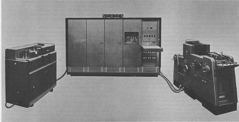
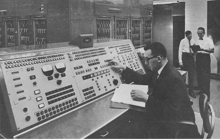
SCRIBE
Scoring and Data Transcription Computer
MANUFACTURER
United Aircraft Corporation
Norden Division
Photo by Educational Testing Service
APPLICATIONS
Manufacturer
System is used for special purpose data processing and off-line
scoring and transcription, with general applications to
topologically equivalent systems. Educational Testing Service
Located at Princeton, New Jersey, the SCRIBE consists of a
paper handler and mark-sensing unit, a processing unit and a card
punch. It is designed primarily for the processing of test answer
sheets. As a data processor and transcriber, it processes up to
2,240 pencil marks on one side of one 8 1/2" x 11" sheet of
paper onto one punched card at the rate of 100 sheets per
minute.
PROGRAMMING AND NUMERICAL SYSTEM
Manufacturer
Internal number system Binary Coded Decimal
Decimal digits/word Variable
Binary digits/instruction 5
Instructions per word Variable 1 to 3
Instructions decoded 15
A single bit adder is used.
Instruction type One address
Number range 0 - 999
Instruction word format is variable.
A wired program interpreting core memory is used. The equipment
is a special purpose data processor used mainly for the scoring and
transcription of answer sheets. It can be used for other
topologically equivalent documents. It is programmed by scanning an array
sheet which is marked in accordance with the identification
instructions and their addresses. A drum memory with 24 answer
keys is used for automatically scoring as many as 6 different
keys indicated on an answer sheet.
ARITHMETIC UNIT
Manufacturer
Construction (Arithmatic unit only)
Transistors and diodes are used in a single bit
adder.
Arithmetic mode Serial
Timing Synchronous
Operation Sequential
STORAGE
Manufacturer
No. of No. of Access
Media Words Bits Microsec
Core 600 17 14
Drum 784 40 17,000
The drum memory also contains two 480 bit recirculating
registers for output buffering to card pinch.
�
|
BRL 1961, SCRIBE, start page 0847
|
INPUT
Manufacturer
Medium Speed
8 1 /2 x 11 inch Sheet 100 sheets/min
(2240 marking positions)
The sheet is arranged into 40 positions per row and a me-
ydnnn of 56 rows. The row arrangement is 8 groups of
positions.
OUTPUT
Manufacturer
Medium Speed
Punched card (80 column) 100 cards/min
Parallel card punch speed synchronous with input.
CIRCUIT ELEMENTS OF ENTIRE SYSTEM
Manufacturer
Type Quantity
Diodes
1N700 Approximately 5, 000
et al
Transistors
2N317
2N388
2N404
2NN426
and others
Total Approximately 3,500
Magnetic Cores 10,800
There are a few vacuum tubes (L10) in the system for voltage
reference plus the photomultiplier tubes used for sensing.
CHECKING FEATURES
Manufacturer Checking features include many built
in routines plus parity check on magnetic core memory.
POWER. SPACE. WEIGHT. AND SITE. PREPARATION
Manufacturer
KVA, System 3 KVA
Volume, system 250 cu ft
Area, System 50 sq ft
Floor loading 86 lbs/sq ft
Weight, System 4,300 lbs
Air conditioned at 60o - 95oF
Relative humidity at 20% - 60%.
208 v, 3 phase, 60 cps
PERSONNEL REQUIREMENTS
Manufacturer
One 8-Hour Two 8-Hour
Shift Shifts
Operators 1 2
Engineers 1 1
Technicians 1 2
In-Output Oper 1 2
Training made available by the manufacturer to the user
includes training to suit users requirements.
ADDITIONAL FEATURES AND REMARKS
Manufacturer
Provides mark sensing capabilities of most intense mark in a
group plus ability to provide for variations in background level.
Includes printing facility for identifying sheets in alternate stack.
System has a capability of scoring mixed answer sheets of
different tests.
Educational Testing Service
Outstanding features include sensing of marks by reflected
light, extensive automatic checking, and stored-program
processing.
Unique system advantages include the ability to use any of 24
distinct scoring keys during one scoring run, the ability to process
positionally coded information, and the ability to shunt certain
sheets aside for separate processing.
INSTALLATIONS
Educational Testing Service
20 Nassau Street
Princeton, Hew Jersey
�
|
BRL 1961, SEAC, start page 0848
|
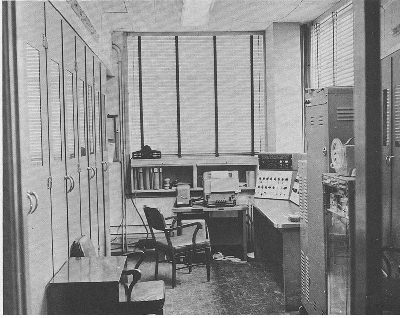
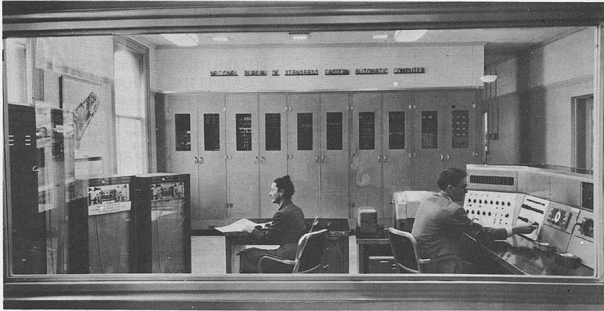
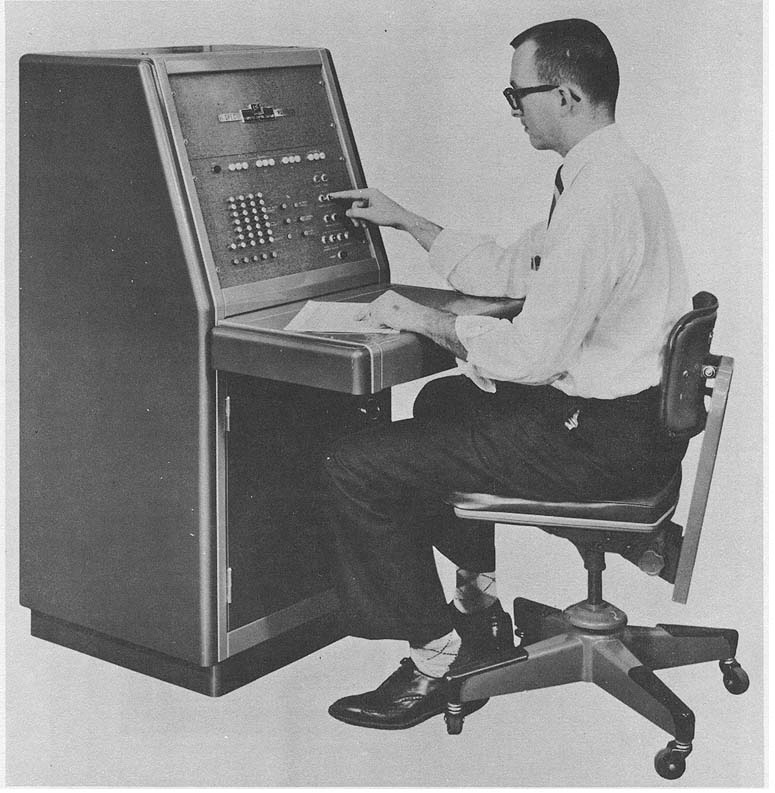
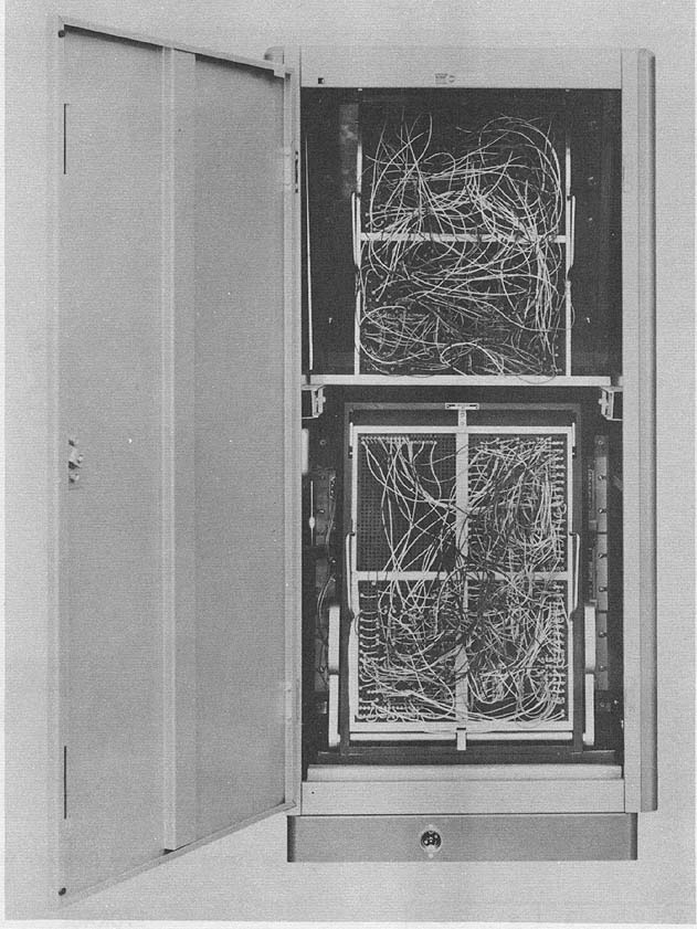
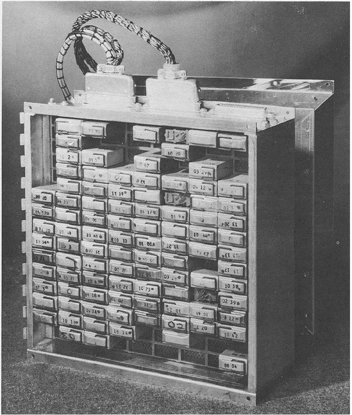
SEAC
Standards Electronic Automatic Computer
General Purpose Scientific Calculator
MANUFACTURER
National Bureau of Standards U. S.
Department of Commerce
Picture by National Bureau of Standards
APPLICATIONS
General data processing, scientific calculation and engineering
development. Man-machine systems studies in conjunction with
analog computer.
PROGRAMMING AND NUMERICAL SYSTEM
Internal number system Binary
Binary digits per word 44 plus sign
Binary digits per instruction 45
Instructions per word 1
Instructions decoded 16
Instructions used 16 + 2 optional (switch)
Arithmetic system Fixed point
Instruction type Three or four address (switch)
Number range - (4 - 2-42) to + (4 - 2-42)
Instruction word format
+-------+---------+---------+---------+---------+--------+-------+
| 4 Ad- | 10 bits | 10 bits | 10 bits | 10 bits | 4 bits | 1 bit |
| dress | a | B | y | & | opera- | sign |
| | | | | | tion | |
+-------+---------+---------+---------+---------+--------+-------+
+-------+---------+---------+---------+---------+--------+-------+
| 3 Ad- | 12 bits | 12 bits | 12 bits | 4 bits | 4 bits | 1 bit |
| dress | a | B | y | counters| opera- | sign |
| | | | | | tion | |
+-------+---------+---------+---------+---------+--------+-------+
In 3 address operation instruction sequencing is done by 2
counters which are independently sequenced by bits in the
instruction. Relative programming can thus be accomplished.�
|
BRL 1961, SEAC, start page 0849
|
Picture by National Bureau of Standards
ARITHMETIC UNIT
Incl. Stor. Access Exclud. Stor. Access
Microsec. Microsec.
Add time 192 - 1,540 48
Mult time 2,300 - 3,650 2,112
Div time 2,300 - 3,650 2,112
Construction 1200 Germanium diodes, 80 delay lines, 60 pulse
transformers, 61 vacuum tubes.
Rapid access word registers 3
Basic pulse repetition rate 1 Megacycle/sec
Arithmetic mode Serial
Timing Synchronous
Operation Sequential
Operation time varies with memory being used. Acoustic and
electrostatic memory may be used together in computer.
STORAGE
Microsec
Media Words Digits Access
Acoustic (Mercury) 1,024 46,080 216 (avg)
Electrostatic (CRT) 1,024 46,080 12
Magnetic Tape 24,000 52 x 24 x 103 bits/unit
No. of units that can be connected 5 Units
No. of chars per linear inch 260 Chars/inch
Channels or tracks on the tape 7 Tracks/tape
Blank tape separating each record 0.75 Inches
Tape speed 37.5 Inches/sec
Transfer rate 104 Chars/sec
Start time 0.5 Millisec
Stop time 0.5 Millisec
Physical properties of tape
Width 0.5 Inches
Length of reel 3600 Feet
Composition Mylar - 1 Mil
Multi-channel tape system is under construction.
INPUT
Media Speed
Keyboard (Flexowriter) Manual (Max 10 char/sec)
Paper Tape (Flexowriter) 10 char/sec
Paper Tape (Potter) 150/600 char/sec(Photoelectric)
Magnetic Wire (Pierce) 65 words/sec (New unit)
Magnetic Tape 135 words/sec (Single Channel)
Magnetic Tape 4,500 words/sec (Multichannel)
Punched Card 330 char/sec
OUTPUT
Media Speed
Printer (Flexowriter) 10 char/sec
Paper Tape (Flexowriter) 10 char/sec
Paper Tape Teletype) 58 char/sec
Paper Tape (Soroban) 240 char/sec
Magnetic Wire (Pierce) 65 words/sec
Magnetic Tape 135 words/sec
Magnetic Tape 4,500 words/sec
Input-output word lengths are single word, 8 words, or variable
block up to capacity of memory with single instruction.
�
|
BRL 1961, SEAC, start page 0850
|
CIRCUIT ELEMENTS OF ENTIRE SYSTEM
Type Quantity
Tubes
6AN5 1,625
6AK5 256
Misc 400 (approx)
Approximately 45 tube types, including power
supplies, etc.
Diodes
Germanium 24,000 (apprix)
Several types
Delay lines 850 (approx)
CHECKING FEATURES
Fixed Parity check for acoustic storage. Parity check for
electrostatic storage. Optional "AUTOMONITOR" - Order by order
and breakpoint monitoring of program progress available to
operator by console switch setting. Address in memory,
instruction being performed and its result may be printed on
Flexowriter, punched paper tape, magnetic wire or tape
automatically.
POWER, SPACE, WEIGHT, AND SITE PREPARATION
Power, computer 25 KVA
Power, air conditioner 5.76 Kw 7.2 KVA 0.80 pf
Volume, computer 680 cu ft
Area, computer 85 sq ft
Volume, air conditioner 77 cu ft
Area, air conditioner 17 sq ft
Weight, computer 3,000 lbs (Central Machine)
Weight, air conditioner 1,500 lbs.
Dimensions of computer are 5 x 17 ft. Air conditioner measures
77 x 31 x 56 inches. Floor space for computer control console,
memories and auxiliaries is 1,386 sq. ft. Floor space for sir
conditioner and power supplies is 225 sq. ft.
PRODUCTION RECORD
Number produced to date 1
Number in current operation 1
PERSONNEL REQUIREMENTS
Since SEAC is being used as a research tool rather than for
computation, it is not used on a regularly scheduled basis.
Training of programmers is done internally within the user
groups. Available only to Government agencies.
RELIABILITY, OPERATING EXPERIENCE,
AND TIME AVAILABILITY
Average error-free running period 3 hours
Good time 4,877 hours
Attempted to run time 5,786 hours
Operating ratio (Good/Attempted to run) 0.83
Figures based on period 26 Aug. 55 to 14 Sep. 56
Acceptance test May 1950
The above figures are for system reliability and include the
SEAC and all its auxiliary equipments.
Basic building block is well-designed pulse repeater stage of
excellent reliability. Plug in pulse transformers, gating diodes and
electrical delay lines simplify maintenance problems. Heat
producing elements are mounted on same side of vertical
chassises in cooled airstream. All signals are ready accessible for
oscilloscope monitoring.
When computer was in operation 20 hrs/day, 7 days a week, with
4 hrs. for preeventive maintenance, high speed circuitry was
approximately 95% reliable. Overall system 85% - 95% Computer is
now 10 years old and with reduced demands and maintenance
staff this figure mast be de-rated somewhat.
ADDITIONAL FEATURES AND REMARKS
Outstanding features include a variety of auxiliary devices,
autamonitoring of program, ease of "talking" with the machine,
and two counter registers which may be used for program
sequencing and address base numbers. See DYSEAC also.
|
BRL 1961, SEAC, start page 0851
|
FUTURE PLANS
Possibility exists for adding 1,o24 words of
acoustic delay line memory to be used as parallel
access memory for activating display devices. In
combination with the existing machine features this
will greatly aid continuing work in character
recognition studies.
INSTALLATIONS
Rational Bureau of Standards
U. S. Department of Commerce, Washington 25, D. C.
|
BRL 1961, SPEC, start page 0852
|
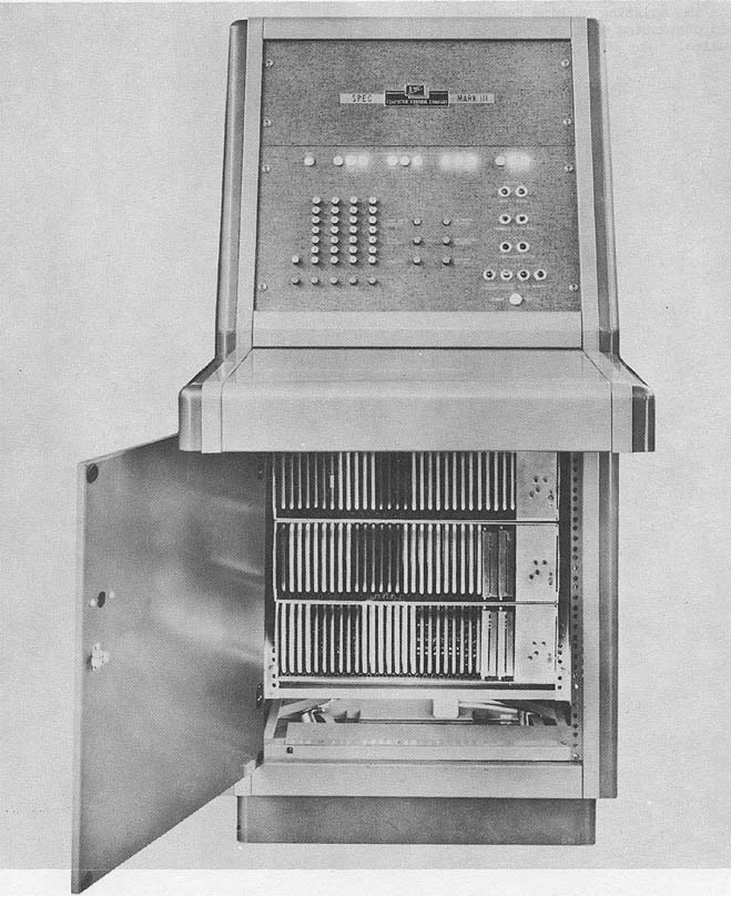
SPEC
SPEC Mark III Computing System
MANUFACTURER
Computer Control Company, Incorporated
Photo by Computer Control Company, Inc.
APPLICATIONS
System is designed and used for teaching machine
operation and basic programming techniques, teaching
logical design, general purpose computation, the
solution of differential equations, and for the rapid
implementation of special logical systems.
PROGRAMMING AND NUMERICAL SYSTEM
Internal number system Binary
Binary digits/word 13
Binary digits/instruction 13
Instructions per word One
Instructions decoded 8
Arithmetic system Fixed point
Instruction type One address
Number range - 4095 to+ 4095
|
BRL 1961, SPEC, start page 0853
|
Photo by Computer Control Company, Inc.
Instruction word format
+------+--------+---------+-----------+
| 13 | 12 11 | 10 4 | 3 1 |
+------+--------+---------+-----------+
| Sign | Unused | Address | Operation |
| | | | Code |
+------+--------+---------+-----------+
The above information applies to SPEC as a general purpose
computer. As a digital differential analyser SPEC has 20
integrators, a 21 bit word length, and is a binary, stored program
machine.
ARITHMETIC UNIT
Incl Stor Access Exclud Stor Access
Microsec Microsec
Add 221 13
Arithmetic mode Serial
Timing Synchronous
Operation Sequential
STORAGE
No. of No. of Access
Media Words Bin Digits Microsec
Magnetostrictive 128 (GPC) 13 208 (Avg)
Delay Line
Magnetostrictive 20 (DDA) 21
Delay Line
GPC - General Purpose Computer
DDA - Digital Differential Analyzer
Four 416-bit delay lines are available, in which words of
almost any length may be stored merely by making
appropriate changes in the logical wiring.
INPUT
Octal Keyboard. Speed depends on operator's skill. System input
is adaptable to punched paper tape input.
|
BRL 1961, SPEC, start page 0854
|
Rear Photo by Computer Control Company, Inc.
OUTPUT
Media Speed
Register Indicator Lights
For both GPC and DMA
Analog Output (for plotter)
MA only
Digital Output (incremental Up to 200 points/sec
for plotter
DDA only
CIRCUIT ELEMENTS OF ENTIRE SYSTEM
Type Quantity
Diodes 1,617
Transistors 279
POWER, SPACE. WEIGHT, AND SITE. PREPARATION
Power, computer 0.06 Kw
Volume, computer 19 cu ft
Area, computer 4.52 sq ft
Floor loading 68.5 lbs/sq ft
77.5 lbs concen max
Weight, computer 310 lbs
PRODUCTION RECORD
Number produced to date 1
Number in current operation 0
Number in current production 4
Number on order 4
Time required for delivery 3 months
Four are on order to Redstone Arsenal
|
BRL 1961, SPEC, start page 0855
|
COST, PRICE AND RENTAL RATES
Mark I Model $17,695.00
Mark II Model 19,195.00
Mark III Model 24,895.00
ADDITIONAL FEATURES AND REMARKS
The entire logical wiring is on removable patchboard,
which facilitates quick change from general purpose computer
to digital differential analyzer or utilization for logical
implementation. The system allows the student or user
complete freedom in logical design study without any
possibility of equipment damage due to incorrect wiring.
The SPEC (stored program educational computer) is
available in three models:
Mark I -General purpose computer only
Mark II -Digital differential analyzer only
Mark III - General purpose computer, digital
differential analyzer, universal logic
implementer.
Only Mark III has logical wiring on patchboard and may be
converted from GPC to DDA merely by interchanging two
prewired patchboards. Other arrangements of components may
be accomplished by appropriate wiring of other patchboards.
Components of SPEC are Computer Control Company's
standard plugin digital modules.
INSTALLATIONS
Computer Control Company, Inc.
Western Division
2251 Barry Avenue
Los Angeles 64, California
Redstone Arsenal
Huntsville, Alabama
|
BRL 1961, STORED PROGRAM DDA, start page 0856
|
STORED PROGRAM DDA
Stored Program Digital Differential Analyzer
MANUFACTURER
International Business Machines Corporation
Federal Systems Division
Photo by International Business Machines Corporation,
Federal Systems Division
APPLICATIONS
Computing system is used for missile guidance and the
simulation of complex weapons systems by a realtime tie-in to
an IBM 704 E. D. P. M.
PROGRAMMING AND NUMERICAL SYSTEM
Internal number system Binary
Binary digits/word nominally 22 bits
Binary digits/instruction 4
Instructions per word 5
Instructions decoded 365 (16 basic)
Arithmetic system Fixed point
Instruction type Transfer direction - "To"
and "From"
|
BRL 1961, STORED PROGRAM DDA, start page 0857
|
Instruction word format
+--------+---+---+---+---+---------+----+----+----+----+
| "From" | | | | | | | | | |
| Word | 1 | 2 | 3 | 4 | . . . . | 19 | 20 | 21 | 22 |
+--------+---+---+---+---+---------+----+----+----+----+
| "To" | | | | | | | | | |
| Word | | | | | | | | | |
+--------+---+---+---+---+---------+----+----+----+----+
| | Instruction Word Lengths | Two Bit |
| | | Word |
| | | Control |
+--------+-----------------------------------+---------+
The organization of the computer will allow various trade-off
possibilities between number of integrators, accuracy and
solution rates. For example, a solution rate of approximately
33,000 iterations per second can be achieved in generating a
sineaosine function with an accuracy of 1 part in 215. On the
other hand, a problem requiring 300 integrations with the same
accuracy can be solved at a rate of 220 iterations per second.
Program is defined as for an IBM 704 System.
ARITHMETIC UNIT
Integration 22 Microseconds
Arithmetic mode Serial
Timing Synchronous
Operation Sequential
Nominal standard mode
Iteration Rate 623 Solutions/sec
Capacity 73 Integrators (w/22 bit words)
Bit Rate 1 megacycle
Arithmetic mode can be selected to operate in a
standard mode. Rate mode (62321 x 2N iterations/sec)
or Number Mode (21 x 2N), where 0 <= N <= 5.
STORAGE
No. of No. of Access
Medium Words Digits Microsec
Magnetostrictive 219 3,358 22
Delay Line
INPUT
Media Speed
Toggle Switches
Cards (IBM 402) 240 words/sec
I/0 Register 625 words/sec
The I/0 Register is used with Tie-in to the IBM 704 EDPM.
Automatic programming by the IBM 704 EDPM can be coded
into cards which can be loaded into the DDA via the card feed
unit.
OUTPUT
Media Speed
Pulse Motor 40 pulses/sec (bidirectional)
Neon Lights (For online checks)
I/0 Register 625 words/sec (DC Analog Computer)
Pulse Motor 240 pulses/sec (Omni-directional)
The I/0 Register is used with Tie-in to an D-C
Analog Computer to provide an analog display on an
X-Y coordinate Variplotter, and/or in a solution to
a simulation problem requiring both analog and digi-
tal computations. Neon lights are used for digital
display. Pulse motors are used as direct outputs
from the DDA computer, which, in turn, can be used
to control potentiometer settings for control of an
analog plant.
CIRCUIT ELEMENTS OF ENTIRE SYSTEM
Type Quantity
DDA System
Diodes 886 (T-16G Germanium)
Transistors 309 (Microalloy Drift Germanium)
Control Unit for 704 Tie-in
Transistors 400 MADT)
30 GE 396)
Diodes 1,133 (T16G)
Total Components(with 704 Tie-in)
DDA Computer 3,114
704 Tie-in con- 4,675
trol Unit
Control Unit for ASM application
Transistors 220 (MADT)
Diodes 504 (T166)
Circuits have been packaged for ground base military
operation or airborne applications using either germanium or
silicon transistors.
CHECKING FEATURES
Manual operation in observing results of simulated problem is
possible for performing checking operations. Checks are visual -
sine-cosine generation, problem reversal, and pre-computed
accuracy at a given time from a reference.
POWER, SPACE, WEIGHT, AND SITE. PREPARATION
Power, computer 0.029 Kw
Volume, computer 0.73 cu ft
Area, computer 0.75 sq ft
Weight, computer 30.5 lbs
PRODUCTION RECORD
Number produced to date 1
Number in current operation 1
Time required for delivery 4 months
PERSONNEL REQUIREMENTS
One 8-Hour Shift
Programmers 1/4 - 1 Technicians 1/2
RELIABILITY, OPERATING EXPERIENCE,
AND TIME AVAILABILITY
Circuit designs include, 100,000 hour reliability, noise rejection
(33% to 40% of signal), environmental tests Mil-E-S272-A and
radiation tests (integrated
flux - 3 x 10¹³ neutrons/cm2). Packaging techniques
include welded encapsulated modules, cube pack, and
printed circuit cards. The estimated Mean-Time between
Failures (EMT) is 2,855 hours.
ADDITIONAL FEATURES AND REMARKS
Outstanding features include a variable solution rate mode. Unique
system advantages include automatic 704 programming and
computer flexibility for binary or ternary increment transfer. Tie-
in to IBM 704 EDPM and D-C Analog computer will provide
problem solutions requiring both full value and incremental
techniques, and permit investigation of computer
communications.
FUTURE PLANS
Plans include an increase in speed and a reduction of circuit
costs by a factor of 3.
�
|
BRL 1961, SWAC, start page 0878
|
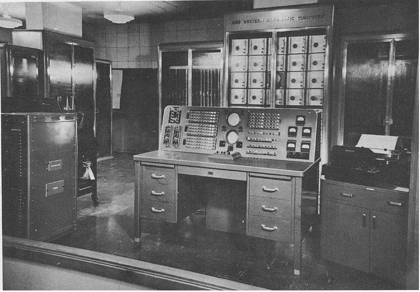
SWAC
NBS Western Automatic Computer
MANUFACTURER
National Bureau of Standards
Photo by National Bureau of Standards
APPLICATIONS
General purpose scientific computation, research in numerical
analysis computing methods. The National Bureau of Standards
Western Automatic Computer (Originally the "Zephyr", known as
SWAC). A medium-sized, high-speed computer with 256 word
electrostatic (Williams type) memory, and an 8,192 word drum
storage. The machine is described in the IRE, Proceedings,
Computer Issue, 1953. Some applications of SWAC includes the
study of discrete variable problems. The use of diffuse surface
optical model of the nucleus in the analysis of elastic scattering of
charged particles by complex nuclei. The analysis of the crystalline
structure of vitamin B12. Determination of many of the larger
prime numbers. Valuable work on semi-groups, traffic simulation,
the growth of cloud drops, counter gradient methods, queueing
theory, and on correlation and factor analysis in psychology. The
SWAC is used as a training tool and as a prototype for computer
study in courses of the UCLA curriculum. Its increased use as a data
translator is contemplated if the University acquires another high
speed computer. Some data conversion is now done on SWAG
in connection with problems to be solved on the WDPC 709
computer, operated on campus under the direction of the
Department of Business Administration.
PROGRAMMING AND NUMERICAL SYSTEM
Internal number system Binary
Binary digits/word 37 incl. sign
Binary digits/instruction 36
Instructions/word 1
Instructions decoded 13
Instructions used 13
Arithmetic system Fixed point
Instruction type Four address
Number range - (1 - 2-36) to + (1 - 2-36)
Binary point lies between sign and most significant digit.
Arithmetic is done with absolute value and sign. The fourth
address controls an optional dump and selects the auxiliary
devices.
�
|
BRL 1961, SWAC, start page 0879
|
ARITHMETIC UNIT
Incl Stor Access Exclud Stor Access
Microsec Microsec
Add 64 5.3
Mult 368 296
Div Not a logical operation
Construction 9 tubes/register
Rapid access word registers 3
Basic pulse repetition rate 125 Kc/sec
Arithmetic mode Parallel
Timing Synchronous
Operation Sequential
Auxiliary equipment asynchronous, computer halts and waits
for signal. The storage access time includes the 4th address
reference. There are 37 parallel registers in the arithmetic unit
(three input adders). System uses simultaneous carry and static
storage of the addend and the augend. Germanium diodes (semi-
conductors) for logical "and" and "or" circuitry.
STORAGE
No. of No. of Access
Media Words Digits Microsec
Electrostatic (CRT) 256 9,984 8
Magnetic Drum 8,192 311,296 17,000
The regeneration time on the electrostatic storage unit is 8
microseconds. The drum access time is given for a 64-word
block transfer. The drum transfers in blocks of 64, 32, 16 or 8
words. Average time of transfer for less than a 64 word block is
13,000 microseconds. A magnetic core memory of 512 words
has been built to replace the present 256-word electrostatic
store, and it is currently planned to attach two magnetic tape
units of 150 inch/second
read-record speed.
INPUT
Media Speed
Punched Cards (IBM) 240 cards/min
Keyboard Manual
Eleven words may be punched on each card. The key-
board is adapted for code checking. Peripheral equipment
includes IBM punched card reader, card punch,
and EAM printer, for on-line use, and a typewriter. The usual
card preparation equipment forms part of the installation.
OUTPUT
Media Speed
Punched Cards 100 cards/min
Tabulator (IBM 402) 80 lines/min
Typewriter 30 words/min
Twenty-four words per card may be punched on output. The
tabulator is a decimal output device, printing 72 characters per
line.
CIRCUIT ELEMENTS OF ENTIRE SYSTEM
Tubes 2,500
Crystal diodes 4,000
CHECKING FEATURES
Fixed
No interlocks or transfer checks are used.
Optional
Parity check on drum transfers is controlled by a
toggle switch. Breakpoints may be stored on noncommands to
halt machine when loss of control occurs.
POWER, SPACE, WEIGHT, AND SITE PREPARATION
Power, computer 30 - 35 Kw
Power, air conditioner 20 HP
Capacity, air conditioner Two 10-Ton units and a
5,000 cu ft/min fan
PRODUCTION RECORD
Number produced 1
Number operating 1
COST, PRICE AND RENTAL RATES
Approximate cost of basic system $400,000
Rental rates for additional equipment
IBM equipment $750/month
The rental charge for use of the computer and auxiliary
equipment is $40/hour. The rental rate does not apply to use of
peripheral equipment when not
connected to the computer. Such additional use is free.
PERSONNEL REQUIREMENTS
The personnel requirements for maintenance consist of one
full time supervisor, one full time principal electronics
technician, and two half-time technicians recruited from the
students.
The programming is done mostly by the users of the machine,
in "open-shop" style, but there are a programming supervisor,
one full time, and one half-time systems programmers.
RELIABILITY, OPERATING EXPERIENCE,
AND TIME AVAILABILITY
Average error-free running period 25 Minutes
Good time 796 Hours
Attempted to run time 938 Hours
Operating ratio (Good/Attempted to run time) 0.85
Figures based on period 1 Apr 56 to 30 Jun 56
Passed Customer Acceptance Test Mar 51
ADDITIONAL FEATURES AND REMARKS
The SWAC was moved during the period from September 1959
to June 1960, from quarters in a temporary building to a
permanent site in one of the Engineering buildings on campus.
While the move was underway modernization of the power
equipment was undertaken, primarily to replace obsolescent
equipment with new. The console was modernized with the addition
of a portable keyboard permitting remote operation of the
computer for instructional purposes. The drum, which had been in
operation since January 1956, was rebuilt with new bearings, and
the surface turned down. A new airconditioning plant was installed.
The computer was debugged by September 1, 1960, and has been
operating regularly since that date. Its reliability is better than
before the move, but by how much will have to be determined by
the performance records of the next few months.
INSTALLATIONS
Department of Mathematics, Numerical Analysis Research
University of California
Los Angeles 24, California
(Sponsored by:Office of Naval Research and Office of
Ordnance Research)
�
|
BRL 1961, SYLVANIA S 9400, start page 0860
|
SYLVANIA S 9400
Sylvania Model 59400 ADDS
MANUFACTURER
Sylvania Electric Products, Incorporated
APPLICATIONS
The Sylvania 9400 Data Processing System has been designed as
a general purpose computing system with built-in real time
applications ability. The computer is capable of handling the
largest of the commercial type data processing problems and is
equally at home when working on the most sophisticated
scientific problems.
PROGRAMMING AND NUMERICAL SYSTEM
Internal number system Binary
Binary digits/word 37
Binary digits/instruction 37
Instructions per word 1
Instructions decoded 64
Arithmetic system Fixed and floating point
Instruction type Modified single address
Number range - 2242 + 2255
- 1 x 2-256
+ 1 x 2-256
+(2242 - 2255)
Instruction word format
+--------+--------+--------------+----------------+
| OP | 1 | M | A |
+--------+--------+--------------+----------------+
| 1 6 | 7 9 | 10 21 | 22 36 |
+--------+--------+--------------+----------------+
Automatic built-in subroutines include clear memory. Automatic
coding includes COBOL, ALGOL, 94AP.
Registers and B-boxes
Arithmetic Registers
Accumulator
B Auxiliary Register of the Arithmetic Unit
Q Used during multiplication and division
P/C Program Counter to count steps of Program
P/C facilities return from sub-routines
Index Registers
Instruction Register
Address Register
X Register
G Register
Error Alarm Register
Real Time In
Real Time Out
Control Register
Decoder Register
ARITHMETIC UNIT
Incl Stor Access Exclud Stor Access
Microsec Microsec
Add 8 4
Mult 43 39
Div 44 40
Construction (Arithmetic unit only
Vacuum-tubes None
Transistors 13,507
Condenser-diodes 5,565
STORAGE
No. of No. of Access
Media Words Bin/Dig Microsec
Magnetic Cores 32,768 38 4
Random Access Disc 6,000,000 200,000
Magnetic Tape
No. of units that can be connected 64 Units
No. of char/linear inch of tape 600 A/N Char/inch
Channels or tracks on the tape 16 Tracks/tape
Blank tape separating each record 1 Inch
Tape speed 150 Inches/sec
Transfer rate 90 KC A/N Char/sec
Start time 3 Millisec
Stop time 1.5 Millisec
Average time for experienced
operator to change reel of tape 45 Seconds
Physical properties of tape
Width 1 Inch
Length of reel 3,600 Feet
Composition Mylar
INPUT
Media Speed
Magnetic Tape 90,000 char/sec
Card Reader 2,000 char/min
Paper Tape 270 char/sec
Real time 120,000 char/sec
OUTPUT
Media Speed
Typewriter 10 char/sec
Magnetic Tape 90,000 char/sec
Paper Tape Punch 100 char/sec
Card Punch 250 char/min
Printer 900 lines/min
120 char/line
64 printing characters
CIRCUIT ELEMENTS OF ENTIRE SYSTEM
Type
Tubes None
Diodes 2,000 Varies depending on system
configuration
Transistors 36,000 Varies depending on system
configuration
Magnetic cores 1,319,920 This includes buffers for
I/0 devices.
CHECKING FEATURES
Internal parity
Marginal checking capabilities
�
|
BRL 1961, SYLVANIA S 9400, start page 0861
|
POWER, SPACE, WEIGHT, AND SITE PREPARATION
Power, computer 20 KVA 0.9 Pf
Volume. computer 2,220 cu ft
Volume, air condi 150 cu ft
Area, computer 360 sq ft
Area, air conditioner 15 sq ft
Room size, computer 1,200 sq ft
Roam size, air condi 30 sq ft
Floor loading 175 lbs/sq ft
1,000 lbs concen mar
Capacity, air conditi 10 Tons
Weight, computer 21,825 lbs
Minimum preparation is required for the system. It is desirable to
install a raised floor to allow the cables to be buried out of the
way. The S-94.00 operates on 208 volt, three phase, 4 wire, 60
cycle power supply. Line voltages must be maintained plus or
minus 10%
PRODUCTION RECORD
Number produced to date 1
Number in current operation 1
Number in current production 4
Number on order 2
Time required for delivery 12 months
Training of programming analysts and operators provided,
either at manufacturer's training center or at customer's
installation.
This system bas entered system tests.
COST, PRICE AND RENTAL RATES
Model Monthly Purchase Monthly
Description No. Rental Price Maintenance
ON-LINE SYSTEM UNITS
Central Processor Includes 9401 $16,500 $825,000 $1,110
Arithmetic and Control Unit
Console and Output Typewriter
Floating Point
Power Supply
32,768 Word Memory 9432 12,500 625,000 633
16, 384 Word Memory 9416 9,400 470,000 475
Input-Output Processor 9410 2,750 137,500 140
Magnetic Tape Unit 9490 950 47,500 185
High-Speed On-Line Printer and Buffer 9440 3,200 160,000 610
Disc Storage Unit & Buffer:
20 Million Char. One Address Register 9452 5,640 282,000 1,340
80 Million Char. One Address Register 9453 6,800 340,000 1,750
20 Million Char. Three Address Registers 9450 6,720 336,000 1,340
80 Million Char. Three Address Registers 9451 8,840 442,000 1,750
Card Reader Punch & Buffer 100-100 cpm 9481 850 42,500 90
Card Reader Punch & Buffer 800-250 cpm 9482 2,250 112,500 380
High-Speed Card Reader & Buffer 2000 cpm 9486 2,400 120,000 550
Paper Tape Reader & Punch System 9460 1,200 60,000 276
Real Time System 9415 760 38,000 50
OFF-LINE SYSTEMS
High-Speed Paper Tape to Magnetic Tape 9465 4,140 207,000 925
System Includes:
Magnetic Tape Unit
Buffer & Control Unit
2 Paper Tape Readers (1000 cps)
High-Speed Off-Line Printer System Includes: 9445 5,750 287,500 1,195
Magnetic Tape Unit
Buffer & Control Unit
High-Speed Printer
High-Speed Card to Magnetic Tape 9485 5,200 260,000 1,135
System Includes:
High-Speed Card Reader (2000 cpm)
Buffer & Control Unit
Magnetic Tape Unit
ADDITIONAL FEATURES AND REMARKS
Outstanding features are functional modularity, moderate size,
low power and air conditioning requirements, high speed,
flexibility, real time, the ability to work with a large number and a
wide variety of I/0 devices, scatter read/write, and read tape
reverse.
Large computer systems such as this one are seldom
duplicated from one installation to anather. Individual problems
and applications require unique configurations and
special features that establish either purchase or lease price.
Upon completion of a feasibility study,
when the requirements are known along with a calculated
growth, costs could be determined.
�
|
BRL 1961, SYLVANIA UDOFTT, start page 0862
|
SYLVANIA UDOFTT
Sylvania Universal Digital Operational Flight
Trainer Tool
MANUFACTURER
Sylvania Electric Products, Incorporated
Photo by U. S. Naval Training Device Center
APPLICATIONS
Manufacturer
UDOFTT (Universal Digital Operational Flight Trainer, Tod)
represents the first application of a high-speed, general purpose
digital computer to real-time control of operational flight trainers.
Developed by Sylvania under contract with the U. S. Naval Training
Device Center, UDOFTT is presently being used as a research tool
upon which extensive mathematical investigations relative to real-
time simulation will be conducted.
As a joint Navy and Air Force project, the first UDOFTT
system has the capability of simulating Navy Sub-Sonic and Air
Force Super-Sonic jet aircrafts. To accomplish simulation of
actual aircraft flight, UDOFTT consists primarily of three
units: Stored program digital computer Aircraft cockpit
mockups Instructors' consoles
Through the use of a stored program digital computer,
simulation of different aircraft can be accomplished by merely
changing the computer program. The exploitation of this
flexibility is the key to the realization of the full advantages of
digital over analog systems as operational control elements.
Basically, a high speed, general purpose digital
computer, UDOFTT represents an advancement in the design
of real-time control computers. Using dual 4096-word random
access core memories, the basic order time for UDOFTT is five
microseconds with the result that a complete addition,
including memory access time, can be accomplished in the five
microsecond interval.
Containing actual aircraft controls, the cockpit is connected
to the computer portion of UDOFTT so that actuation of the
controls and instruments will give the appearance of actual
flight.
Consisting primarily of a duplication of the instruments
contained in the aircraft cockpit, the instructor's console is used to
monitor aircraft performance. It can also be used for the insertion
of emergency situations such as engine failure, fires, rough air, and
many others.
Developed as a research tool for evaluation and testing of
digital computers for flight simulation, UDOFTT is equally
adaptable to such simulation functions as space vehicles,
submarines and testing of flight dynamics.
A study has been conducted for the U. S. Naval Training
Device Center on a transistorized successor to UDOFTT. As a
result, future digital computers for real-time control systems
may be reduced to 40
|
BRL 1961, SYLVANIA UDOFTT, start page 0863
|
cubic feet and may be adapted to either fixed site or vehicular
mounted applications.
U. S. Naval Training Device Center The system, located
at the U. S. Naval Training Center, Simulation Computer Lab.,
605 Stewart Avenue, Garden City, N. Y., is used for the
investigation of the application of high speed digital electronic
data processing machines to real time training and simulation
problems of the military services. The initial phase concerns the
application to the operational flight trainer (flight simulator)
problem utilizing the F9F-2 and F100A cockpits and programs.
Problems to be considered are the optimum mathematic formula
for numerical integration, standardization of programming
procedures, trainer maintenance and logistic requirements and
human engineering aspects of the equipment and utilization of the
equipment. Additional uses involve the application of the system
to the real time solution of simulation problems of submarines,
surface and space vehicles for analysis and training.
PROGRAMMING AND NUMERICAL SYSTEM
Internal number system Binary
Binary digits/word 20 plus sign plus parity
check bit
Binary digits/instruction 19 plus parity check
Instructions/word 1
Instructions decoded 28
Arithmetic system Fixed point
Instruction type One address
Number range (1 - 2-20) to - (1 - 2-20)
ARITHMETIC UNIT
Exclud Stor Access
Microsec
Add time 5
Mult time 10
Div time 105
Construction
Vacuum tubes and crystal diodes
Arithmetic mode Sequential - parallel
Timing Synchronous
Operation Sequential
The system utilizes sequential-parallel operation using serial
synchronous circuits. Construction of the arithmetic unit is
similar to the SEAC System. Employs W.E. type 404A tube.
Some transistors are used. A 5 phase clock source is used. Clock
rate is 1.2 microseconds.
STORAGE
USN TDC
No. of No. of Access
Media Words Binary Bits Microsec
Instruction Memory 4,095 20 5
Magnetic Core
Number Memory Mag- 4,094 22 5
netic Core
The storage system consists of two separate units:
4,094 number words and 4,095 instruction words. Both
units require an access time of 5 microseconds while
the arithmetic unit is operating on the previous
instruction.
INPUT
USN TDC
Media Speed
Punched Cards 500 words/min
Analog Input: Gray code 10 microsec
shaft converters
Switches (console) Manual
Discrete Input Switches 5 microsec
Punched cards are used only at start of simulation to load the
memories. 64 discrete input switches are available as inputs from
the cockpit and instructor's console. Analaog and discrete
switches are initiated by pilots controls and flight instructor
inputs.
OUTPUT
USA TDC
Media Speed
Facility for binary printer
Electric Typewriter 10 lines/min
Analog Output 100 microsec
Discrete Output 5 microsec
Analog and discrete outputs provide voltages to actuate
pilots instruments and indicators.
CIRCUIT ELEMENTS OF ENTIRE SYSTEM
Tubes 1,800
Tube types 3
Crystal diodes 20,000
Magnetic cores 180,224
Transistors 500
Above figures are approximate. A tube type util-
ized is the 404A.
Separate cabinets 6 (not including A-D
conversion equipment)
CHECKING FEATURES
Parity, marginal, overflow, unused order type Slow
computation switch and one cycle operation for program
check and calibration.
POWER, SPACE, WEIGHT, AND SITE. PREPARATION
USN TDC
Power, computer 24 Kw 30 KVA 0.8 pf
Power, air conditioner 40 KVA
Volume, computer 1,350 cu ft
Volume, air conditioner 350 cu ft
pea, computer 160 sq ft
Area, air conditioner 50 sq ft
Room size, computer 30 ft x 40 ft
Room size, air conditioner 12 ft x 22 ft
Floor loading 135 lbs/sq ft
175 lbs concen max
Capacity, air conditioner 40 Tons
Weight, computer 22,000 lbs
Weight, air conditioner 5,000 lbs
Conditioned air distribution to computer area. 100 KVA
electrical service. Data does not include cockpits and utility
power.
�
|
BRL 1961, SYLVANIA UDOFTT, start page 0864
|
PERSONNEL REQUIREMENTS
USN TDC
One 8-Hour Shift
Used Recommended
Supervisors 1 1
Programmers 2 2
Engineers 2 2
Technicians 2
Operation tends toward closed shop.
RELIABILITY, OPERATING EXPERIENCE,
AND TIME AVAILABILITY
USN TDC
Average error-free running period 5 - 6 Hours
Good time32 Hour s/Week (Average)
Attempted to run time33 Hours/Week (Average)
Operating ratio (Good/Attempted to run time) 0.97
Above figures based on period 1 Jan 60 to 1 Apr 60
Passed Customer Acceptance Test 1 Apr 60
Time is available for rent to qualified outside or-
ganizations.
Time may be made available to federal orvernment
organizations for the solution of real-time simulation and
training problems.
ADDITIONAL FEATURES AND REMARKS
Manufacturer
Ultra high speed is achieved through a novel logical structure.
System includes an interval timer of great flexibility for real-
time simulation. USN TDC
The system solves in real time complete aerodynamic, engine
and systems equations, in flight and on ground, for either the F9F
or the F100A aircraft. A complete solution of the equation in less
than 50 milliseconds permits a 20 cycle/second solution.
FUTURE PLANS
USN TDC Future models to be transistorized and
possibly mobilized. Has possibility of simulating more than
one cockpit simultaneously.
INSTALLATIONS
U. S. Naval Training Device Center Port
Washington, New York
Go To Table of Contents