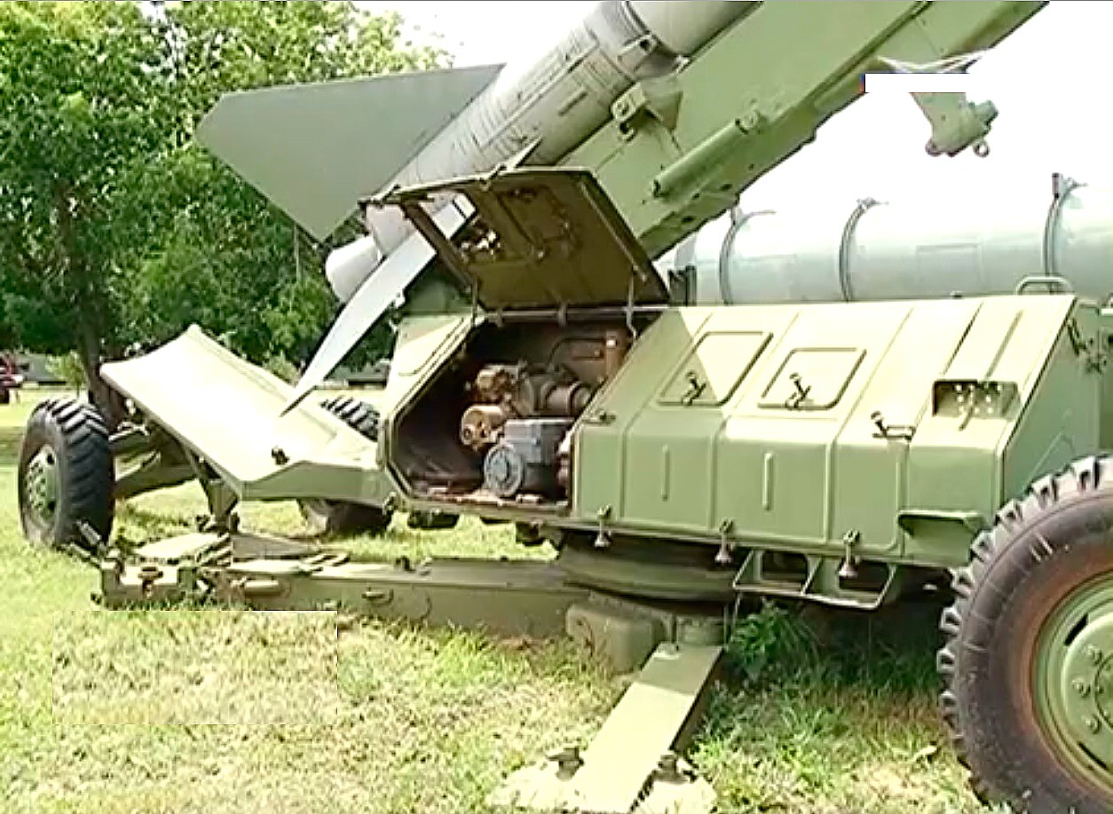
Soviet SA-2 missile system
The Soviets called it "S-75"
- https://en.wikipedia.org/wiki/S-75_Dvina
- https://fas.org/nuke/guide/russia/airdef/v-75.htm
- http://www.ausairpower.net/APA-S-75-Volkhov.html
|
I believe the Nevo SV, is an upgraded Spoon Rest as the article says.
From the little bit I know, the “Fan Song” and the “Spoon Rest” were used with the SA-2 I would guess the Spoon Rest was more like our HIPAR, long range acquisition. Both look like huge contraptions. |
Table of Contents
- from Thomas Wiegleb September 2018
- from Thomas Wiegleb October 2018
- from Thomas Wiegleb November 2018
-
from Thomas Wiegleb September 2018
|

from Thomas Wiegleb October 2018
|

from Thomas Wiegleb November 2018
via Greg Brown
Hi Greg,
will translate the basic training text in a silent hour.
Attached some pictures from the internet.
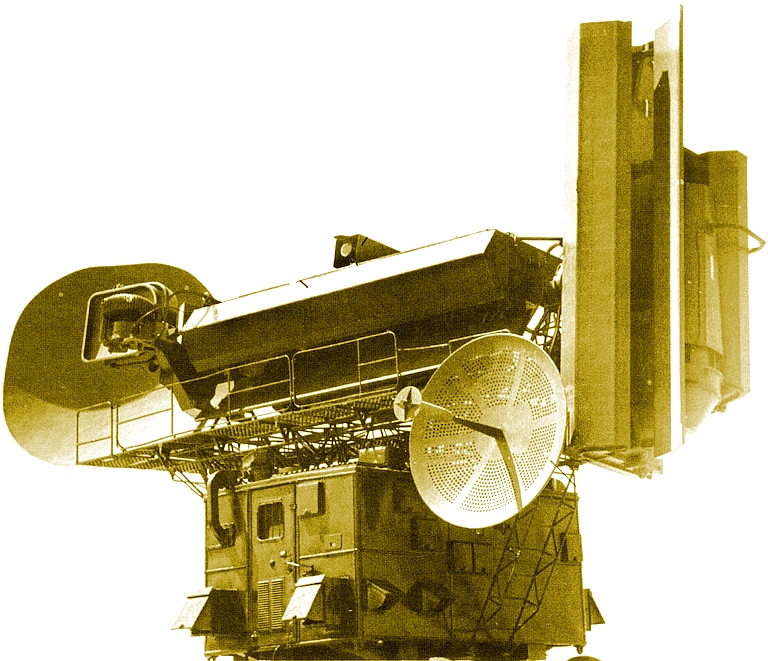
The matter: modernized S-75M4.
It has a changed antenna layout and probably some upgraded electronics.
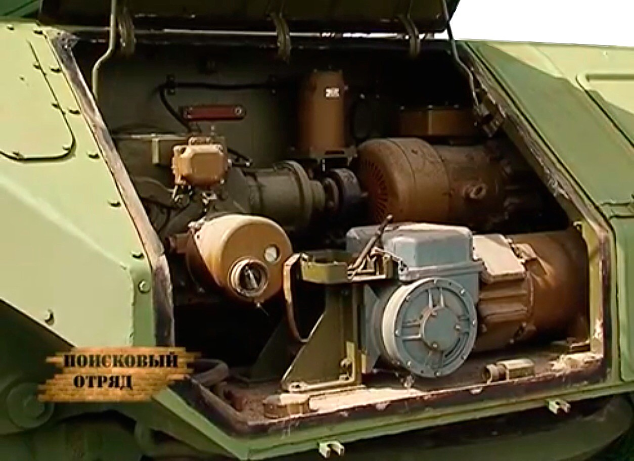
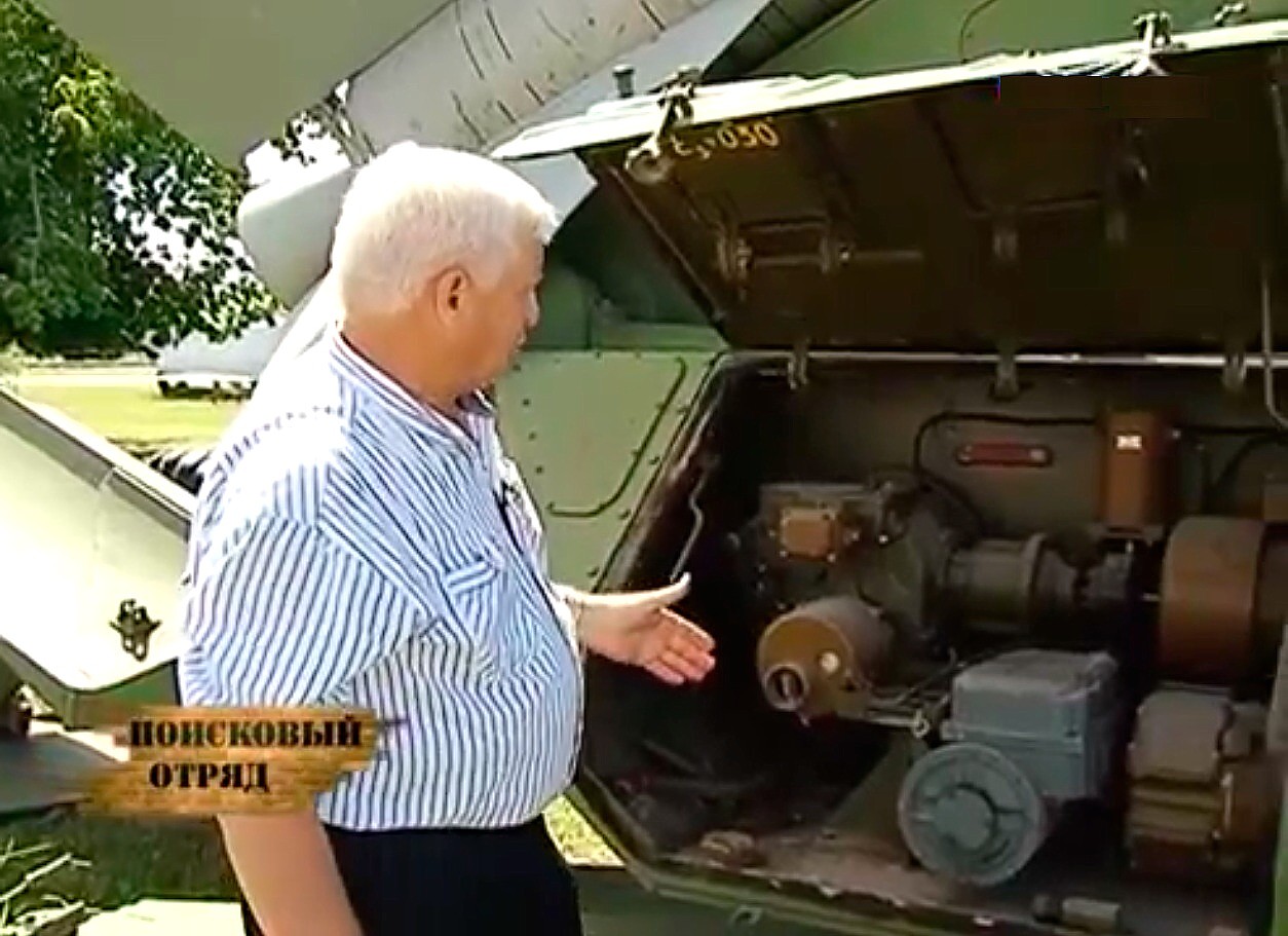
There are litle information about internals.
The narrow beam antenna on the left, where the missile uplink antenna was,
has similar assembly of the feed horns that can be seen on big surveilance and
fighter guidence radar stations P-35 and P-40.
THe shield plate between the transmitting and receiving horns is similar to those on the S-200.
The thing has kept the rotating feed horn, I assume used for sending only.
If they have made it as done before the rotating feedmotor can be halted in a centered postion
when using the "Podsvet" Ilumination mode.
This mode puts out the maximum power concentrated into a tiny small area.
It results in a big signal-noise-ratio even under havy ECM.
Imagine a fixed pencil beam for sending.
Another remarkable speciality, the have shifted the Epsilon and Beta-antennas into on assembly.
This reduces the distance between the two beams.
Let me think of DVD optical systems with half translucent mirrors.
It puts two beams onto one optical axis.
The misslie uplink antenna has moved to the right side.
An improved teleoptical vizir can be seen on top of wide beam antenna.
Cheers
Thomas
Hi Greg,
anothe note.
The russian designation has the word mestno in. Mestno is for local, but
it could mean steady as well.
I assume it means the Beta leveel does not has the scanning motor.
It is simply a pencil beam to put as much as possible power toward the
target.
The other antenna has the sanning motor and gives a wider scanarea . Don
not know, just the iidea.Oh anfd again, the plate has both function united.
THe plate makes the a reflector for the Epsilon AND Uglomestnuy AND the
separating shield as well.
Hu.Done.
This should fit.
Cheers
Thomas
hi Greg,
ohm old eyes.
Have seen on the attached picture how the do it.
I was right about the beamforming of two systems in line.
See the arrows, it gives the explanation.
THe shielding pate is the first reclector next to the feed horn (big
square). But it belongs to the "Uglomestnuy" level, tilted 90 against
the azimuatlny level.
Of course it separates the levels.
Cheer
Thomas
i Greg,
it has a small flaw.
The formentioned shielding plate is the reflector.
The russian designation "Konterreflector" of the "Oblutchatchel
azimutnaja ploskosti"
"Iluminator azimutal level" or so.
Update with some clarifications and some guesswork
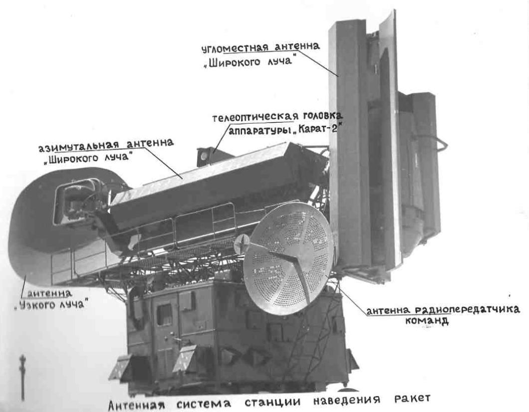
The matter: antenna layout of the modernized S-75M4.
It has a changed antenna layout and probably some upgraded electronics.
There are litle information about internals.
The narrow beam antenna on the left, where the missile uplink antenna was,
has an assembly of a group of feed horns that can be seen on big
surveilance and fighter guidence radar stations P-35 and P-40.
The plate between the transmitting and receiving horns works similar to
those on the S-200 and the S-300 NWO.
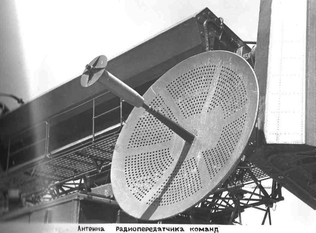
As done with the S-75M3 the now foremost UL antenne shows off a
rotating feed horn motor.
If they have made it as done before the rotating feedmotor can be halted
in a centered postion
when using the "Podsvet" Illumination mode.
This mode puts out the maximum power concentrated into a tiny small area.
Imagine a fixed pencil beam for sending.
It results in a big signal-noise-ratio even under receiving heavy ECM.
In this mode the echo signals from targets get received trough the wide
beam antennas.
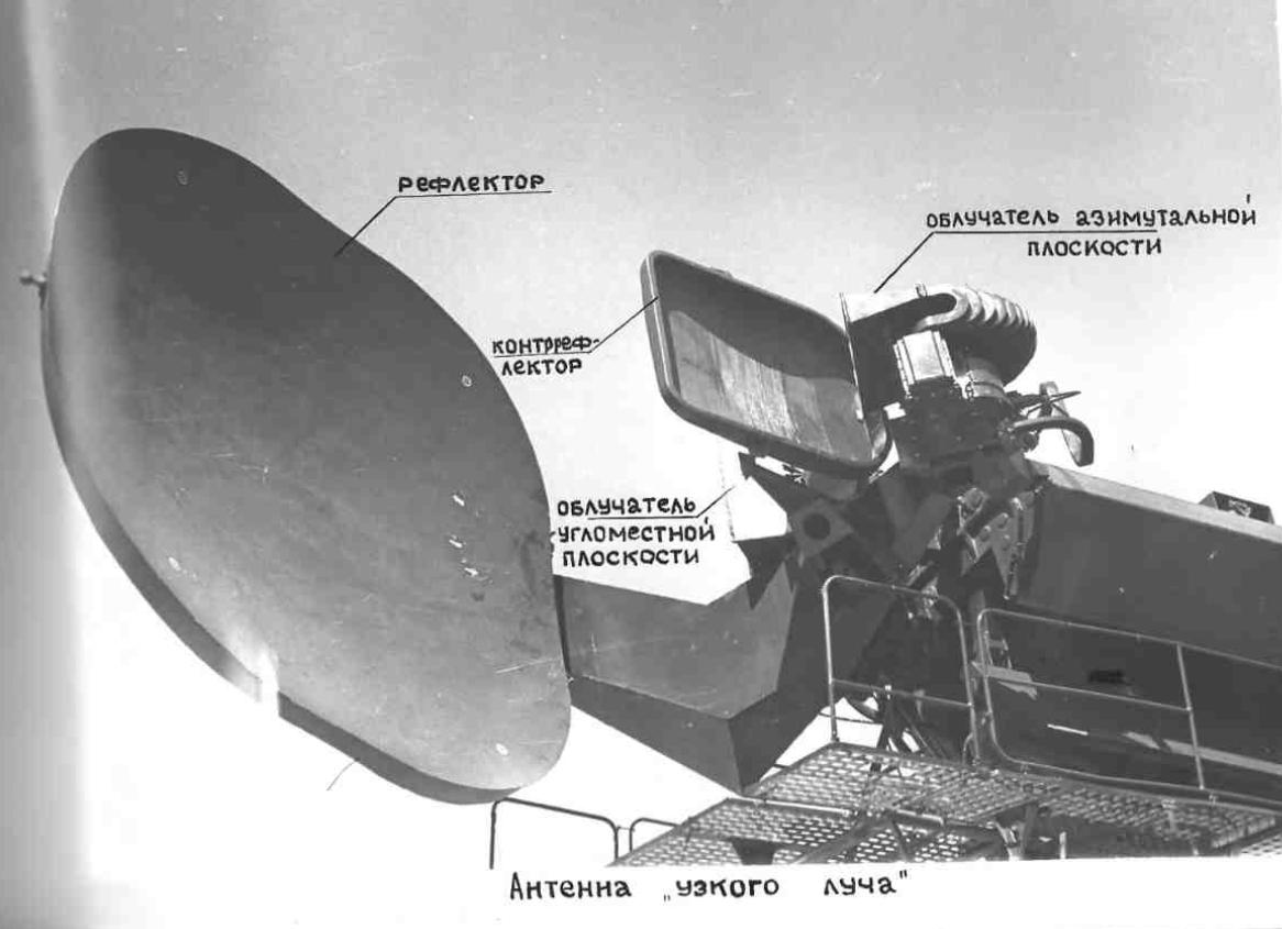
Another remarkable speciality, they have shifted the Epsilon and
Beta-antennas into one assembly.
This reduces the distance between the two beams much, to almost zero.
In reallity it puts two beams onto one optical axis. Great!
The misslie uplink antenna has moved to the right side.
An improved teleoptical visir can be seen on top of wide beam antenna.
About the beamforming of the two systems in line.
See the arrows, it gives the explanation.
The first reflector used for BOTH antennas makes a shielding plate as well.
It separates the transmission and receiving tracts (receiving is
depending on the mode UL or Podsvet).
I assume the Beta level does not has a scanning motor. Hard do say.
At least it seems to be hiden from plain sight.
Probably it makes simply a pencil beam to put as much as possible power
toward the target.
Notes regarding the markings on the pictures:
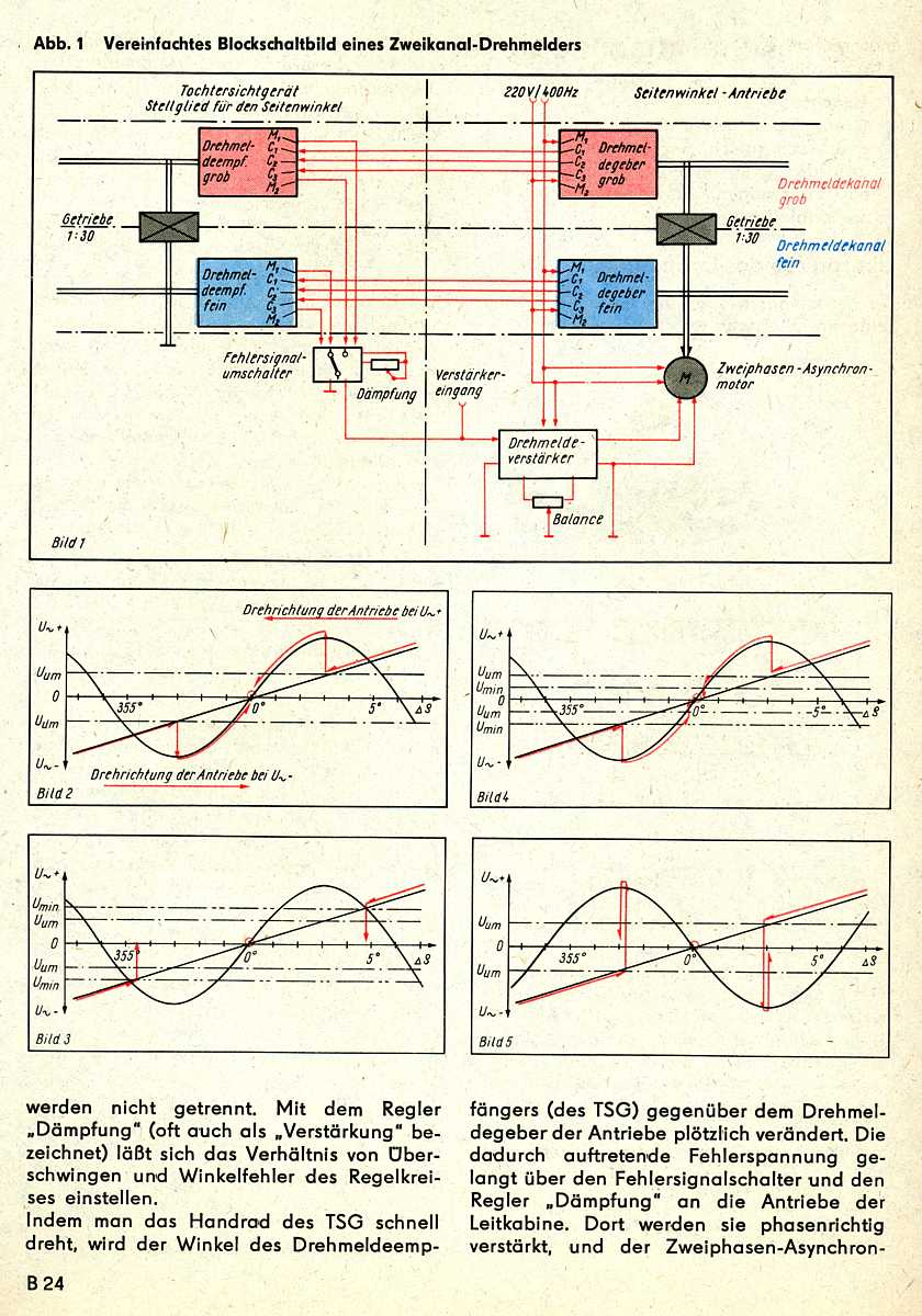
the level sideward, Uglomestnuy = old german was Ortswinkel, we called
it "Seitenwinkel"
the level upward, Azimutalny= Höhenwinkel
Cheers
Thomas
