Note: this entire page is from
http://www.usarmygermany.com/Sont.htm?http&&&www.usarmygermany.com/Units/Air%20Defense/USAREUR_ADA%20Overview%201.htm#M33
Permission requested 6/17/2014 -
Permission granted 6/18/2014 by Walter Elkins (usarmygermany.com), :-)) long active in
German oriented Nike web sites :-)) had lost contact with him -
M33 -- Antiaircraft Fire Control System
1950s
|
(Source: TM 9-6092-1-1, Antiaircraft Fire Control System M33C and M33D Operation, June 1956)
Section II. DESCRIPTION OF THE ANTIAIRCRAFT FIRE CONTROL SYSTEM M33 |
|
4. General
- This section contains a general description of the antiaircraft fire control system M33 (AA FCS M33). It is intended to acquaint operating personnel with the location and function of the components involved in the operation of the system.
- The principal components of the AA FCS M33 are the acquisition antenna assembly, tracking antenna, radar cabinet, computer, tactical-control console, and the tracking console. This system, with its equipment, is normally issued to the troops and transported in three trailers (figs. 1 and 2) as described in (1) through (4) below.
- All of the principal components, except for the acquisition antenna assembly, are permanently installed in, or mounted on, the M242 fire-control mount trailer.
- The acquisition antenna is transported on the M243 fire-control platform trailer. When the antenna is emplaced, the trailer is packed off site.
- All of the spare parts, tools, and some of the equipment are carried in the M244 firecontrol van trailer. This trailer has a working area for the performance of authorized repairs.
- The 11 reels of cable, used to interconnect various portions of the AA FCS M33, are transported by the using organization in general cargo prime movers on system serial numbers 132 through 682. On system serial numbers 682 and higher, an M36C truck replaces the M243 fire-control platform trailer. The M36C truck is used to transport the acquisition antenna and the antenna erecting equipment. In addition, storage space is provided on this truck for transporting the 11 reels of cable used to interconnect the various portions of the AA FCS M33. Descriptive information and instructions covering operation and organizational maintenance of the M36C truck will be provided at a later date.
- These trailers are capable of traversing the same terrain as the antiaircraft guns; on long moves, the trailers may be transported by rail, ship, or aircraft. Instructions covering operation and organizational maintenance of the trailers will be furnished in a separate manual. However, because of the operational usage of the trailers with the basic fire control systems, certain operational procedures are included in this manual.
- The designations M242, M243, and M244 apply to the unloaded trailers. Different designations are used to identify the trailers with electronic equipment as outlined in (1) through (3) below.
- Fire-control-system trailer designates M242 trailer with electronic equipment.
- Acquisition-antenna trailer designates M243 trailer with electronic equipment.
- Maintenance-and-spares trailer designates M244 trailer with electronic equipment.
- The AA FCS M33 is a mobile, integrated, electromechanical fire control system. It is capable of locating and displaying high-speed targets within the defense area, and supplying firing data to direct accurately the fire of 90-mm or 120-mm antiaircraft guns. To accomplish its mission, the AA FCS M33 requires from outside sources only primary power, early warning information, and meteorological data. Provision for installing identification friend or foe equipment (IFF) is incorporated in the system. Included in the AA FCS M33 are an acquisition radar, tracking radar, and a computer. Information from the acquisition and tracking radars, required to direct operation of the antiaircraft battery, is presented at a tactical-control console which is included with the system. The acquisition radar continuously searches the defense area and presents target position information from all targets in this area. With the use of the associated IFF equipment, hostile targets may be determined. From the target display of the acquisition radar, any target may be selected and transferred to the tracking radar. While the acquisition radar continues to search the defense area, the tracking radar tracks the selected target and provides accurate present position information to the computer. On the basis of the present position information received from the tracking radar and the meteorological data received from outside sources, the computer automatically and continuously determines the firing data which is used to direct the guns and set projectile fuzes of the associated antiaircraft guns.
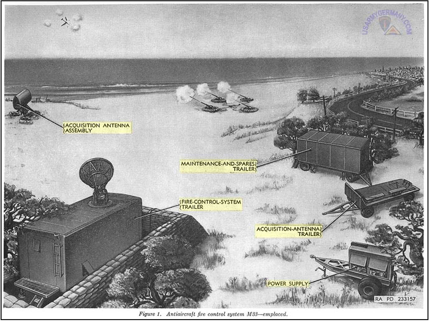 1. M33 -- emplaced (KB) |
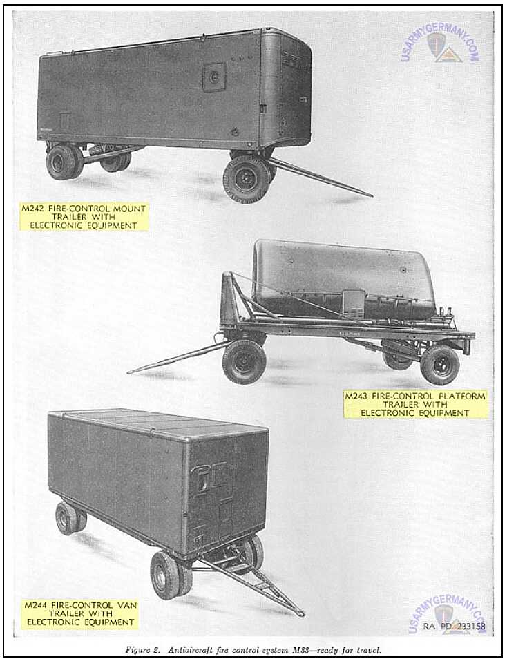 2. M33 -- ready to travel (KB) |
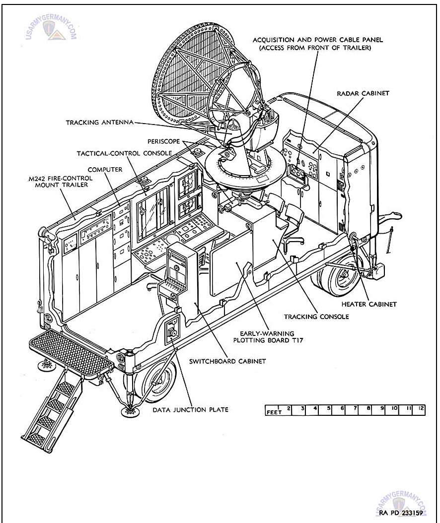 3. M242 trailer -- plan view (KB) |
5. Fire-Control-System Trailer
The fire-control-system trailer (fig. 1), when emplaced, serves as the operational center for the AA FCS M33. It includes the M242 fire-control mount trailer (fig. 3), which houses the other components of the fire-control-system trailer and the operating personnel. Inside the trailer, on the roadside of the trailer, are the computer and the tactical-control console. On the curbside of the trailer are the switchboard cabinet and the early-warning plotting board T17. Forward of the tactical-control console is the tracking console. At the front of the trailer are the radar cabinet and the heater cabinet. In some trailers, the heater cabinet has been replaced with a vehicle-mounting duct-type heater. Arranged at the various operator positions are chairs for the operators. Mounted on top of the trailer is the tracking antenna which includes the upper-section periscope. Portions of the tracking antenna, including the lower-section periscope, project into the interior of the trailer over the tracking console. Built into the exterior curbside wall of the trailer is the data junction plate which contains connectors for cables to the gun battery and a terminal strip for telephone connections. At the front of the trailer is the acquisition and power cable panel for cable connections to the acquisition antenna and the external power source. Air ports or vents for personnel and equipment ventilation are located in the front, rear, and roadside of the trailer.
6. M242 Fire-Control Mount Trailer
The M242 fire-control mount trailer (fig. 3) is designed to house the complex electronic equipment of the AA FCS M33 and to provide operating conditions for personnel which insure maximum efficiency and alertness. In addition to protecting the electronic equipment from the weather, the trailer permits operation and adjustments to the equipment when blackout restrictions are in force. The trailer is a full trailer, rather than a semi-trailer, to permit its being hauled over difficult terrain by a towing vehicle. Through use of special design features and light materials, the weight of the equipment is kept at a minimum value. The trailer can be sealed from light, dust, and water. With the door and all covers closed and secured, the fully loaded trailer can be floated upright without damage to the equipment. Jacks are built in at the four corners of the trailer to permit leveling, so that data will be accurately referenced to the horizontal plane. Spirit levels are used in leveling the trailer.
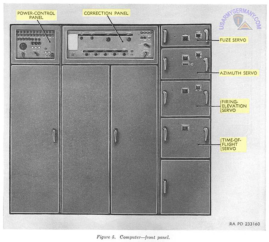
7. Computer
- The computer (fig. 3), when supplied with target position data by the tracking radar, determines firing azimuth and firing elevation data in mils and fuze data in fuze numbers. This data is supplied to the associated gun battery as electrical values.
- The computer (fig. 5) includes the power-control panel, correction panel, fuze servo, azimuth servo, firing-elevation servo, and time-of-flight servo in addition to electronic components. Controls for energizing the computer are mounted on the power-control panel. The correction panel contains controls for setting in battery parallax, ballistic, and meteorological data, and for displaying the data. The correction panel also contains controls for use in checking computer performance. The fuze servo contains controls and dials for correcting and indicating fuze data being furnished to the guns. Controls and dials for correcting and indicating firing azimuth data being furnished to the guns, and controls for setting in wind azimuth data are mounted on the front of the azimuth servo. The firing-elevation servo contains controls and dials for correcting and indicating the firing elevation data being furnished to the guns. Time of flight of the projectile to the predicted target position may be read on the dial of the time-of-flight servo.
- The computer has three types of prediction: linear, tangential, and quadratic. Linear prediction is used when the target is flying a straight non-accelerating course, tangential prediction when the target is flying a slightly curved or slightly accelerated course, and quadratic prediction when the target is flying a curved course or is accelerating rapidly. Selection of the type of prediction is made by controls on the target-rate indicator which is on the tactical-control console. From the information indicated on the dials of the target-rate indicator and the plotting boards, the type of prediction required for the computer may be determined.
- The computer is designed so that those parts depending on the ballistics of the gun and ammunition are replaceable. This makes it possible to use the system with 90-mm guns (M33C) and with 120-mm guns (M33D) by changing certain subassemblies of the computer.
8. Tactical-Control Console
- The tactical-control console (fig. 3) contains controls and provides a display of information which permit intelligent direction of the firing of the battery. At the tactical-control console are positions for the tactical-control officer, the acquisition-radar operator, and the computer operator.
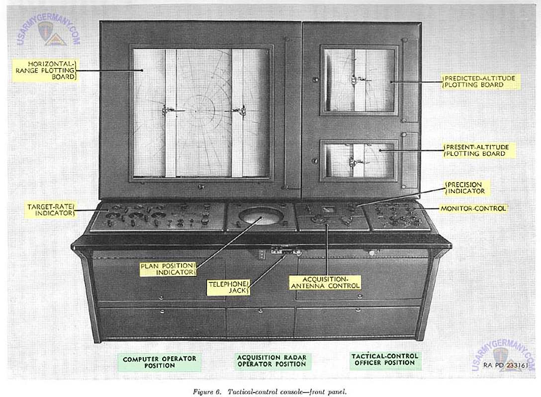
- Mounted on the sloping panel of the console (fig. 6) at the tactical-control officer's position is the monitor-control, which provides a signaling system for directing the operation of the AA FCS M33 and the guns of the battery. This signaling system provides a more rapid and dependable control of the battery than could be obtained by the use of the telephone alone. Through the use of colored signal lights, the tactical-control officer can see at a glance the state of readiness of the guns and all parts of the fire control system. By means of controls, he can challenge a target and indicate to the members of the battery whether the challenged target is hostile or friendly. Also, by controls operating signal lights and horn, he gives the order to commence fire or to cease fire. Circuits are arranged so the commence fire signal cannot be given until certain parts of the battery are ready.
- From the tactical-control officer's position, the control officer can see the early-warning plotting board and observe the target through the periscope of the tracking antenna (fig. 3).
- At the acquisition-radar operator's position are a 10-inch plan-position indicator (PPI), an "expanded B" precision indicator, and the acquisition-antenna control. The indicators are visible also to the tactical-control officer.
- The PPI displays all targets within 6,400 mils of azimuth and 60,000 or 120,000 yards of range. Special moving-target-indicator circuits eliminate the presentation of nearby stationary targets, permitting only moving targets to be displayed. The PPI displays an acquisition range mark and a steerable azimuth line. These marks are used for designating targets in range and azimuth. Also appearing on the PPI is an electronic cross which indicates the range and azimuth setting of the tracking radar. This electronic cross enables the tactical-control officer to note the location of the target being engaged.
- The precision indicator displays an enlarged portion of the PPI presentation. It is centered about either the electronic cross of the tracking radar or the azimuth line and range circle of the acquisition radar.
- The acquisition-antenna control permits positioning of the steerable azimuth line and acquisition range mark to designate a target. The acquisition-antenna control may be used to follow and point out the next target to be engaged, while the tracking radar is tracking the target previously designated.
- The target-rate indicator, located at the computer operator's position, provides meters which indicate the target's tactics and serve as the basis for determining the computer type of prediction. Controls for selecting the computer type of prediction and the plotting boards mode of operation are located on the target-rate indicator panel. Also located on this panel are signal lights and controls for regulating illumination of the tactical-control console, plotting boards, and computer servos.
- A telephone jack is secured to the underside of the shelf of the tactical-control console.
- Mounted above the sloping panel of the tactical-control console are three automatic plotting boards which accurately plot the course and tactics of the target, and the location of future target positions with respect to any areas in which firing may be restricted. In addition, the plotting boards may be used to check the performance of the tracking radar and computer. These boards are the horizontal-range, present-altitude, and predicted-altitude plotting boards.
- The horizontal-range plotting board plots a continuous record in the horizontal plane of both the present position and predicted position of the target. The plotting board also plots fire, cease fire, and 20-second timing marks to give a permanent plot of a target engagement for future study and evaluation. A series of concentric range circles and radial azimuth lines are engraved in the transparent plastic backboard and appear behind transparent plotting paper. This provides a means of reference, since the origin of these coordinates corresponds to the gun directing point. Variable intensity lights behind the plastic backboard illuminate the plot. The 1:100,000 scale allows the use of standard military maps to make overlays to be used behind the plot. The overlays show such things as the locations of the objectives being defended and the restricted areas into which shells should not be fired.
- The present-altitude plotting board plots the present altitude of the target against the present ground range of the target. The plotting board also plots fire, cease fire, and 20-second timing marks. A series of slant range circles in 5,000-yard steps are inscribed on the plastic backboard, together with horizontal altitude lines in 2,000-yard steps. The origin of these coordinates corresponds to the tracking antenna and is located near the lower left corner of the board.
- The predicted-altitude plotting board plots the predicted altitude of the target against the predicted ground range of the target. The plotting board also plots fire, cease fire, and 20-second timing marks to give a permanent plot of a target engagement for future study and reference. A series of gun trajectory curves in steps of 20-mil elevation and time-offlight arcs in 5-second steps are inscribed on the plastic backboard. Because gun trajectories and time of flight are a function of the particular type of gun, the plastic backboard used for the M33C differs from that used for the M33D. The origin of these coordinates corresponds to the gun directing point and is located near the lower left corner of the board.
9. Early-Warning Plotting Board T17
The early-warning plotting board T17 (fig. 3) is a manually operated plotting board upon which plotted information received by telephone from the early-warning radar net is recorded. Target data up to a maximum of 250,000 yards may be plotted on the plastic board (fig. 7) with a wax pencil. A series of concentric range circles and radial azimuth lines, engraved in the transparent plastic plotting board, provide a means whereby any approaching targets may be plotted fairly accurately. A telephone jack is mounted at the bottom of the board.
5. Computer (KB)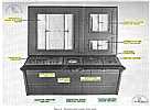
6. Tactical-control console (KB)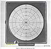
7. Early-warning plotting board (KB)10. Swtichboard Cabinet
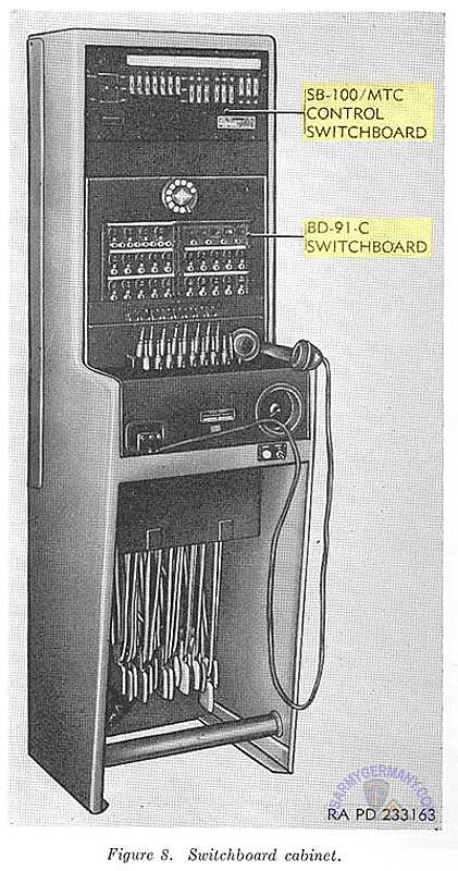
- The switchboard cabinet (figs. 3 and 8) contains switchboards BD-91-C and SB-100/MTC. It provides line and hot-loop communications within the battery, lines to units outside the battery, and trunk lines to early warning nets or higher echelons through a dial system.
- The BD-91-C switchboard contains 20 typical field line circuits, four trunk line circuits, a four-jack conference circuit, a night-alarm buzzer circuit, operator's telephone jack, and an automatic dial for use with trunk circuits. The 20 field line circuits make use of the equivalent of magneto ringing, portable, field telephone sets. Seven line circuits and the four trunk line circuits are connected directly to their assigned points. The assigned points are the tactical-control-console telephone jack (fig. 6), the early-warning-plotting-board telephone jack (fig. 7), and the data junction plate (fig. 3). The other 13 line circuits are controlled by the SB-100/MTC switchboard.
- The SB-100/MTC switchboard contains a battery commander's telephone jack, a LOOP 1-LOOP 2 switch, a RELEASE-TEST switch, and slide switches for selecting individual lines to be transferred into one of two loop circuits. When the BATTERY ALERT switch is depressed, the individual field lines either remain connected directly to the BD-91-C switchboard or are interconnected into one of two loop circuits, depending on the position of the pertinent slide switch or switches. The telephone lines are usually connected into the loop circuits as outlined in (1) through (4) below.
- Telephone lines within the firing battery proper are usually connected into the loop 1 circuit. The telephone jacks for these lines are located at the generator, acquisition RF coupler (fig. 17), guns, tracking console (fig. 9), and M242 fire-control-mount-trailer roof (fig. 65). In addition, two square lines are provided for use if necessary.
- The four telephone lines in the perimeter defense (machineguns No. 1, No. 2, No. 3, and No. 4) are permanently connected into the loop 2 circuit and no slide switches are provided for these lines.
- The telephone line for the battery executive may be connected into the loop 1 circuit, loop 2 circuit, or the BD-91-C switchboard, by adjusting the pertinent slide switches to the desired position. Also available are two spare telephone lines which can be connected in a similar manner.
- In addition, the battery commander may use the jack on the SB-100/MTC switchboard and converse with either of these loops by operating the nearby LOOP 1-LOOP 2 switch. The same applies to the telephone jack at the tactical control console (fig. 6) where there is a similar LOOP 1-LOOP 2 switch.
- When deemed necessary, commercial telephone lines have been connected into the M242 trailer. The commercial telephone cable containing the individual lines may be run directly from outside telephone facilities into the trailer through a hole drilled in the data junction plate or the cable may be connected to a connector installed at the data junction plate. The commercial telephone lines are terminated at three jacks which are installed at the early-warning plotting board, tracking console, and tactical-control console. These commercial telephone circuits operate independently of the telephone switchboard.
- Additional information on switchboard BD91-C and SB-100/MTC is contained in TM 11-4313 and TM 11-2133, respectively.
11. Tracking Console
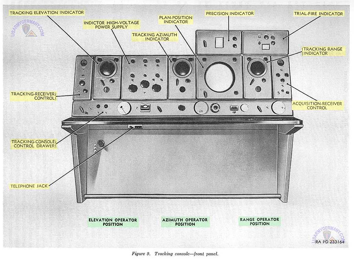
- The tracking console (figs. 3 and 9) provides indicators and controls for observing and tracking the target designated by the tactical-control officer. At the tracking console are positions for the elevation operator, azimuth operator, and range operator.
- The tracking console contains the front panel assemblies described in (1) through (9) below.
- Three tracking indicators which display tracking marks and target video.
- A PPI which is identical to and displays the same information as the PPI on the tactical-control console.
- A precision indicator which is identical to and displays the same information as the precision indicator on the tactical-control console.
- A trial-fire indicator which provides means for observing range deviations during trial-fire and velocity-fire tests.
- A tracking-receiver control which contains controls and indicators used in making remote adjustments to the tracking radar receiver.
- An acquisition-receiver control which contains controls and indicators used in making remote adjustments to the acquisition radar receiver.
- An indicator high-voltage power supply with mounted signal indicator lights and controls which are a part of the signaling system of the tactical-control console. Also mounted on the indicator high-voltage power supply are controls for varying the brightness of the signal indicator lights, dial lights, and the ceiling lights near the tracking console.
- A tracking-console control drawer which contains controls used in tracking a target in manual or aided operation. The control drawer also contains controls for selecting the mode of operation and other miscellaneous operating controls.
- A telephone jack which is attached to the underside of the tracking console shelf.
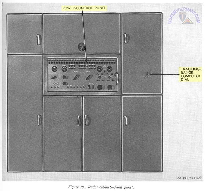
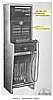
12. Radar Cabinet
The radar cabinet (fig. 3) houses many of the assemblies of the acquisition and tracking radars. Mounted in the center of the cabinet is the power-control panel (fig. 10). On the panel are controls for energizing and making operating adjustments to the radars. In the upper right panel is the tracking-range-computer dial on which the setting of the tracking range computer may be read in yards.13. Heater Cabinet
(not transcribed)14. Vehicle-Mounting Duct-Type Heater (not transcribed)
8. Switchboard cabinet (KB)
9. Tracking console (KB)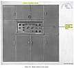
10. Radar cabinet (KB)15. Tracking Antenna
- The tracking antenna (fig. 3) radiates a sharply focused pencil beam in a conical path. It receives pulses reflected from any target upon which it may be directed. The antenna is capable of moving through 6,400 mils of azimuth and from -180 mils to + 1,600 mils of elevation.
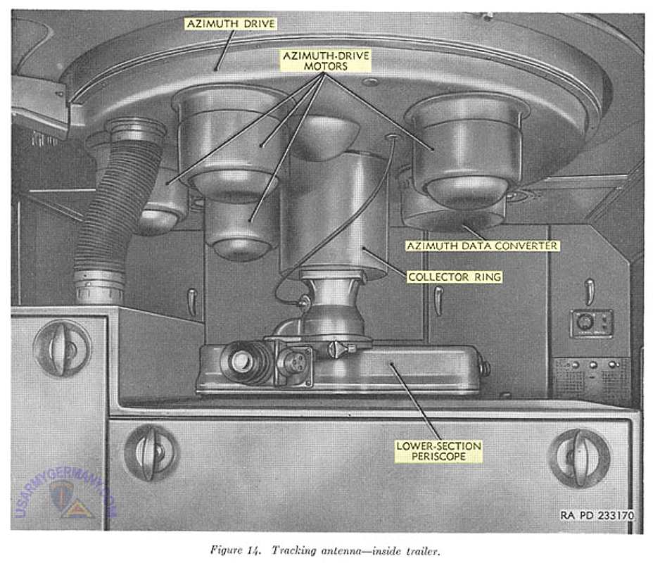
- When emplaced, a portion of the tracking antenna (fig. 13) is mounted on the turntable of the azimuth drive on top of the M242 trailer. The remainder of the antenna is built into the trailer roof above the tracking console (fig. 14). The portion of the tracking antenna mounted on top of the trailer consists of the tracking RF coupler, tracking elevation drive, elevation-drive supports, tracking wave-guide lens, upper-section periscope, and the tracking-lens mounting, which consists of the upper lens mounting, lower lens mounting, upper hensmounting supports, and ring support.
- The tracking RF coupler contains electronic assemblies associated with the tracking radar. The elevation drive moves the antenna in elevation. The elevation-drive supports, mounted on the azimuth drive turntable, hold the assemblies mounted on them in place in azimuth while allowing motion in elevation. The wave-guide lens, supported by the lens mounting, focuses the transmitted pulses and received pulses. The upper-section periscope with the lower-section periscope (fig. 14) inside the trailer make up the periscope assembly which provides optical tracking. Also inside the trailer mounted in the roof are the azimuth drive, azimuth data converter, and collector ring. The azimuth drive moves the antenna in azimuth. The azimuth data converter supplies azimuth data to the computer, and collector rings provide electrical connections between the rotating and stationary portions of the antenna.
- When ready for travel, the components mounted on the trailer roof are stored behind the clamshell doors at the front of the trailer (fig. 15) and inside the trailer. Those components of the tracking antenna mounted in the trailer roof are not removed for travel.
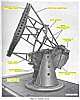
16. Acquisition Antenna Assembly
- When emplaced, the acquisition antenna assembly (fig. 1) is located within 250 yards of the fire-control-system trailer. The acquisition antenna assembly (fig. 17) includes the antenna, acquisition-antenna drive, acquisition RF coupler, acquisition modulator, acquisition-antenna mounting legs and leg braces, acquisition-antenna leveling jacks, acquisition-antenna orientation test set, and interconnecting cables.
- The antenna focuses and radiates transmitted pulses in either a pencil-shaped beam or a cosecant-squared beam. It normally rotates continuously through 6,400 mils of azimuth. The antenna also picks up the signals reflected by targets and directs them to the acquisition RF coupler.
- The acquisition-antenna drive contains a motor which rotates the antenna at speeds of 10, 20, or 30 revolutions per minute. It also provides a rotary connection between the rotating antenna and the stationary RF coupler. Controls for orienting the acquisition antenna are provided inside the acquisition orient compartment (fig. 17). The acquisition RIF coupler and acquisition modulator contain electronic assemblies associated with the acquisition radar. The antenna mounting legs, leg braces, and jacks support the emplaced acquisition antenna assembly.
- The acquisition-antenna orientation test set includes two spirit levels for leveling the acquisition antenna assembly and a peep sight for orienting the antenna.
- When ready for travel, the antenna drive, RF coupler, modulator, and mounting legs are carried inside the M244 fire-control van trailer. The antenna and erecting equipment are carried on the M243 fire-control platform trailer (fig. 2).
17. Acquisition-Antenna Trailer
The acquisition-antenna trailer (fig. 1), which includes the M243 fire-control platform trailer, provides means for transporting the antenna of the acquisition antenna assembly and equipment used in erecting the acquisition antenna assembly.18. Maintenance-and-Spares Trailer
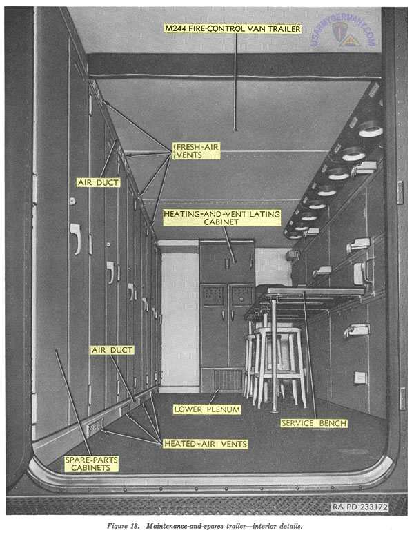
- When emplaced, the maintenance-and-spares trailer (fig. 1) serves as a maintenance workshop. The trailer (fig. 18) includes the M244 fire-control van trailer, a heating-and-ventilating cabinet, a service bench, and cabinets which provide storage for organizational tools, equipment, and spare parts. The trailer contains ventilation openings for personnel, a lighting system, and blackout curtains.
- During transit, the acquisition-antenna drive, RF coupler, modulator, and mounting legs are carried in the trailer. This trailer can be scaled from light, dust, and water and can be floated upright when all doors and covers are closed and secured.
13. Tracking antenna (KB)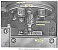
14. Tracking antenna -- inside trailer (KB)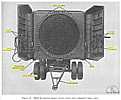
15. M242 trailer -- clamshell doors open (KB)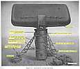
17. Acquisition antenna assembly (KB)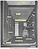
18. M244 trailer -- interior details (KB)19. Heating-and-Ventilation Cabinet
(not transcribed)End of Section II </