From the ICT 1301 Computer Restoration
International Computers and Tabulators (ICT)
Images of its
AMPEX TM-4 Tape Transports
Frank King found October 2012 media coverage, - please note that inspite of the article, your cell phone is at least 4 orders of magnitude faster and more capable than "Flossie".
in response to my special request.
|
In the early 1960s, about the time Roger Holmes' ICT 1301 was current,
I (Ed Thelen) was servicing General Electric Computer Department 225 computer systems.
These systems were equiped with
almost identical to those provided with Roger's ICT 1301. Web Site I fought with those transports (drives) on an almost daily basis for 2.5 years on a number of G.E. computer sites - and wanted some images for my tirade. The only GE-225 remaining is in a warehouse in Queensland, Australia. This is a bit out of my casual traveling range, but fortunately Roger Holmes, in Kent, England provided the following images :-)) |
| This two speed Capstan Drive Motor drove the belts that rotated the 1.5 inch steel capstans which moved the tape when the pinch roller was activated - usually 75 inches/second. 150 inches/second for rewind. |
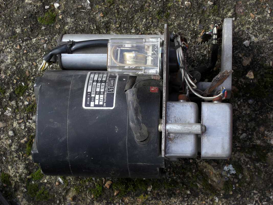
CapstanDriveMotorAssy | The little guy was synchronous (rotated exactly with the power line frequency) and could put out about 1/7 horse power - Roger weighed it at 13 pounds. |
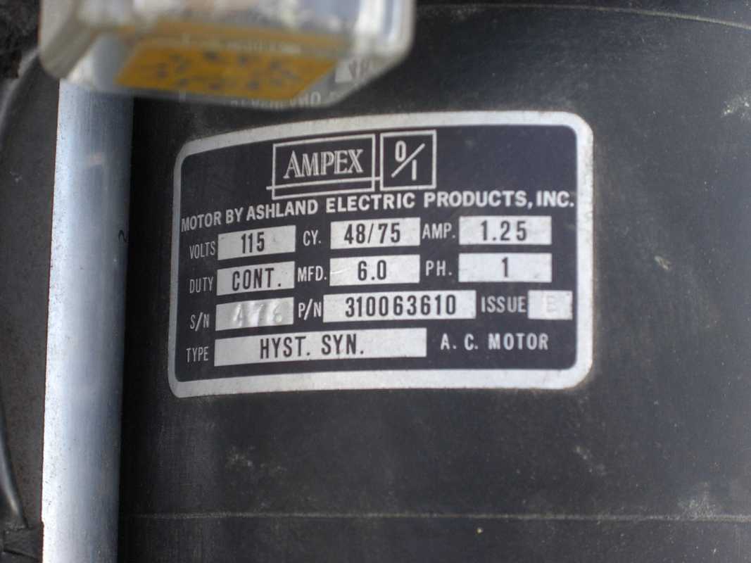
CapstanDriveMotorTag |
| This Reel Motor is a "Torque Motor", Direct Current, designed to start and stop a lot !! This type of mag tape unit did not rewind at about 3000 RPM as did the IBM drives - The rewind was at 150 inches/second. |
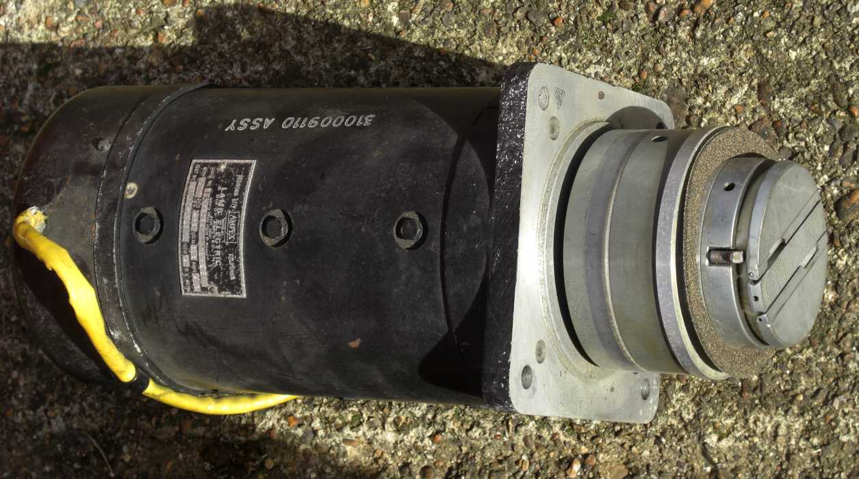
TorqueMotorSide | And the Name Plate for the torque motor, 110 volts dc, 4.5 amps. Rumor suggested it could twist your arm off. It was turned on and off by the positions of the tension arms. Roger says 33 pounds. |
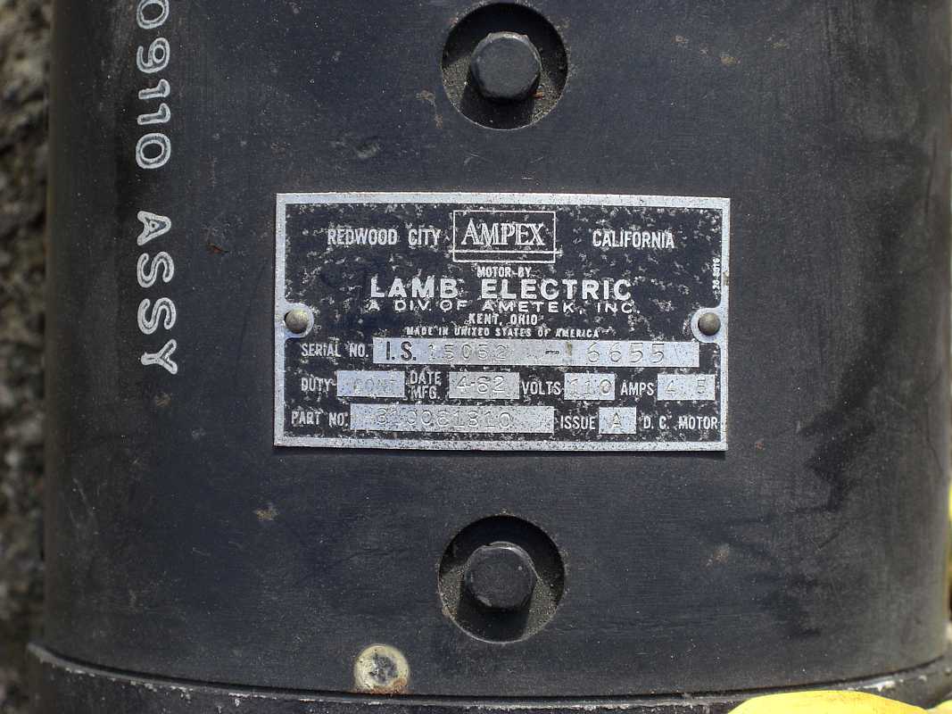
TorqueMotorNamePlate |
| To help buffer the sudden starts and stops of the tape and tape reels, AMPEX used tension arms and these little "pucker pockets" into which a vacuum pulled the tape. IBM used 3 foot columns. |

PuckerPocketWCoverClosed | The hardened glass covering the "pucker pocket" is opened, showing the steel hinge epoxied to it. Temperature extremes tended to break the glass in the region of the steel hinge. |
PuckerPocketWCover |
| The other side of the "pucker pocket" showing the connection to the vacuum cleaner motor supplying the vacuum.The GE version had a 4 foot hose to the vacuum motor. |
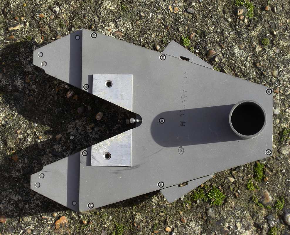
PuckerPocketVacuumAttachment | The blue handle/lever is shown closed. The operator pulls the lever open to change reels - this action pulls the tension arms (not shown) towards the pucker pockets to enabled threading the mechanism. |
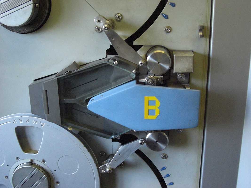
FrontOperatingHandleClosed |
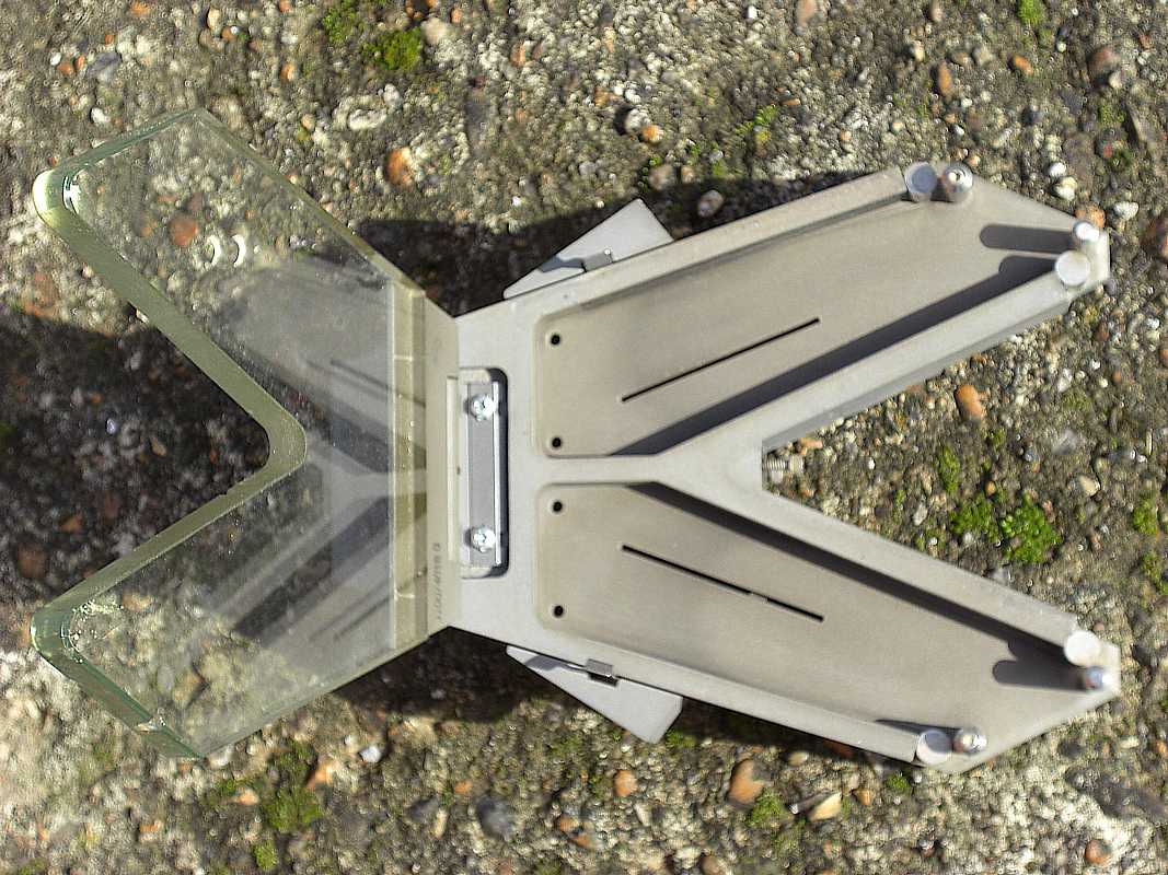
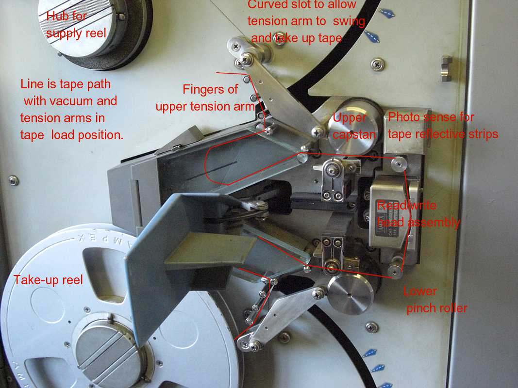
| The lever is shown open, and the tension arms (shown with the three little rollers) are in position to enable tape threading through the mechanisms. |
TapeHandling | The bottom is the big round steel capstan, with the (brown/black) rubber pinch roller next to it. (the top capstan and pinch roller not visible). The "I/O" box contains the seven read/write heads. The hinged plate (left) helps hold the tape against the heads. |
TopReadWriteHead- PinchRoller |
| The back of the swing out tape drive. Major components are labeled. On the GE varient, the vacuum motor is mounted elsewhere. (The boxes protect arm position sensors (contacts) and the servo dash-pot ) |
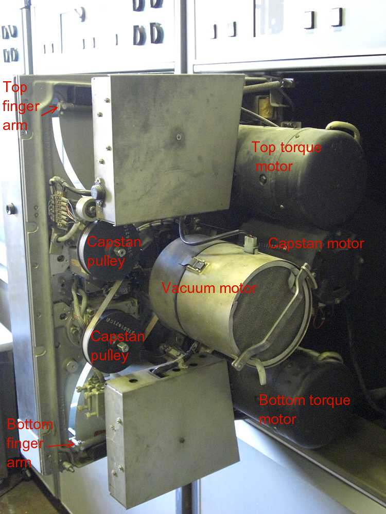
ICT-1301-59-BackSide | These two Capstan Pulleys rotated the 1.5 inch steel capstans seen on the front side, the operator side ;-)) |
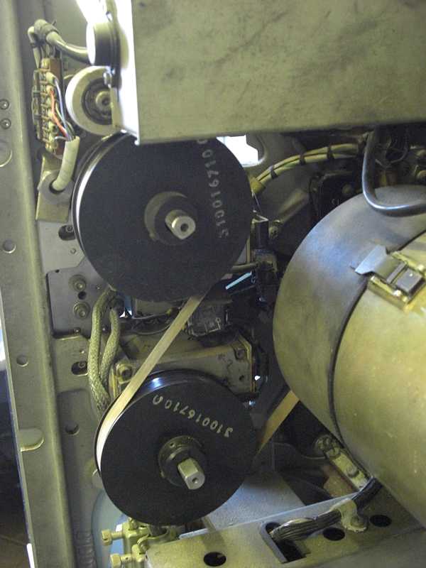
CapstanDrivePulleys |
| These cute little 2D21 thyratrons (about 2.5 inches high) switched over 600 volts to the pinch roller selenoids which started and stopped the magnetic tape. |
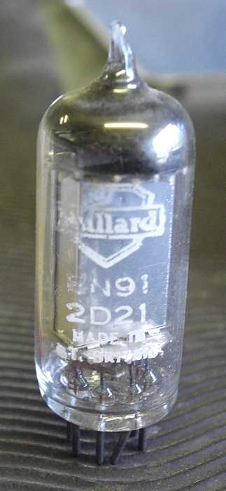
2D21-Thyratron | The GE varient had only the four little 2D21 tubes - I have no idea what this big C3J thyratron was supposed to do - |
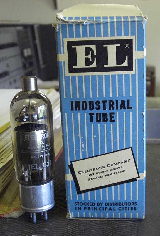
C3J-Thyratron |
| Roger Holmes' Tape Transport manuals - This inspired me to look on line for AMPEX TM-4 manuals - I just bought an SDS version of TM-4 from FSM Directory. |
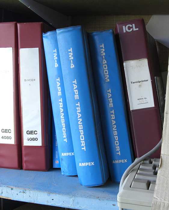
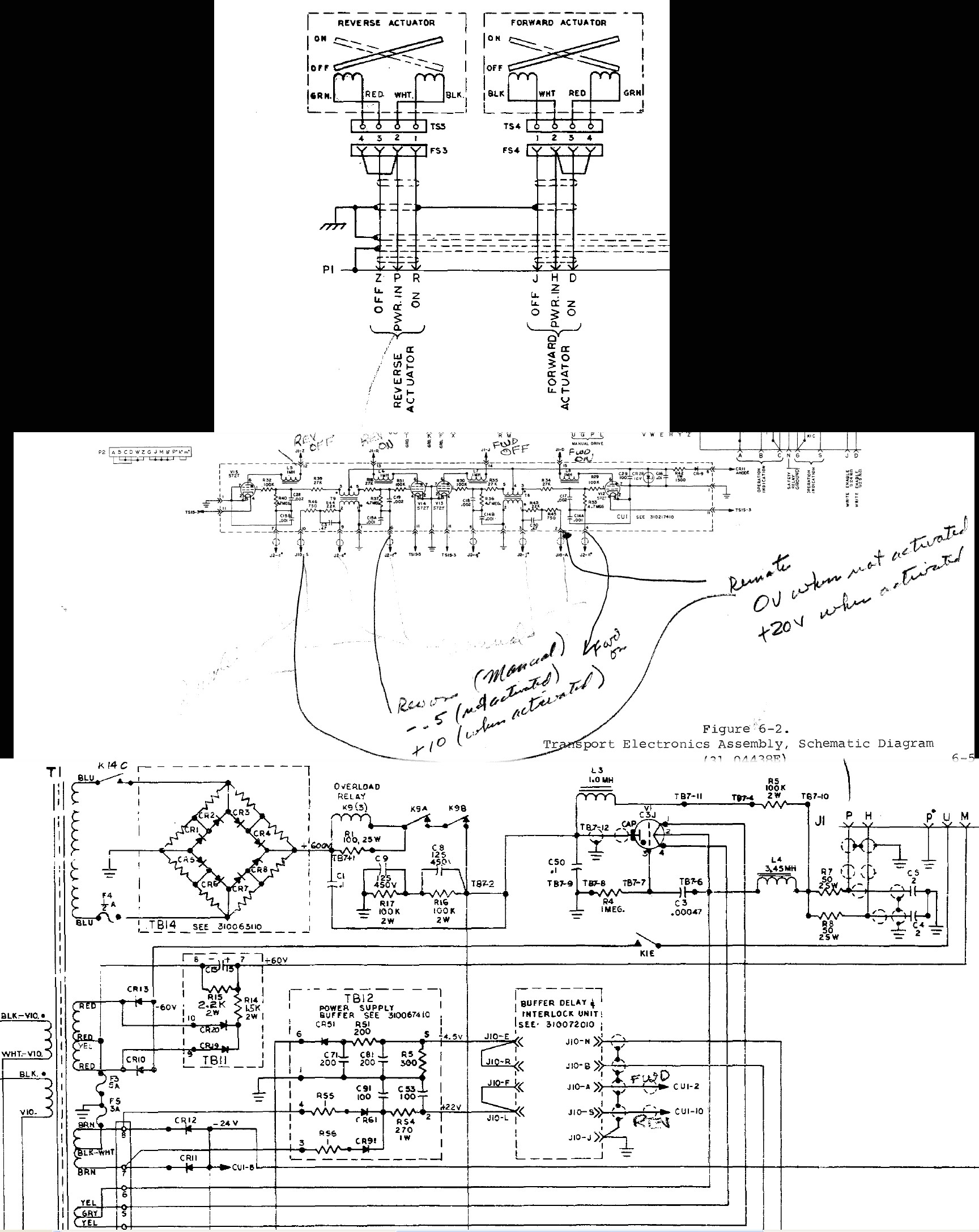
TM-4-Manuals | An electronic chassis- The GE varient had a much smaller chassis to drive the pinch-roller solenides only - the electronics to drive the pinch-rollers is summarized on this drawing 580 KBytes |
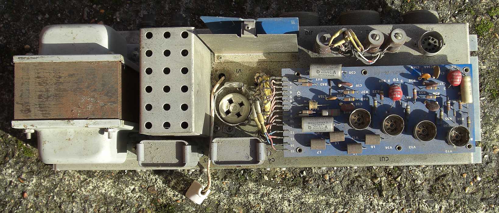
E-Chassis |
| The ceramic tube cap is for a C3J thyratron - this function not in the GE varient |

E-Chassis-side-b | ? Possibly the blue circuit cards are for the tape leader/trailer reflective foil sensing ? |
E-Chassis-side-p |
| One of the relays energized if over current from the pinch roller thyratrons. Also you can see the bridge rectifiers to make the 600 volts for the 2D21 pinch-roller thyratrons. |
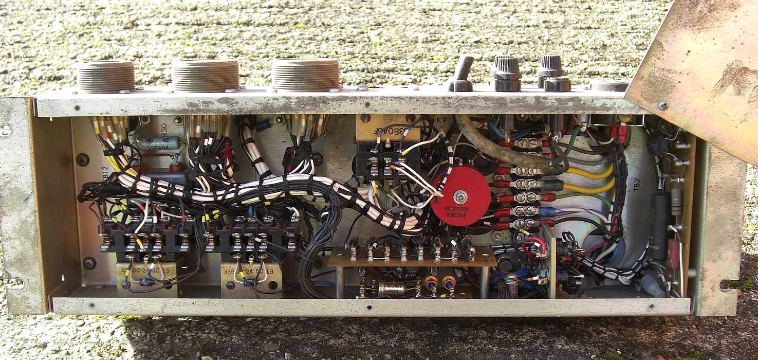
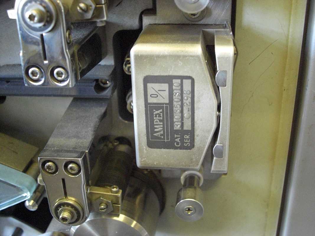
E-Chassis-bottom | Name plate on the Tape Transport, which is a swing out door. Note that it specifies the ICT varient or contract. |
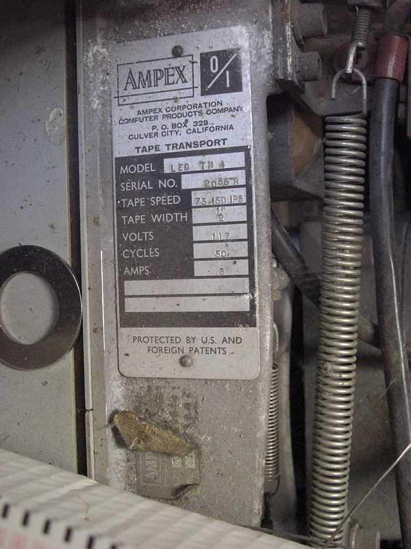
TM-4-tag-1 |
| This version of Reel Lock was after the screw twist original which quickly stripped the screw threads and became inoperable :-(( |
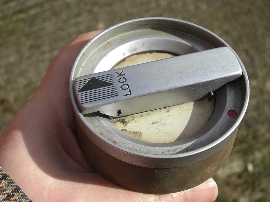
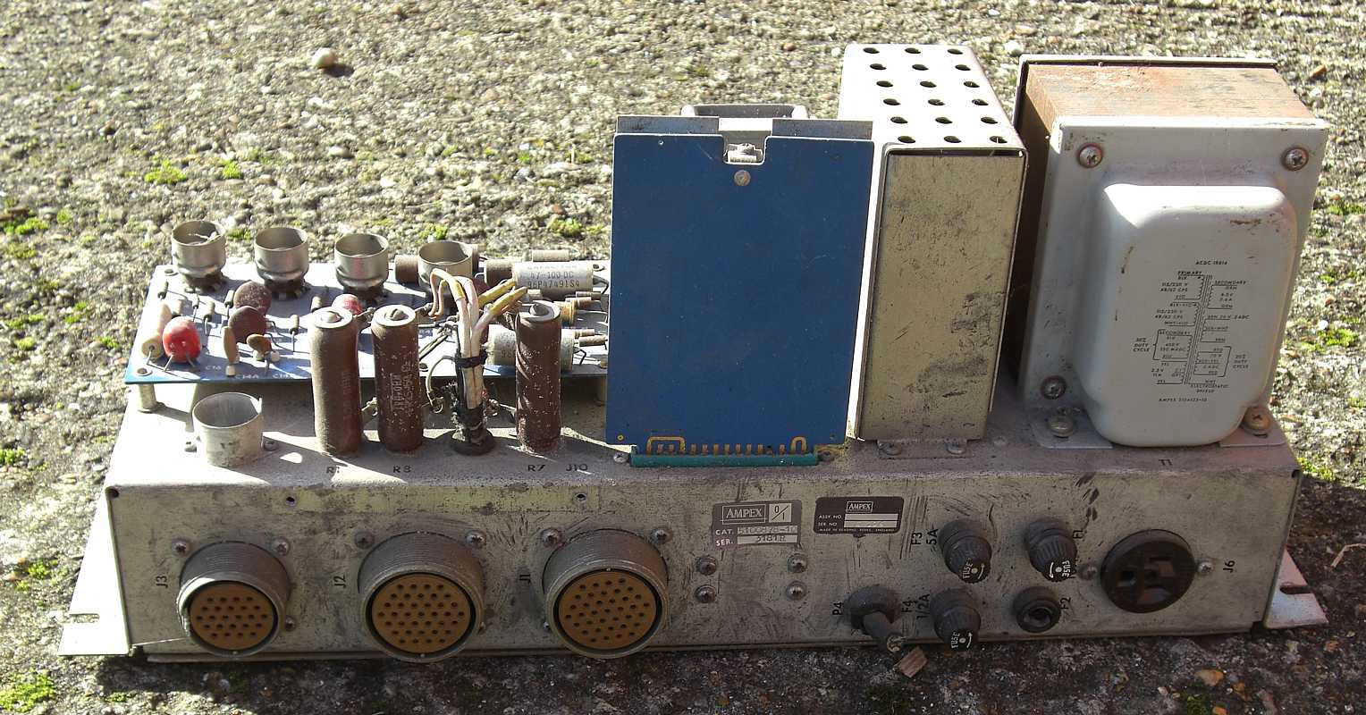
ReelLock-2 | I'm including this to show voltages unfamiliar to today's 5 or fewer volt computers. The thyratons used 600 volts. The peak value of 400 volts RMS. |
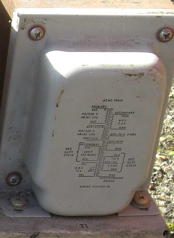
E-Chassis-side-transformer |
SDS version of Ampex TM-4 manual, 11 megabytes