Converting a Family Car to Electric
A big project done by Carl Thelen
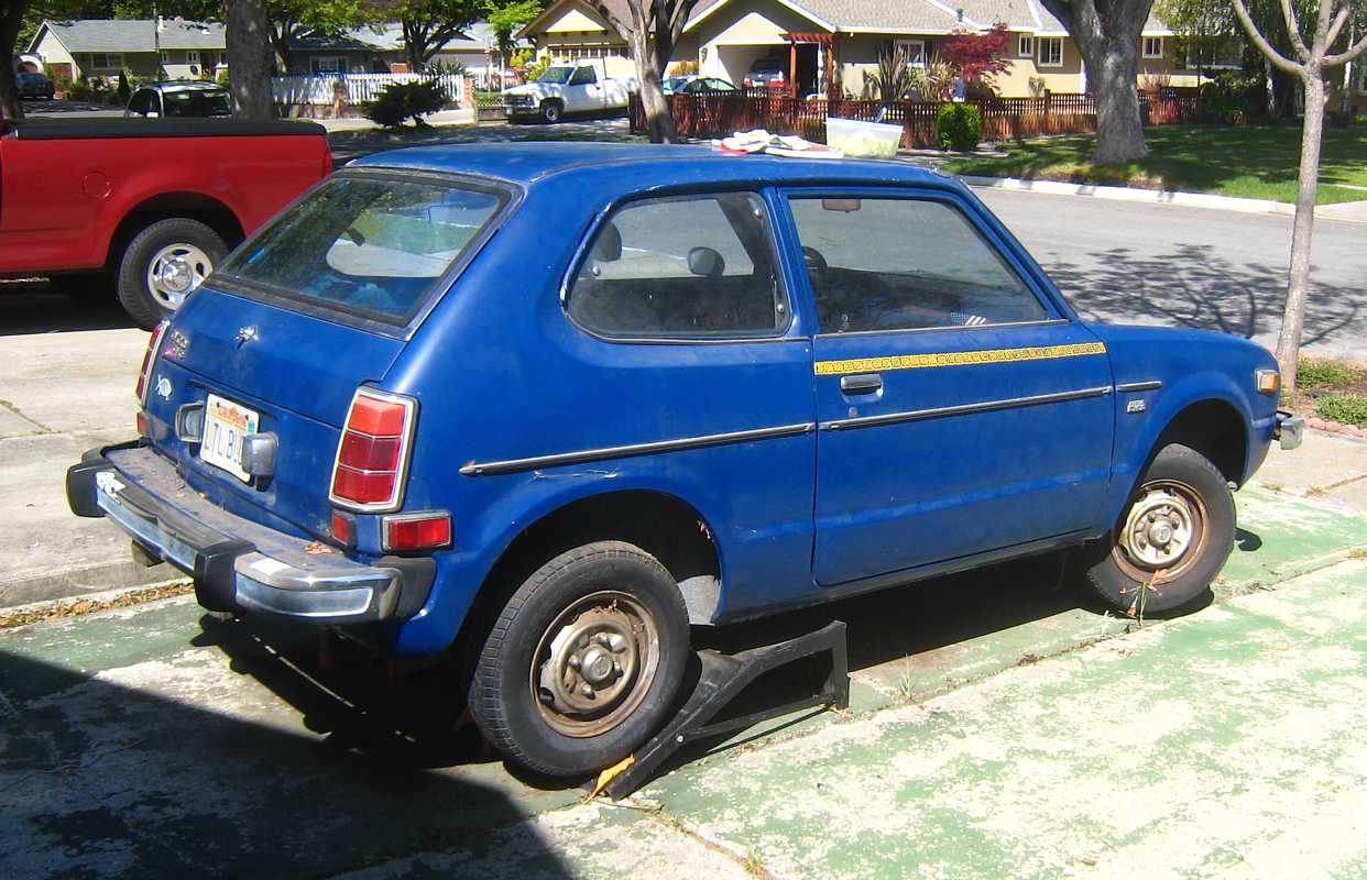
| Once upon a time ( 1975 ) our family needed another car to supplement the faithful Dodge Dart. A 1976 Honda CVCC was chosen to do the task. Soon, the car was called "LTL-BLOO" :-)) It was a real sweetie :-)) |

|
Table of Contents:
- Introduction - 1975
- Remove the gasoline engine - April 14, 2012
- The electric motor and controller
- Painting the Engine Compartment
- Intermittent Electric Honda Newsletter (#1) - July 31, 2013
- Attempt Install Motor Transmission - Aug 17, 2013
- Adjust Clutch Linkage - Nov 17, 2013
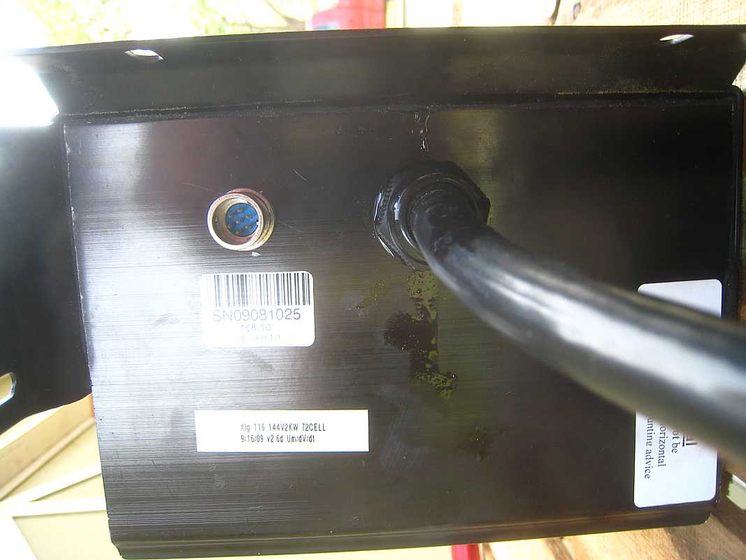
- Introducing the Battery Charger - March 9, 2014
- Moving (well - OK, Towing) Day - Oct 11, 2014
- Operational :-)) - Sept 2015
- The Gas/Battery Gauge - Dec 2015
- A MOSFET to replace the Tank Sensor - Jan 2016
- publicity, (local copy)
Why choose this car? - 1975
In 1992, the kids were mostly in college and was it the empty nest syndrome or other, the nuclear family no longer lived together.
After some study, and visits to the San Jose Electric Auto Association (SJEAA), Carl decided to give it a try. The basic plan is to:
|
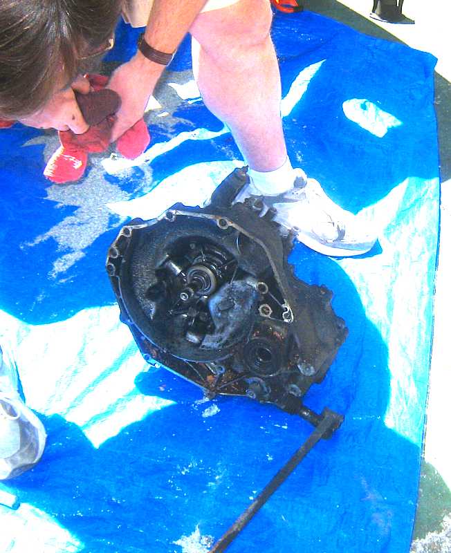
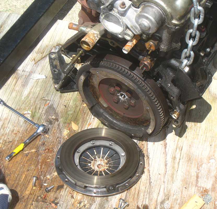
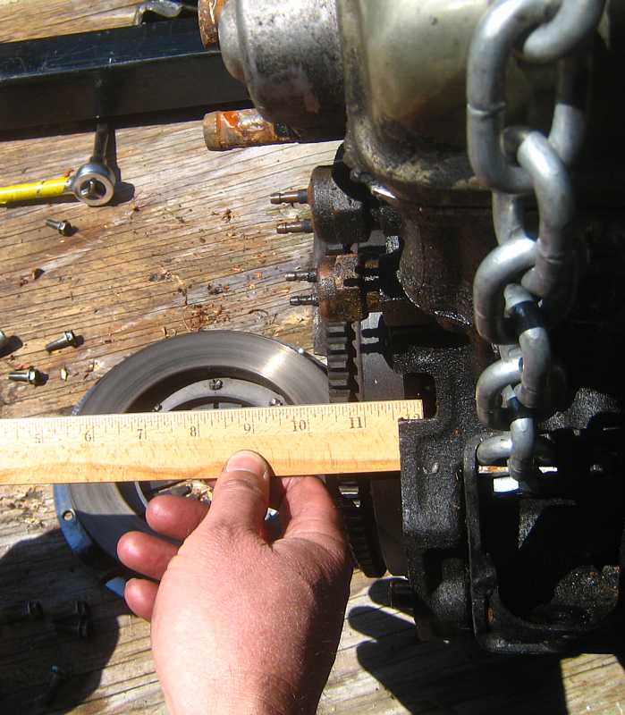
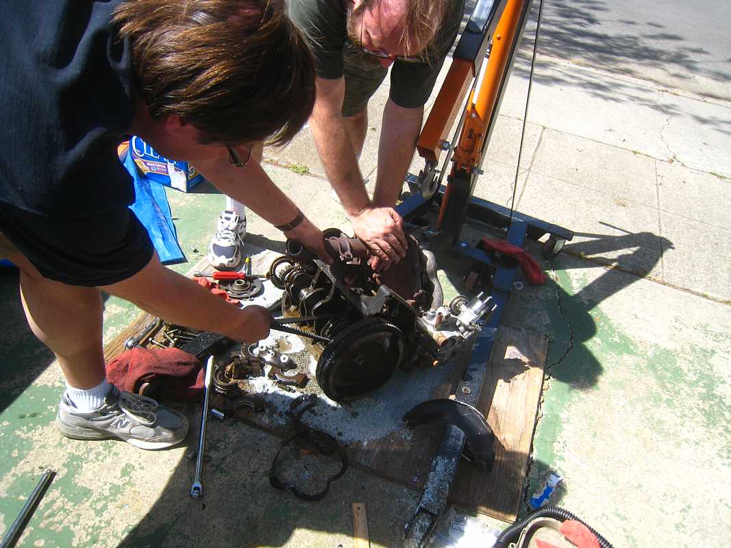
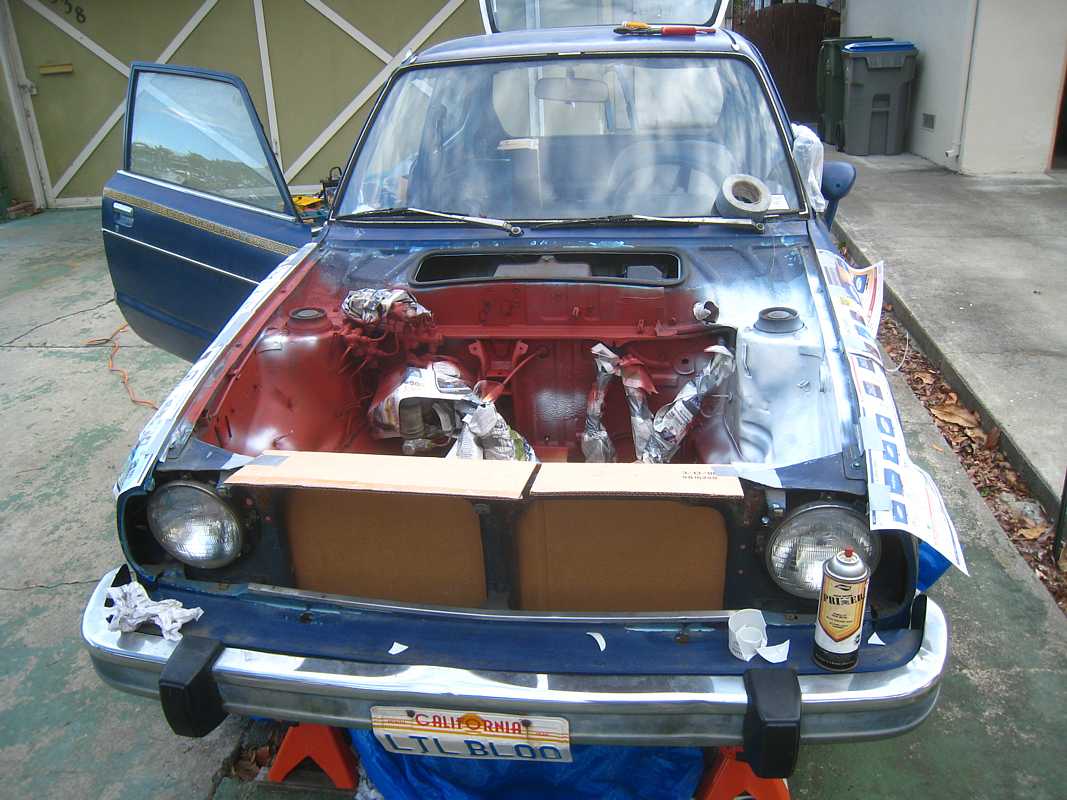
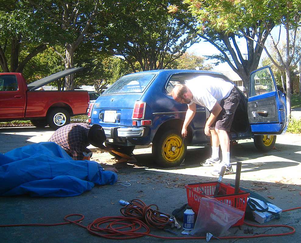
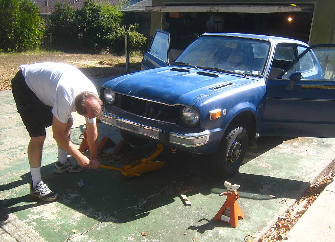
Remove the gasoline engine - April 14, 2012
|
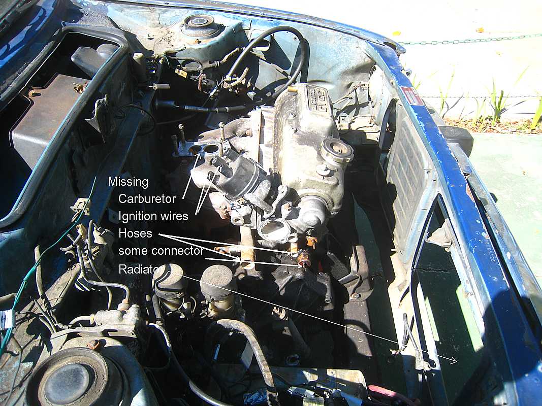
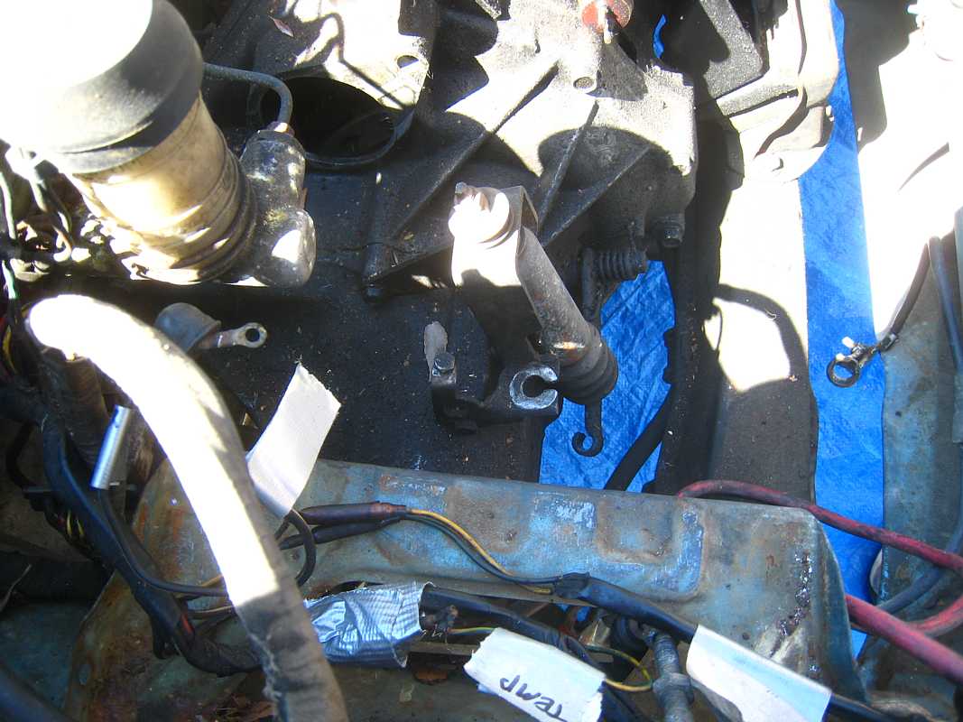
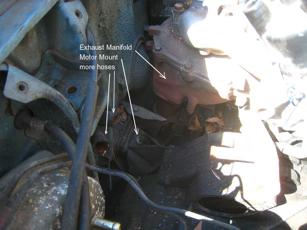
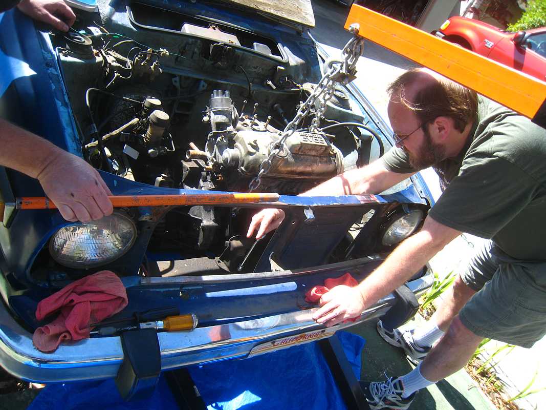
The following pictures show is just one stage of the conversion to electric -
Carl has already accomplished :
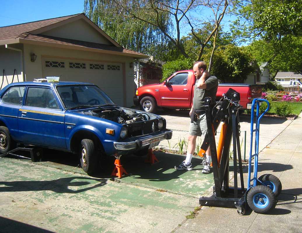
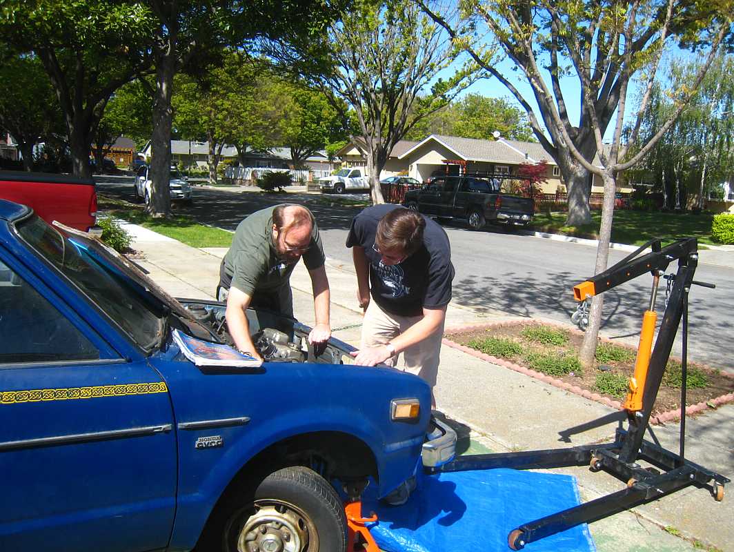
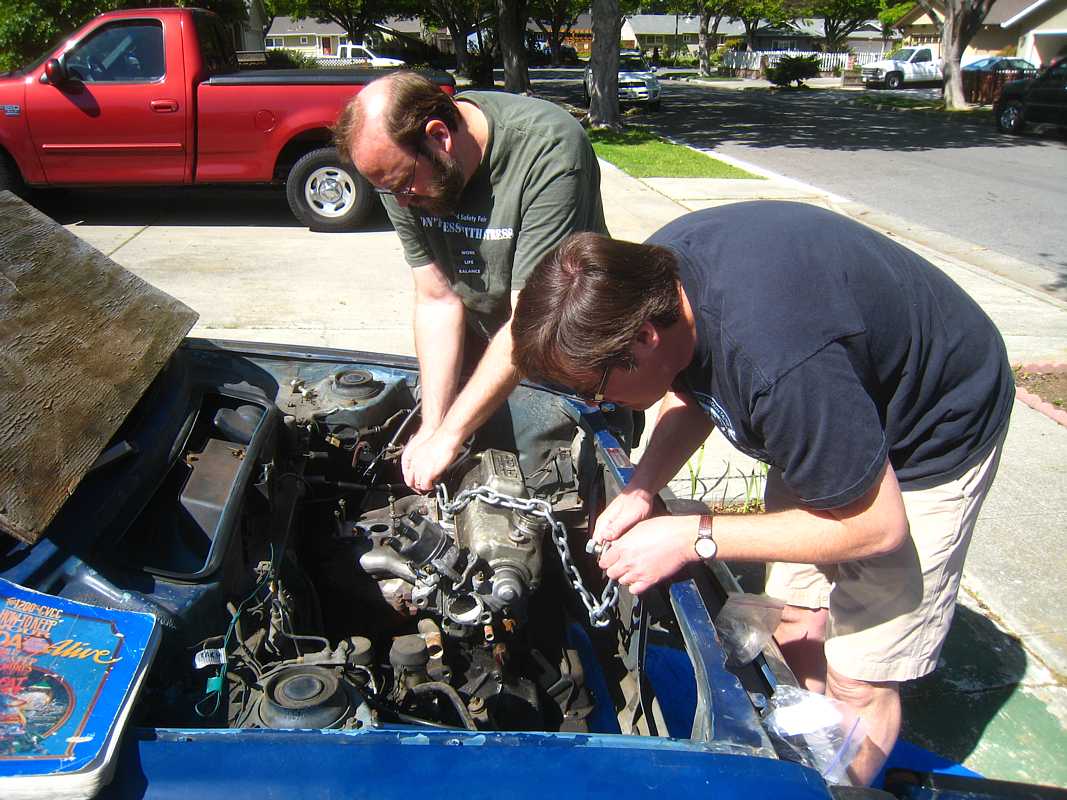
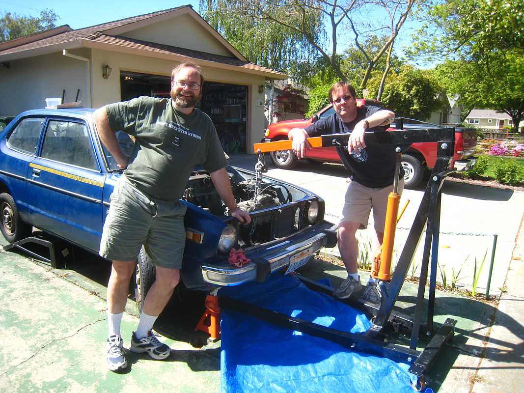
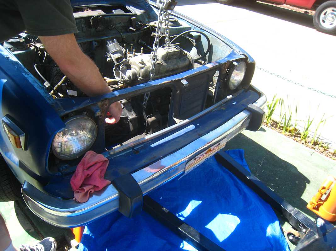
OH, and how could I forget the engine hoist from Randy's neighbor, who just happens to race his cars on weekends for a hobby. I think we got this heavy awkward thing from Randy's house to Edward's house in Randy's van. A real struggle, but no crushed fingers :-))
So - the results for the days activities
|


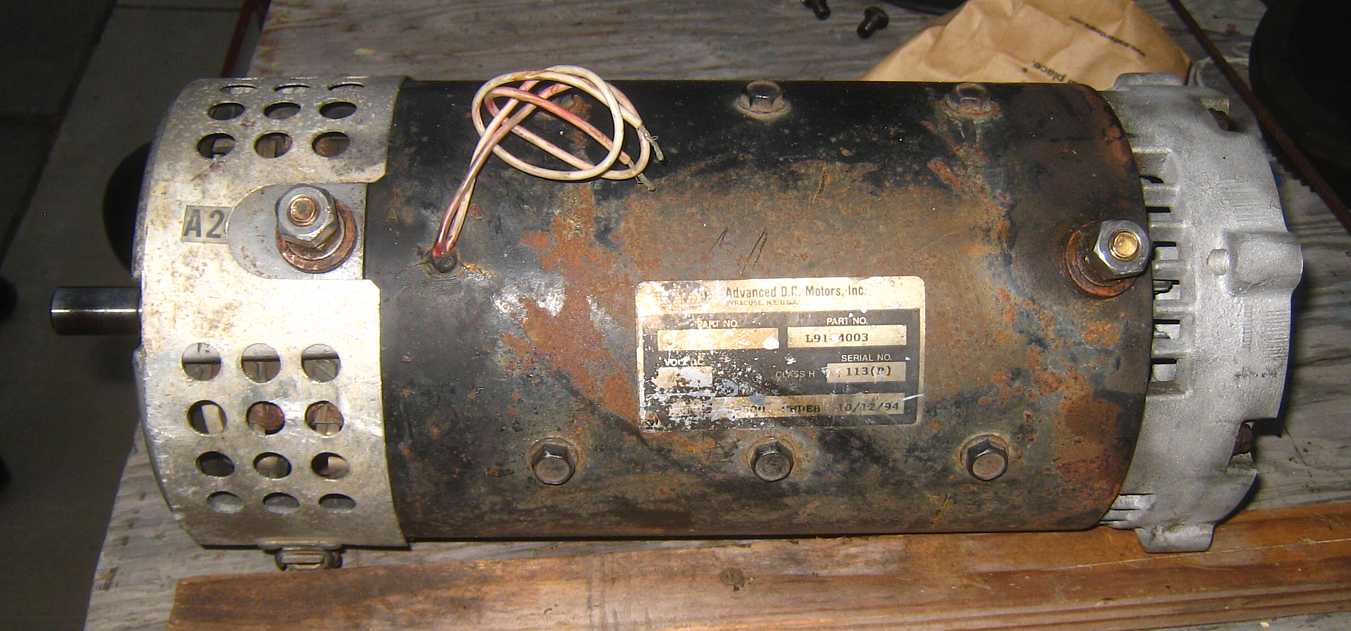
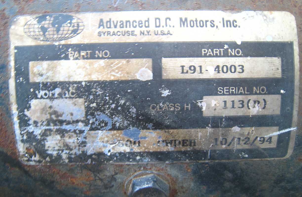
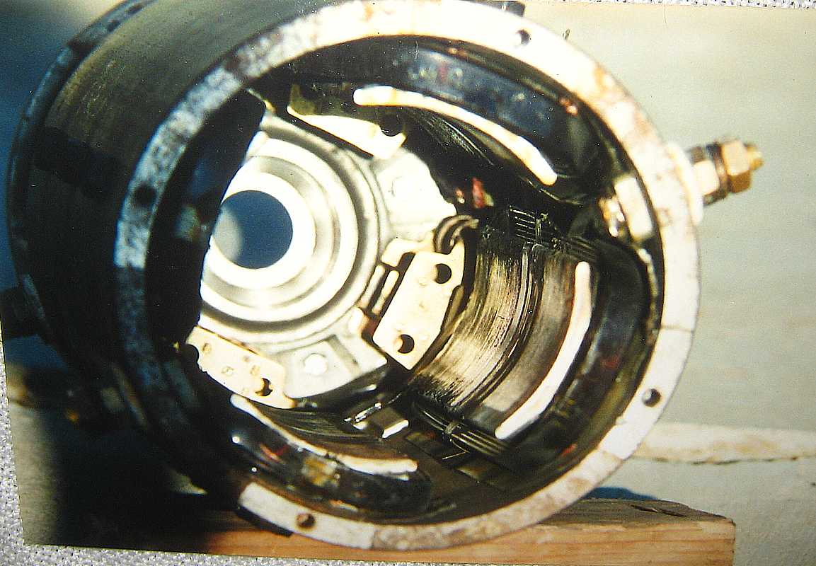
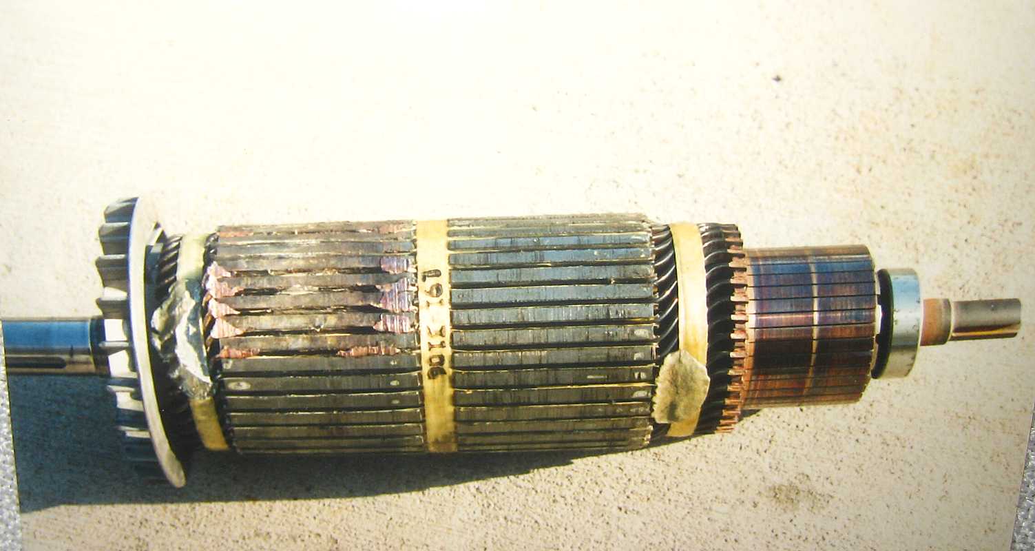
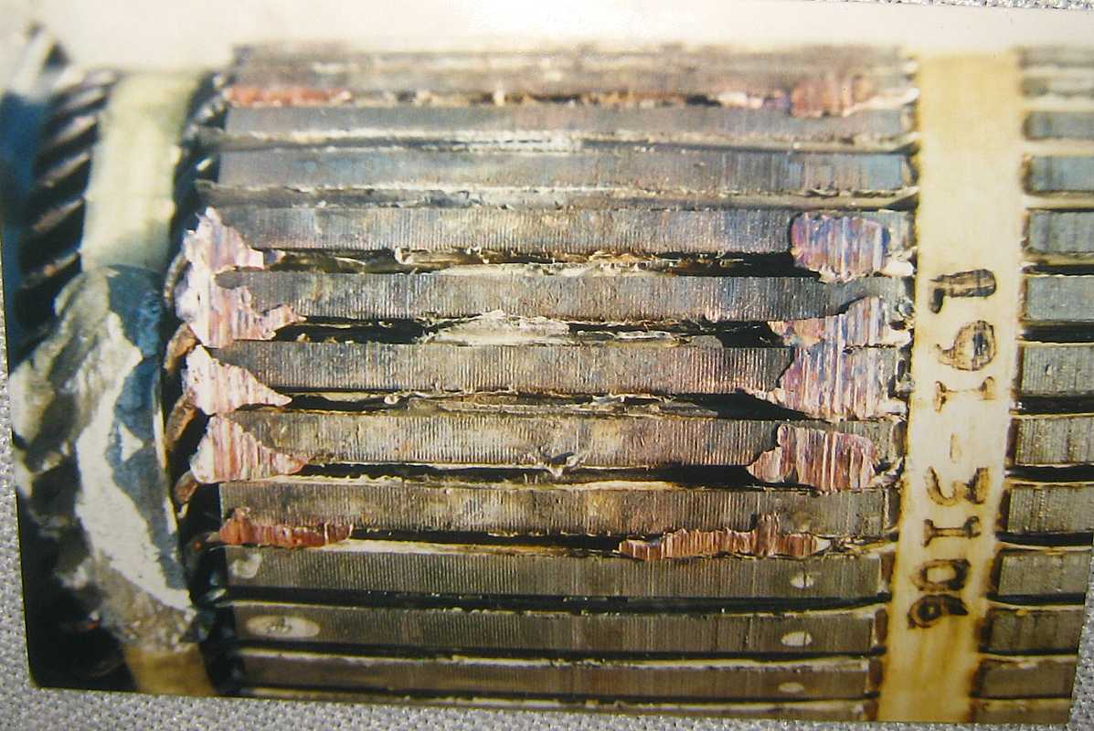
The electric motor and controller
|
So, August 11, 2012, Edward and Dad (me) found ourselves at Carl's house
after a wild movie called "The Avengers" :-| Of course we needed
to see Carl's latest toys - like the electric motor and the motor controller
for the recycled Honda CVCC.
|

Painting the Engine Compartment
|
It is March 30, 2013 - time to paint the engine compartment - Carl wants to
apply primer to avoid having to steam clean the area.
|

Intermittent Electric Honda Newsletter (#1)
- July 31, 2013
Carl Thelen to ...
|
At long last, the trickiest part of the whole operation is complete!
It�s the mating of the motor and transmission through the adapter
plate. I can put them together and take them apart with little effort,
and it seems as if the clutch works properly. The company in Santa
Cruz that did most of the work did OK, but didn�t test it. As an
engineer, I think it�s important to do component testing, especially of
important and complicated parts. So testing took a while, and it
tested good, and I learned a thing or two about transmissions and
clutches.
I have decided to paint the interior metal work in the engine compartment the same color as the existing interior, which is the car�s original color, �Highland Blue.� After clearing out the engine compartment, I cleaned the grease and gunk out of it, prepped for painting, and started to put on a primer coat. The first spray can of primer stopped working for some reason -- there was still stuff in the can, but I couldn�t get it out. It was red primer. Fortunately, I had another can of primer - white - and I used that until _it_ ran out. Fortunately, a neighbor had some - gray this time - and I finished the job with that. So the primer inside the engine compartment is about 50% red, 40% gray, and 10% white. Wow! I learned something about automotive spray paint. See, back in the days you painted the car, with a few coats so it would last. These days you paint it with a thin coat of paint, called base coat, and cover that with �clear coat,� which makes it glossy. This process is cheaper, since the expensive part of paint is the pigment, and clear coat hasn�t got any pigment -- it just protects what�s there. This base / clear process is called double stage. If you want the color and clear coat in one can - called single stage - you still can, but you have to use it within 24 hours of opening the can.
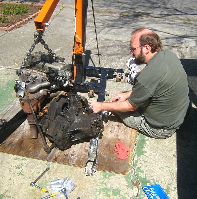
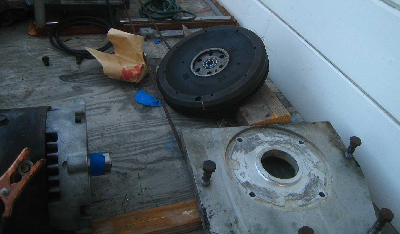
So, the next step is to mount the motor and transmission into the engine compartment. This is going to be an interesting process, as I�ll probably have to fabricate new motor mounts. But it will work eventually. I have to install the motor and transmission before making the battery boxes, because how they end up will affect how many batteries I can put inside the engine compartment. It�ll almost certainly be either 3 or 4 -- 3 is a bit less weight than was removed, 4 is a bit more. But I kinda need to know that before I finalize the battery arrangement in the rest of the car. Attached is a picture of the painted motor and transmission. Motor is in foreground, but you already knew that, right? Cheers!
Carl Thelen
|

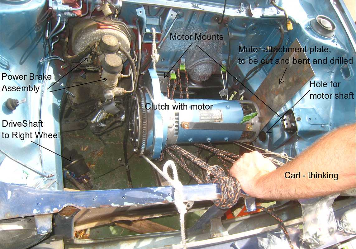
Attempt to Install Motor & Transmission - Aug 17, 2013
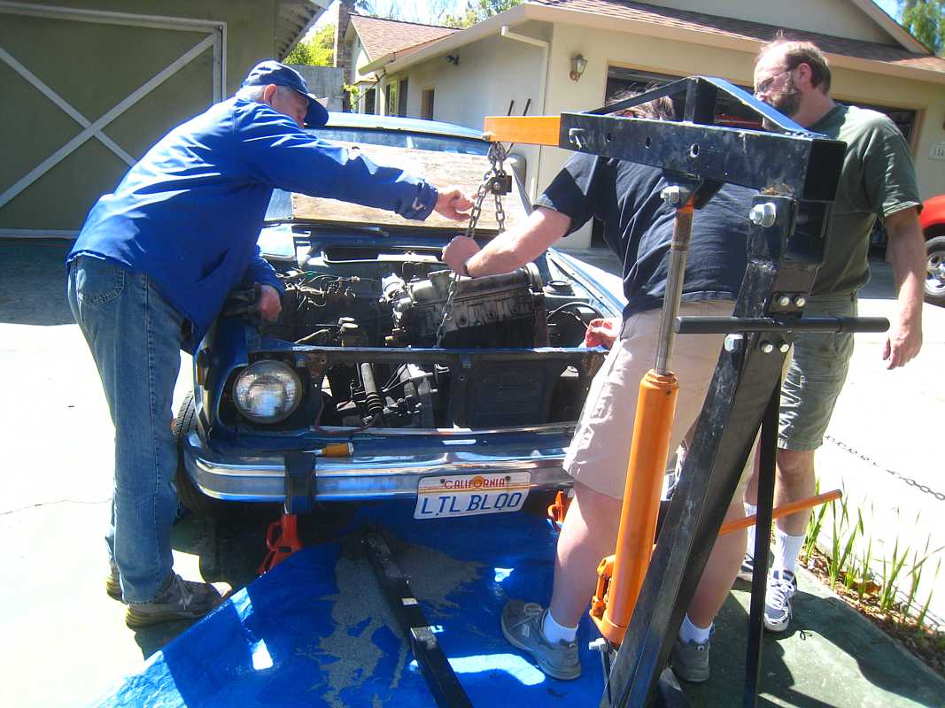
 Carl & Dad tried to install the
- electric motor w attached clutch - transmission-transaxle - "engine mounts" into the "engine compartment" without the use of an engine hoist. You notice ropes stretched across the the engine compartment to support the heavy electric motor w attached clutch. The supporting ropes could be adjusted in length to raise/lower/tip the heavy load. (Carl & Dad can barely lower the thing into the compartment without medical damage. Attempts to mate the transmission-transaxle with the clutch while in the engine compartment were unsuccessful, frustrated in part by the protruding power brake assembly which we did not wish to disturb. At noon, Randy, Mason & Art brought pizza and good cheer - and went with us to the store to get correct length bolts - our attempts to cut the proposed bolts with a saber-saw being unsuccessful. Next time, mate the motor with transmission on "work bench" and install using an engine hoist !! |
Adjust Clutch Linkage - Nov 17, 2013
|
Its been a while since I visited the exercise. Carl's week ends and mine seemed to clash -
You may note that the motor and transmission are installed. Carl assures me that he used an engine hoist ;-))
Then Carl tried to re-install the final the driver's side wheel linkage - removed to install the motor - that did not go as planned !! It was time for me to leave to escort some IBM-1401 VIPs - former project manager and engineering manager, even older that I !! |

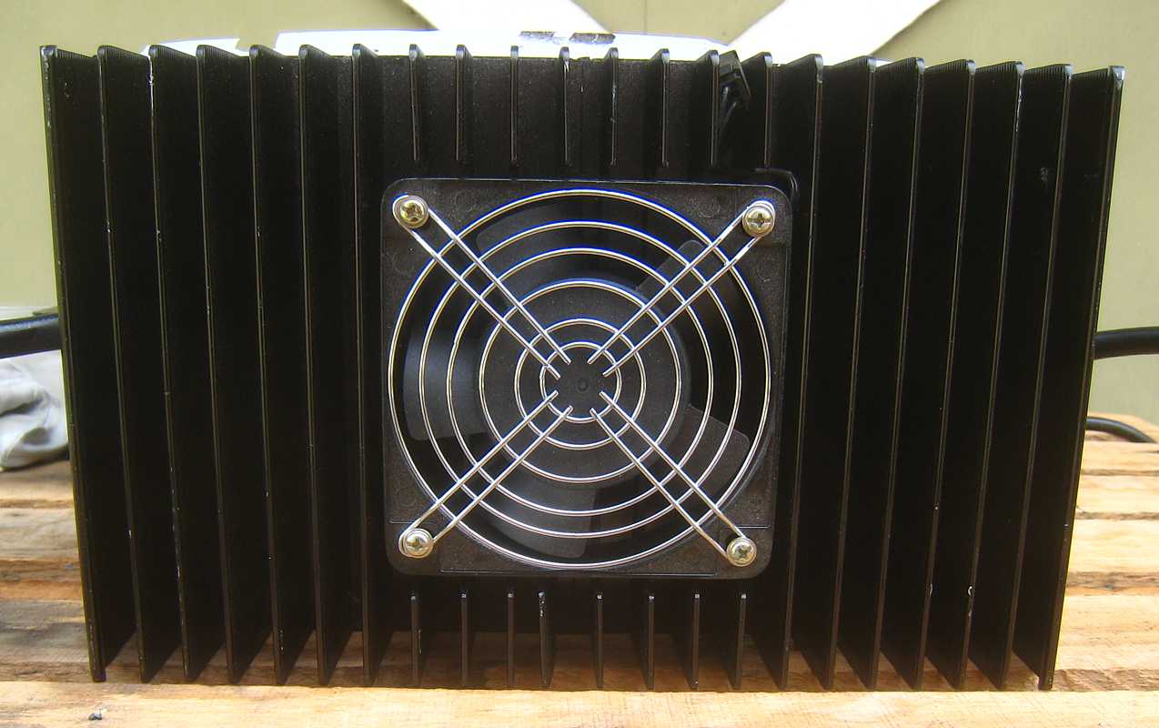
Introducing the Battery Charger - March 9, 2014
|
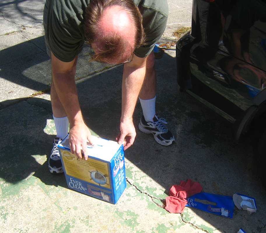
So - we went back today to test the fit of a battery box that Carl has tack welded from 1"x1" angle iron.
(We had previously cut and taped and stapled a cardboard box of the same identical dimensions
to assure the fit and the ability to get the box into a rectangular hole cut in the floor of the trunk -
basically occupying the volume previously occupied by the gas tank. The angle iron box fit just fine,
after as slight adjustment with the "kinetic persuader" ( a carpenter's hammer ;-))
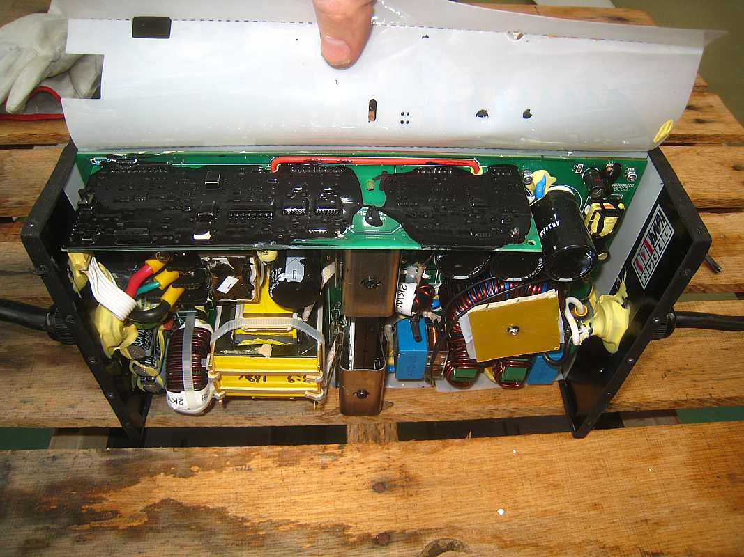
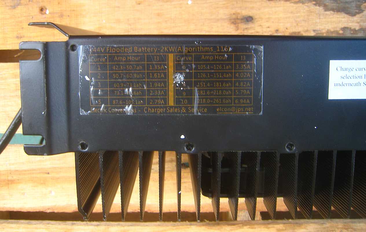
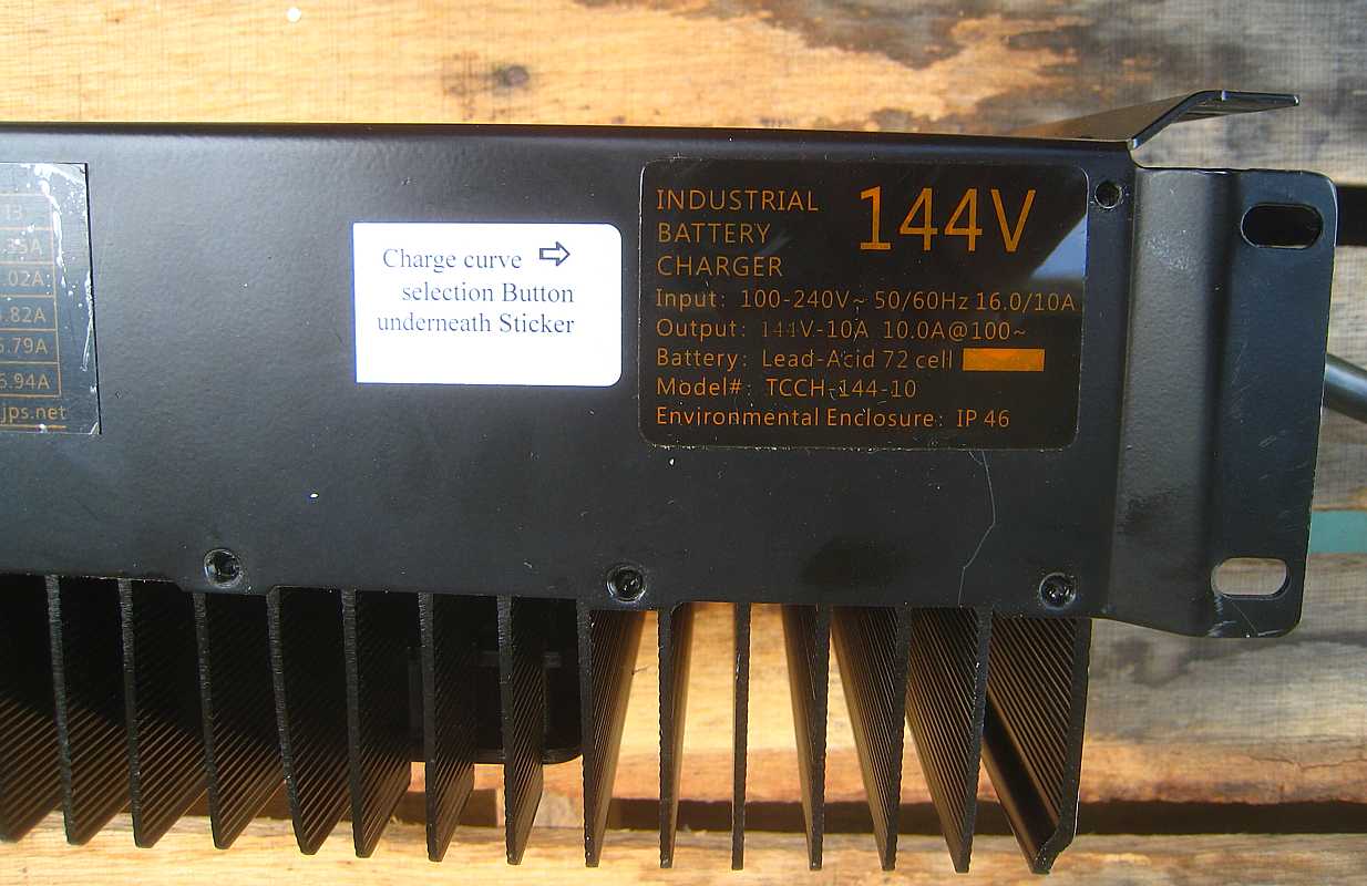
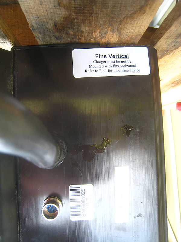
Carl also brought along a second hand battery charger he had purchased to see if it could be installed in the rear adjacent to the rear battery box. (One must specify which battery box - they will be all over the car.)
http://www.elconchargers.com
What are the LED error messages on a Elcon PFC charger?
If there is an error condition and the charger is not charging, it will repeatedly display one of the following error messages on the Red-Green LED. The dash stands for one second.
|


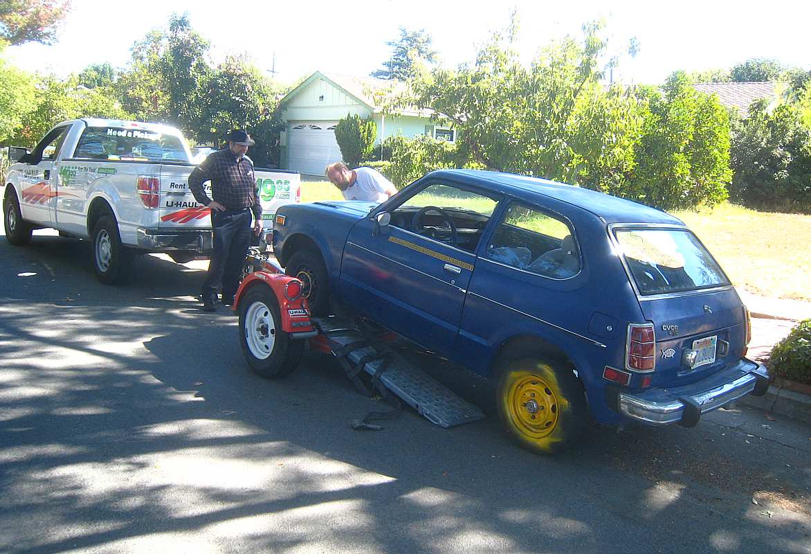
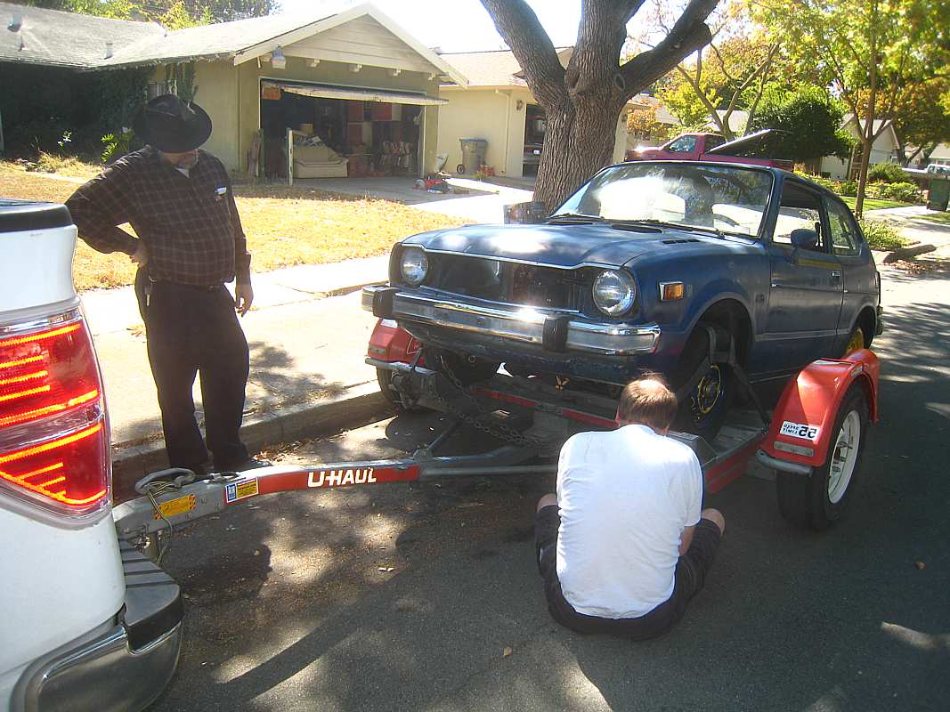
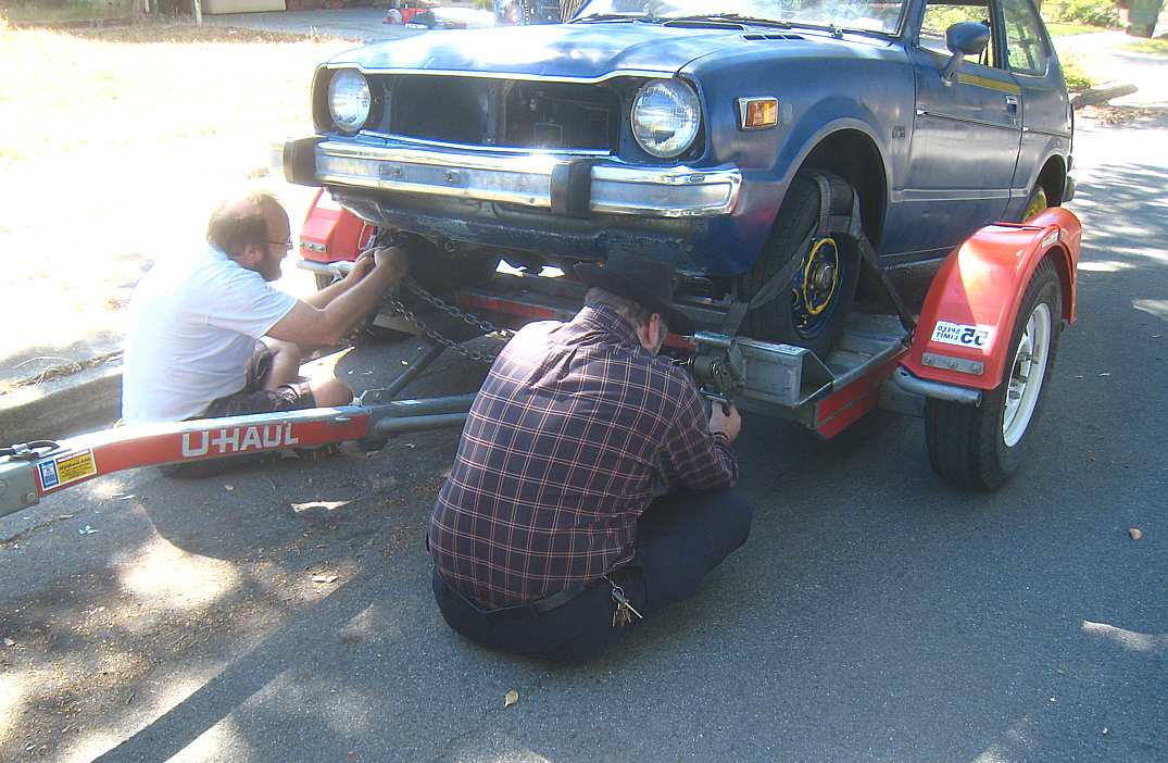
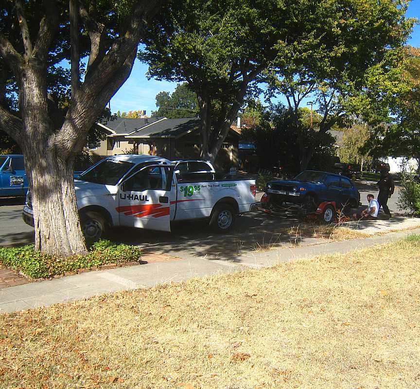
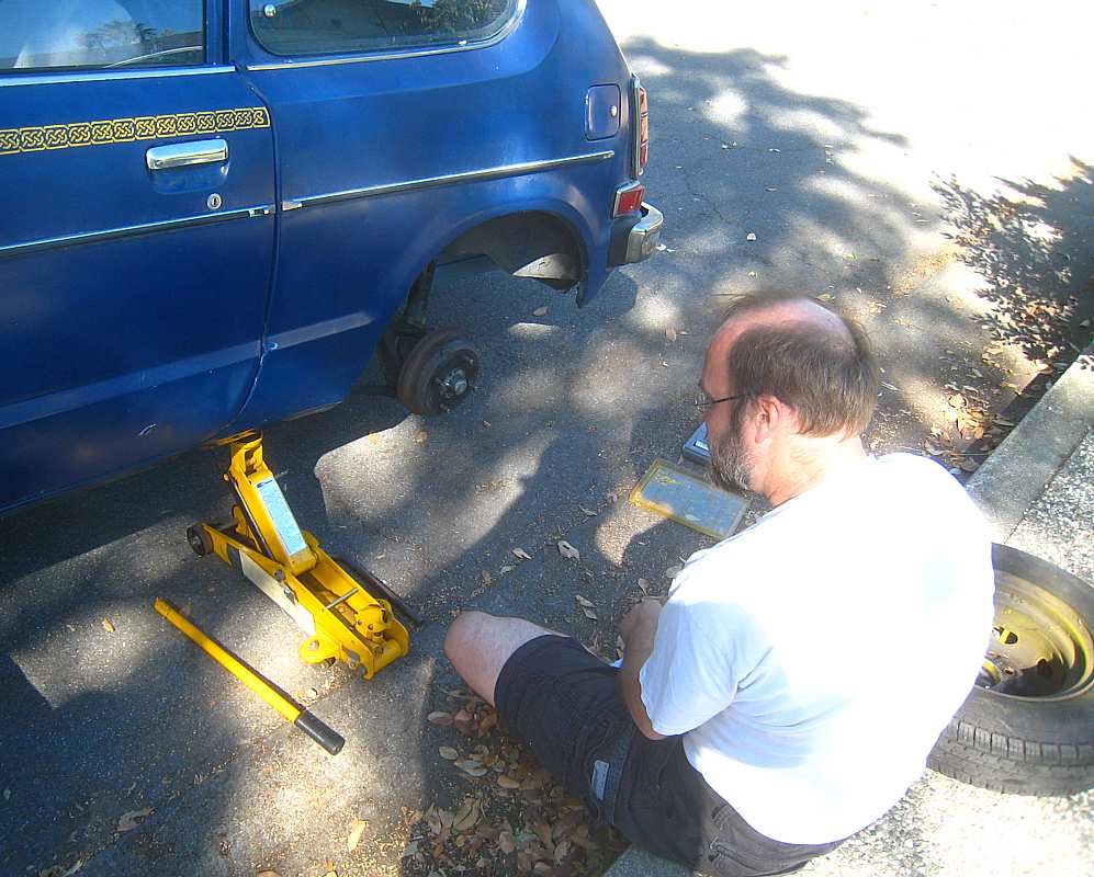
Moving (well - OK, Towing) Day - Oct 11, 2014
| Since the last report,
- battery boxes have been painted, checked for size, installed, - stiffer rear springs with internal shock absorbers installed, - parking brake cable re-routed, had gone over gas tank - hood re-installed, various dangling wires and cables secured for towing -
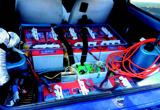
Not wishing to be responsible for man-slaughter, Edward and I suggested she spend the money for a licensed electrician! In any case, I have no idea what another neighbor (Bob) and Carl did to the left rear bearing nut (which I claimed was too tight) and the dragging brake assembly. By the time I got back from the home brew (or stew) electrical question the car was ready to tow. The next test tow was "cool" ;-) so Carl drove the truck towing the car, and I played tail gunner to make sure no smoke or other debris left the towed car. We arrived at Carl's house and Mary Ellin was the driver as Carl and I rocked the car out of the towing dolly and into Carl's driveway :-)) Happiness - no fingers have been lost/smashed in this exercise so far :-))) Carl needs to install a 12 volt system for car wiring such as horn, lights, radio, ... Then install the 170 volts of propulsion batteries, assure parking brake works reliably, likely remove the "differential" in the hydraulic brake system as the weight distribution will be very different - a heavier rear - and somehow get street legal. Good Luck to us all :-))) |

|
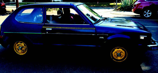
We have been hearing reports that the car is functional. On a visit to Carl's house
in August 2015, Carl gave each person a ride around the neighborhood in his electric car.
The rides were moderate - no attempt to go 0 to 60 mph in a second ;-))
Instead of some engine noise, we heard transmission gear and road noise.
(Since the car is now a "2 Seater", there were a number of trips.)
(I forgot to take pictures and also to inquire about street legality.)
September 2015 - Coming back from "Wings Over Wine Country" I took these pictures
|
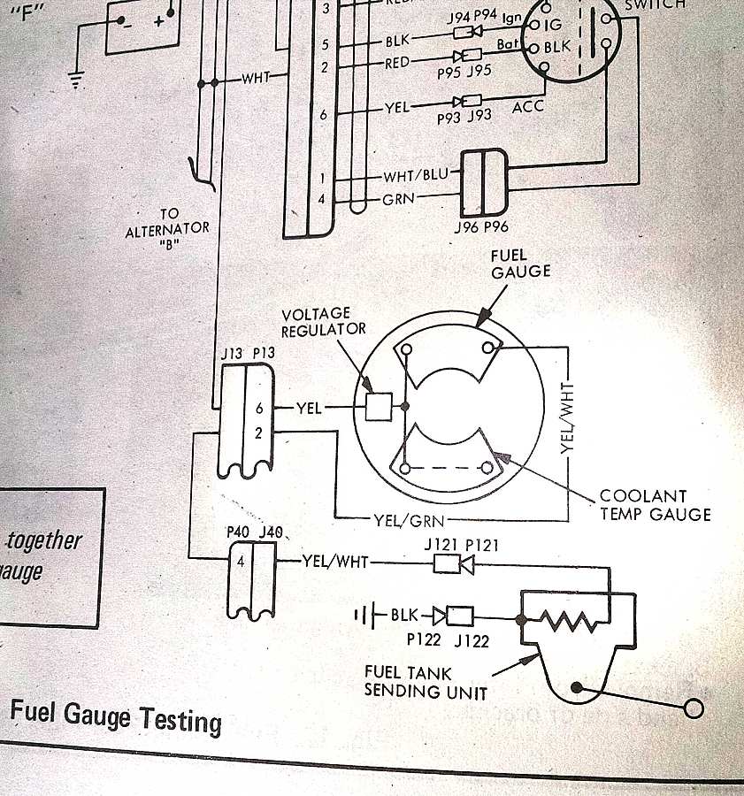
The Gas/Battery Gauge - Dec 2015
Carl would like to show his voltage based state of battery charge on the little Honda's
fuel gauge.
But it does make measuring the propulsion voltages "interesting" with a gas gauge with an apparent hard wired voltage regulator with a chassis ground reference.
So - Call in the experts,
Stan Paddock suggested using a "linear opto isolator" on the propulsion side
to indicate the voltage to the grounded side.
What irritates me no end is that I like Stan's idea better :-((
I forgot to mention that Ron Crane suggested alternatives to estimate the energy remaining in the battery - some comments added ;-))
like in the ?good old days? people used hydrometers to estimate specific gravity of the battery acid and ??remaining energy??
Trying to get a handle on the characteristics of the voltage regulator and meter in the Honda schematic (above) I asked Carl to measure the electrical connections of the wire at P121 or wire 4 at P40 - the one that goes to the gas tank sensor. - Both tests with normal dash voltage present - about 12 volts
Carl replied that
Maybe there is a lot more in that "Voltage Regulator" than I imagined -
........... and voltage controlled resistors seem to be in the 10k ohm resistance range rather than the 0-100 ohm range :-(( |


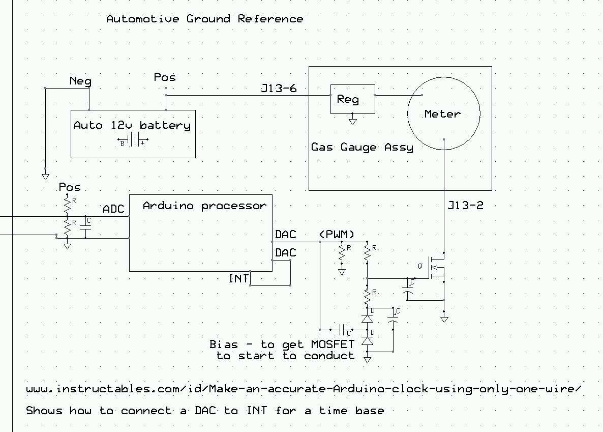
MOSFET to replace the Tank Sensor - Jan 2016
That pulsing of the current to the Tank Sensor (above)
seems to need low ohmage voltage controlled resistor.
|
A Real DIY ProjectSaint Mary's employee designs his own electric car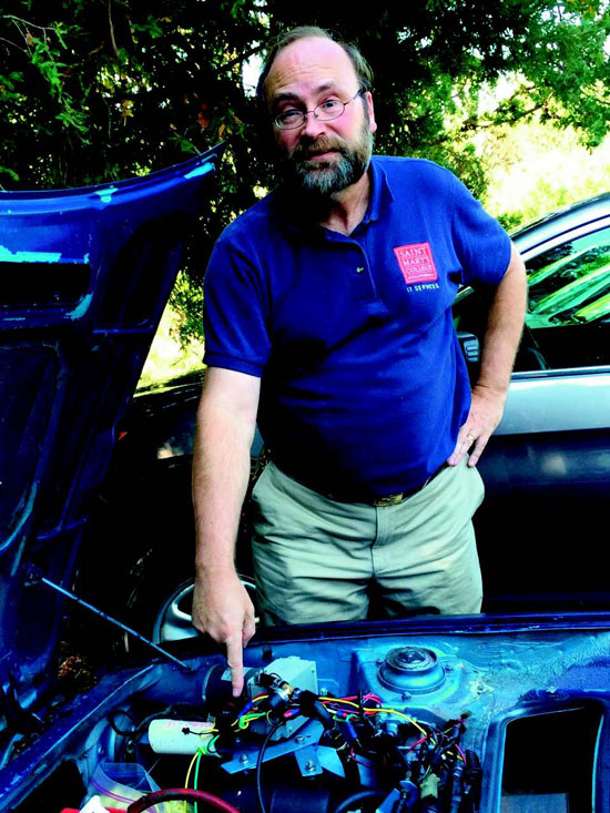
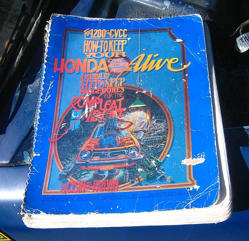
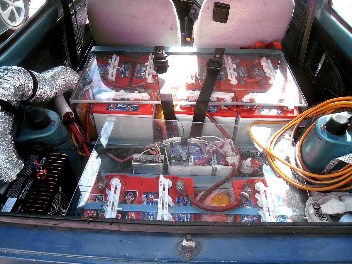
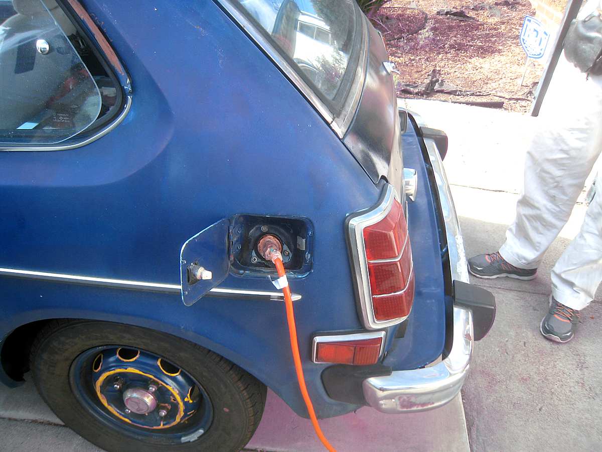
Carl Thelen points out the wiring under the hood Photos Diane Claytor When Carl Thelen graduated from UC Berkeley almost 30 years ago, his family gave him a graduation gift: their 10-year-old manual transmission Honda Civic. He was thrilled. For the next 20 years, it was his daily mode of transportation. "It was such a fun car to drive," said Thelen, who is the director of instructional technology at Saint Mary's College. But then it developed "the bad - and very expensive - habit of blowing head gaskets," he noted. The car sat, unused, for several years. He couldn't find a replacement engine. His auto mechanic tried rebuilding the engine, but the head gaskets kept blowing. So Thelen, who said he was "fortunate enough to go to school at a time when they still taught metal shop, wood shop and electronics," came up with the bright idea to try converting his 1976 car, which had 276,000 miles on it, to an electric vehicle. "I figured I had learned all this stuff years earlier so I could do it," he said. A self-described tinkerer, Thelen admits he had no idea where to begin. He went to a local electric car club and learned that the Civic is an excellent car to convert because it's small, lightweight and strong. He talked to people, read books and slowly moved forward. Of course, like most projects, this one took far longer and was considerably more involved than expected. The "very part-time" conversion started in 2010; with the help of his 10-year-old daughter, it is now mostly completed. "At least it's finished enough to be considered legal, with all the proper stickers," he proclaimed. The car uses 15 eight volt lead acid golf cart batteries (a 120 volt system): 11 in the back, four more in the front engine compartment; 120 volt cables; and a 12 volt auxiliary battery that basically does the same thing as the starter in a regular car. The engine and miscellaneous items were removed and approximately 1,200 pounds of batteries and other items were added. So this electric vehicle now weighs about 600 pounds more than its pre-converted model. A can of "fix a flat" has replaced the spare tire "to keep the weight down," he said. "The books I read said to have a fire extinguisher on hand. I'm not sure why, but I have one." There is also a circuit breaker that will shut everything down if something goes wrong. While not thoroughly tested, when fully charged, the car has a range of about 43 miles, depending on the number of stops, hills, speed, and temperature, Thelen said. "I've calculated that I can go from home in San Pablo, take my daughter to school, get to work and then, if my daughter got sick, get back to her school and home again," he said. Of course, by then, the battery would be "completely exhausted." There is a charging port - a 120-volt, grounded plug - where the gas tank opening used to be. And Thelen knows - and has used - just about every parking spot on campus that's near an outlet. He fully charges the car at home every night; it takes about 15 hours. "So I'm really not limited to 43 miles during the day," Thelen noted. "I just have to be near an outlet and have the time to charge it. It's typically fully charged again by the time I leave work. It really is the perfect commuter car." Thelen also has a gas-driven car. "I drove it last week and by the time I got home, it was pretty much 'sucking fumes.' I'm no longer accustomed to looking at the gauge on a regular basis." As for speed, Thelen said he's gotten up to 75 miles per hour. "But it's not very happy going that fast. That speed really drains the battery. It's very happy at 60 miles per hour. In first gear, it cruises along at 25 miles per hour; in second gear, it's a happy camper at 40 miles per hour." Before going for a quick ride, Thelen, a very animated speaker, described all the sounds his passenger may hear. "There are going to be some strange noises," he explained. "The doors creak, there will be a funny noise from the vacuum pump, a clicking from the contactor (main switch), whirring from the motor and squeaks and groans from the back." Every noise mentioned was, indeed, heard. The conversion likely cost between $5,000 to 7,000, Thelen said, "vastly more than the car is worth." And he's really not sure how much time he's spent on it over the past five years. But it doesn't matter. Thelen explained that he did this because he wanted to challenge himself, practice some of the skills he learned a long time ago and "just prove that I could. Also, it's still a really fun car to drive."
|