|
Other types include
- Fibre optic gyroscope - MEMS gyroscopes, a subset of Vibrating structure gyroscope |
as of August 6, 2021
|
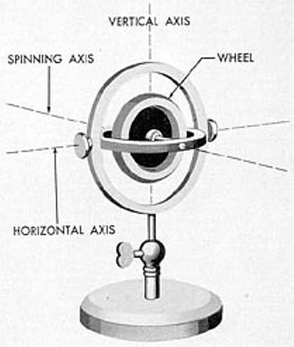
Most of us have been fascinated,
at least for a minute, by a child's "top" and/or a gyroscope. |
|

|
Table of Contents
- Introduction
- My experience
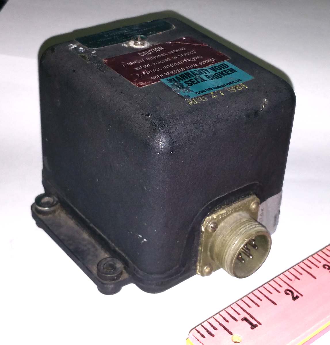
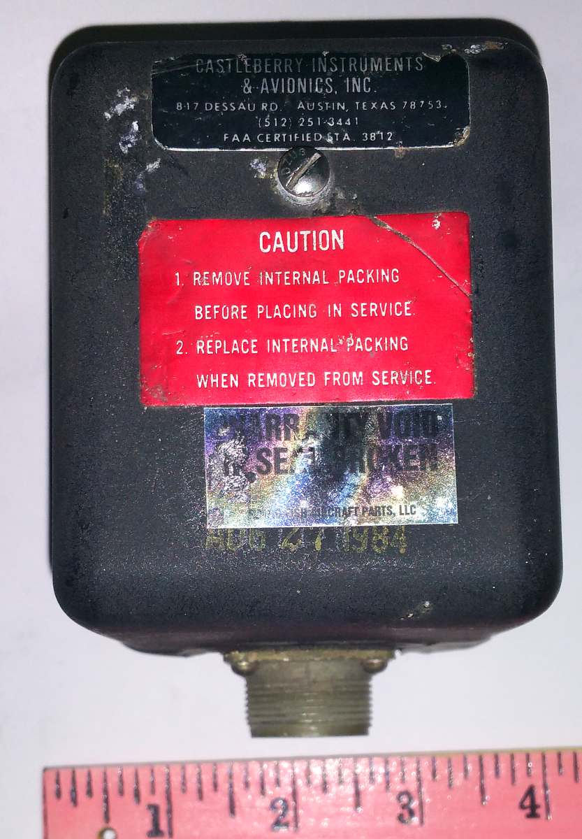
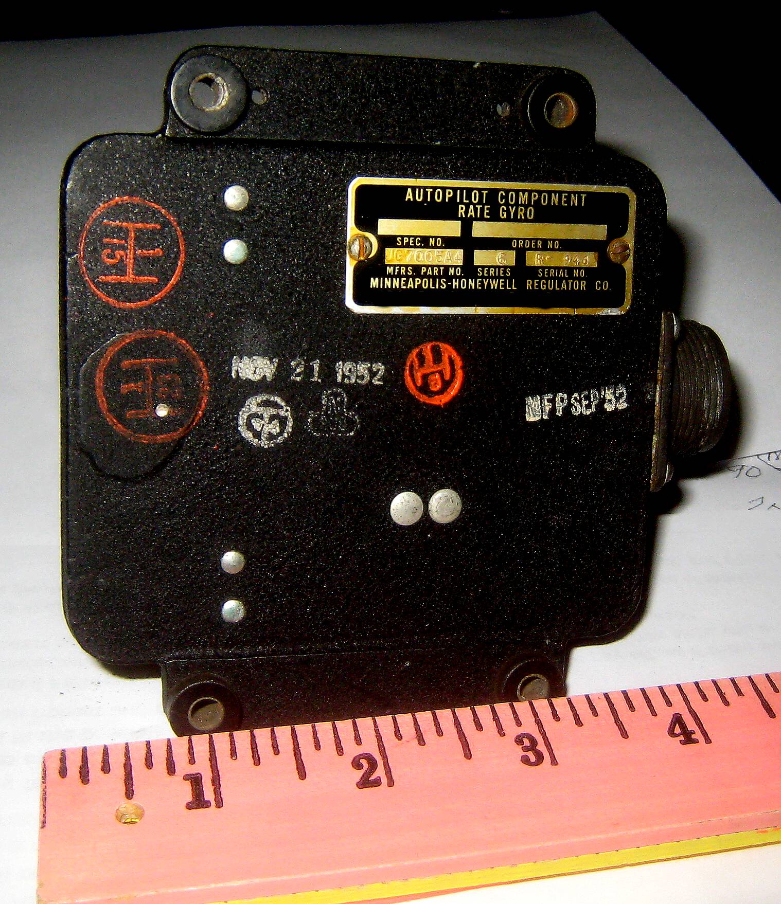
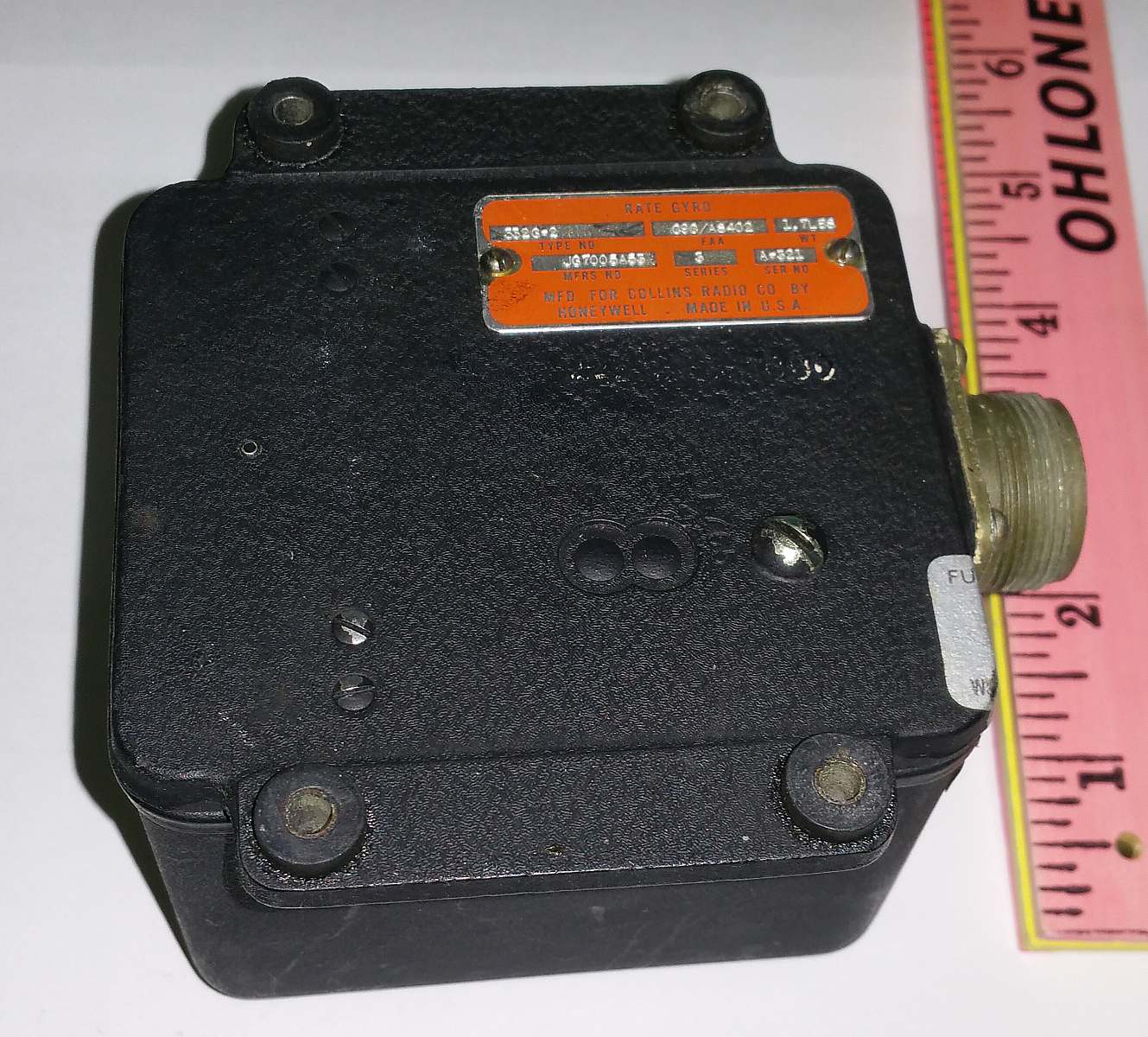
- "my" defunct 1952 rate gyro & a working purchase
- Vtg Aircraft Part SPERRY Directional GYRO Indicator TYPE C-5 Aviation gyroscope
- Humphreq Vertical Gyroscope Aircraft Helicoptor VM02-0110-1
- Interesting On-Line Manuals
- Saturn Guidance .doc
- from Charles Carter
- Temporary Other - Feb 2018
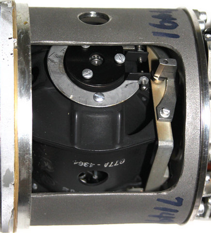
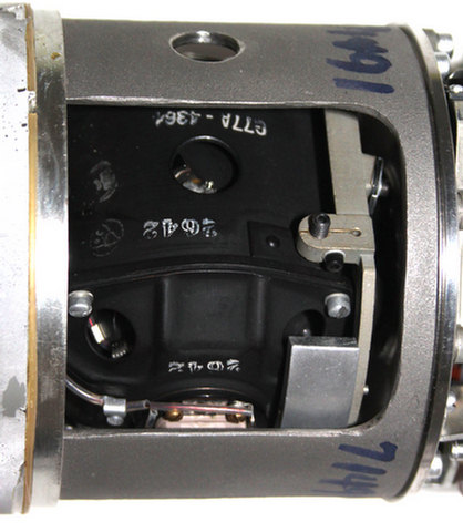
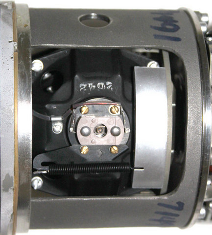
- Minuteman ICBM guidance unit
- Apollo IRIG Gyroscope, by CuriousMarc
-
The A4 / V2 rocket in detail: Bringing a V2 rocket gyro back to life - YouTube
- Gyros & Stuff from Brooke Clarke < brooke @ pacific . net > Jul 23, 2019
- Commercial Usage - Jan 7, 2020
- Walter Lewin, Lect 24, Gyroscopes,
VERY NON-INTUITIVE
|
When the rotor isn't spinning, a gyro is just a floppy thing,
Odd that just making the rotor spin causes such a difference !!
"
8.01x - Lect 24 - Rolling Motion, Gyroscopes, VERY NON-INTUITIVE",
by Walter Lewin of MIT
|
|
In the Army, I was in the Nike antiaircraft missile program which used free and rate gyros
as part of the missile guidance control system. However, I was in the radar/guidance area,
not the missile area - so never physically saw the gyros.
After the Army, I considered myself a real techie hot shot,
and lucky enough got a job at Minneapolis Honeywell Aero Division
testing "HIG" and rate gyros. I can wave my hands and
kind of explain how those work,
eluded me. A friend is an ex-submarine electronic tech who was inpart responsible for maintaining a gyro compass,
The purpose of this page is to wave my hands some more A bit of a confusion - an aircraft "gyro compass" is frequently a free gyro which must be frequently preset to magnetic north. It is used to indicate "North" during turns and accelerations that cause magnetic compasses trouble. It is not self-aligning (using the earth's rotation) with true north in the sense of a marine gyro compass.
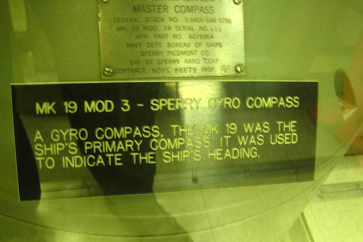
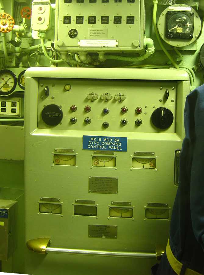
Pictures of the SperryRand MK-19 gyro compass installation in the Nautilis Submarine on exhibit at Groton, CT.
|
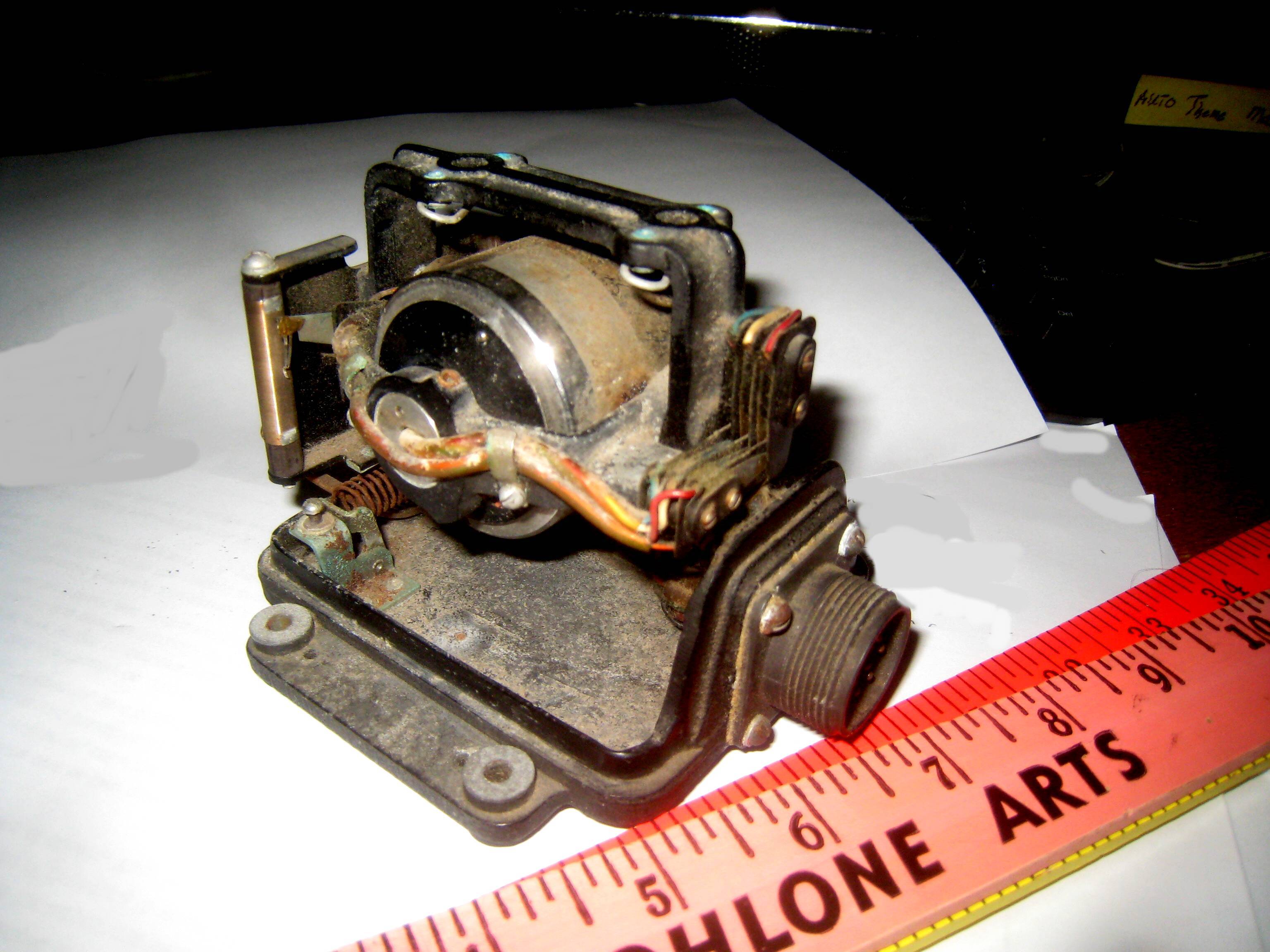
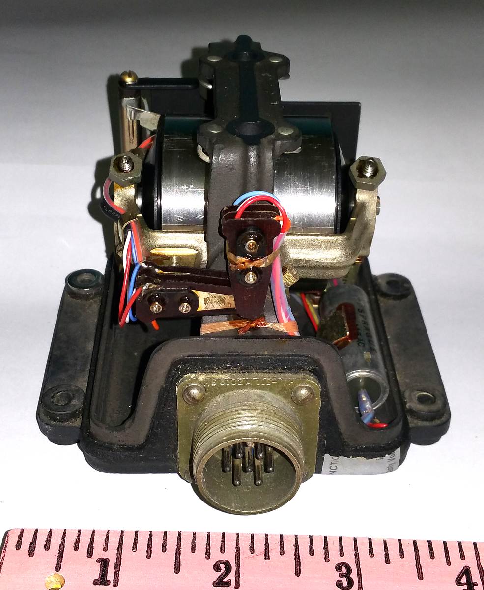
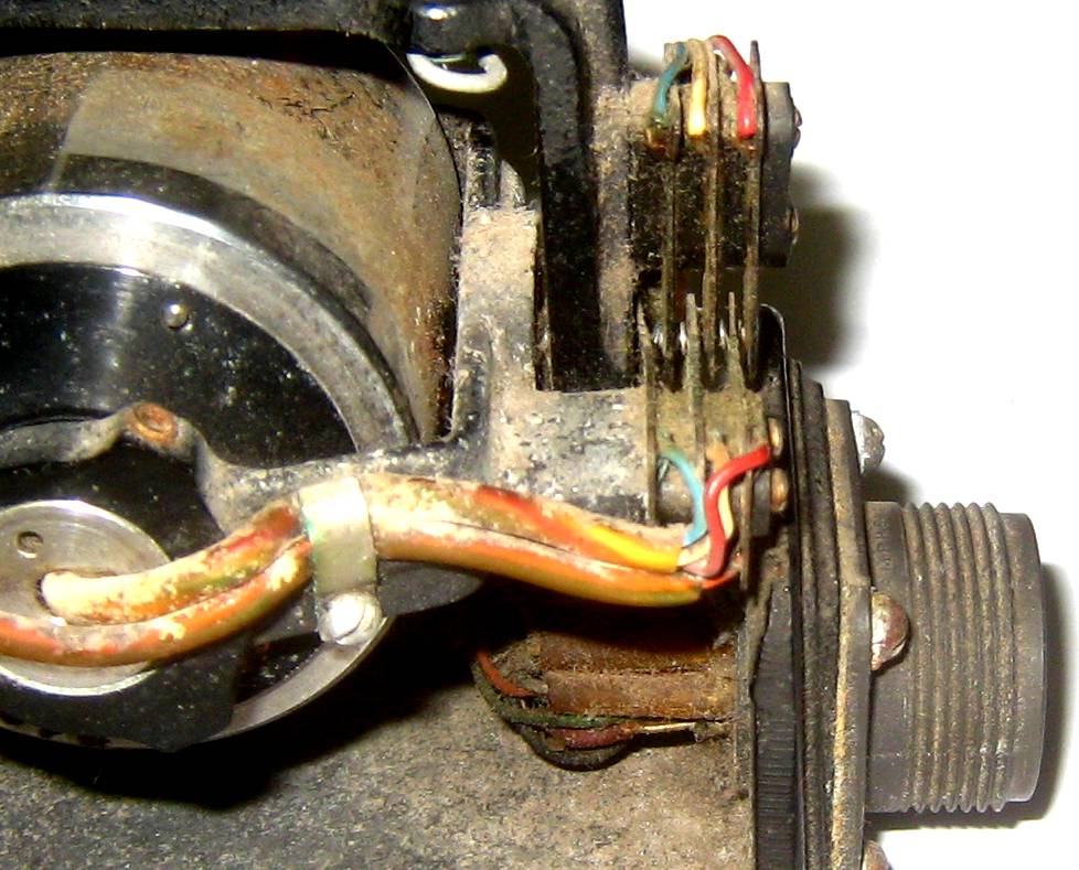
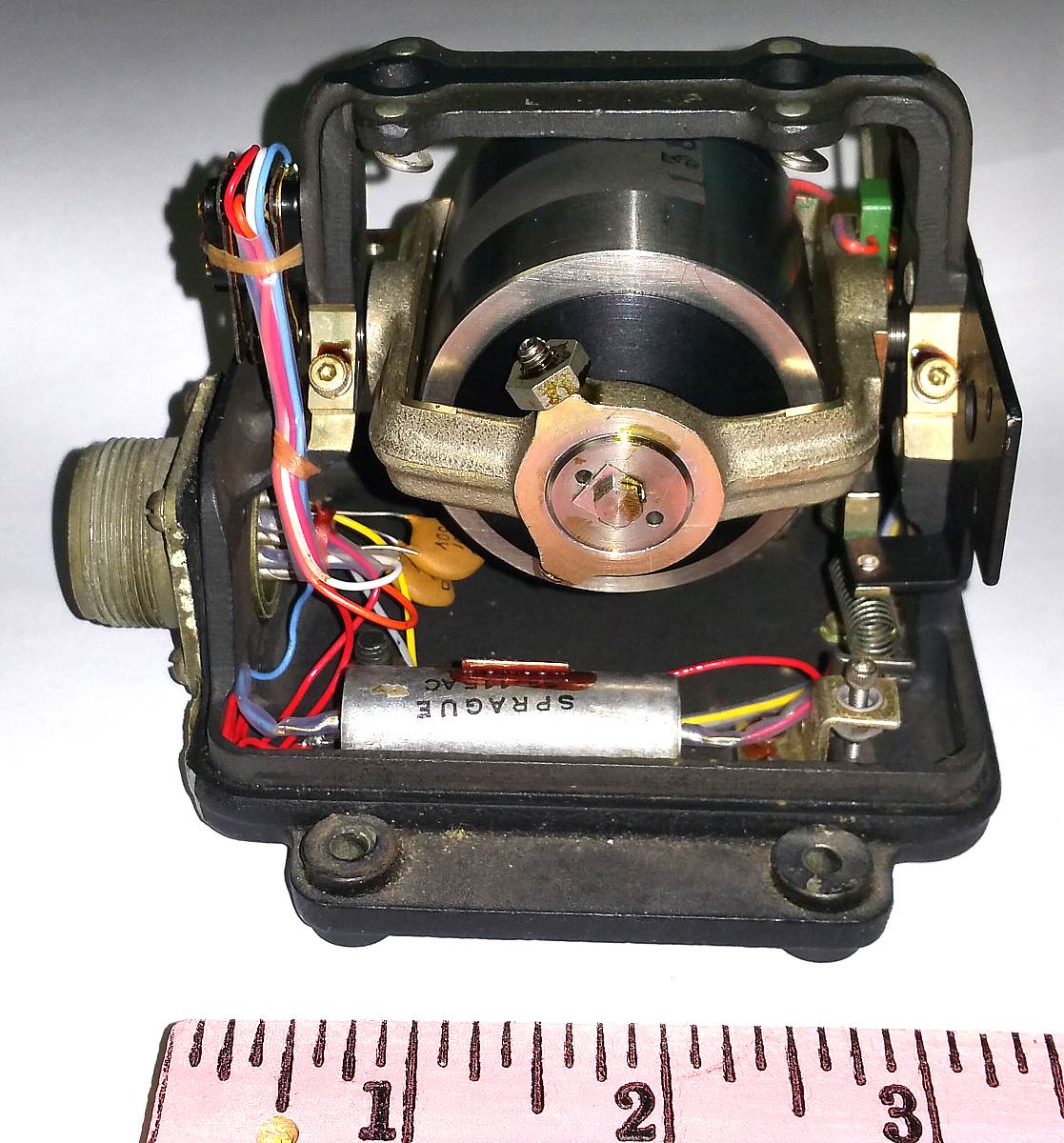
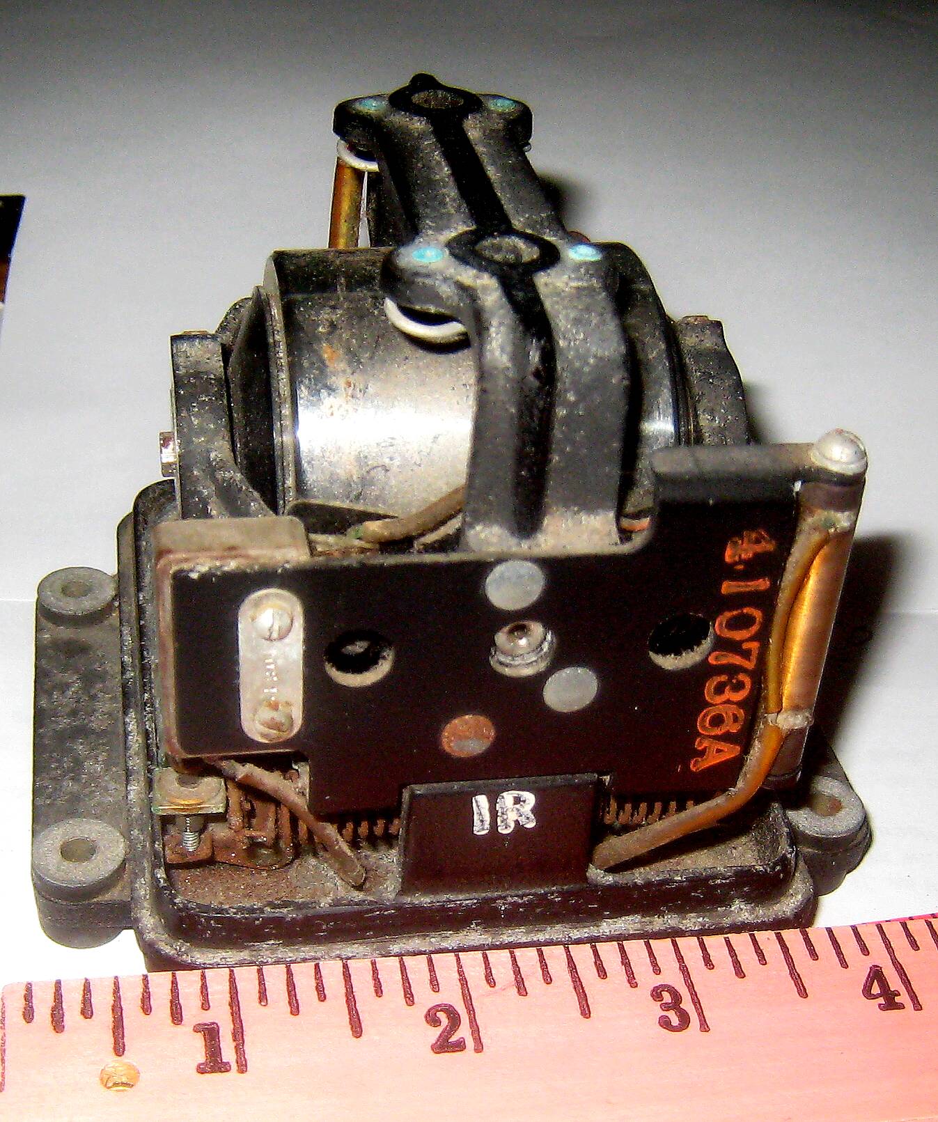
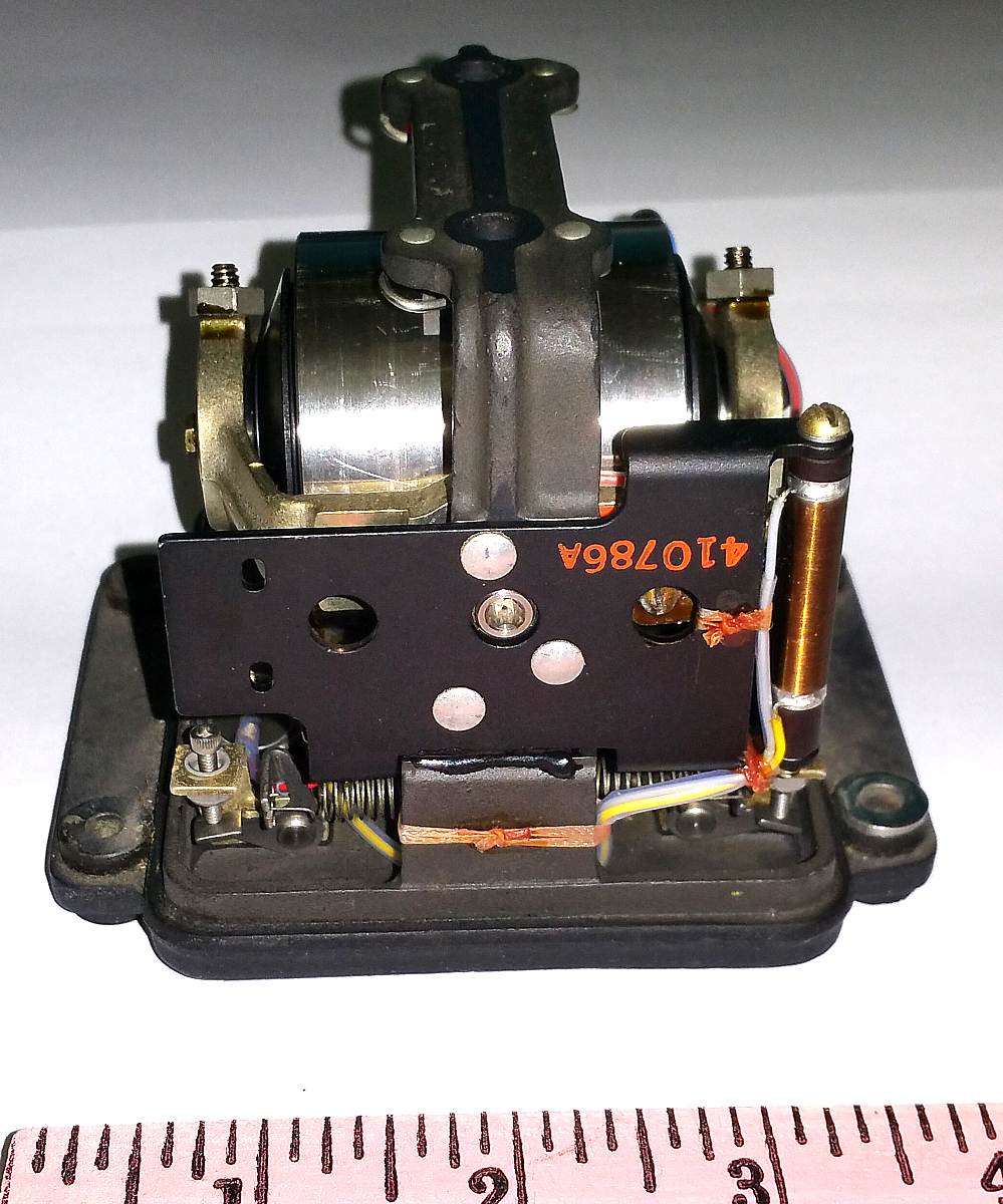
"my" defunct 1952 rate gyro & a working purchase
- started December 2018, updated February 26, 2019.
Norman Paik was an army friend and was later associated with Litton Gyroscope. He died in December 2018.
His widow, Kathleen, had heard Norman and I talking gyroscopes.
So, what do we have here??
|


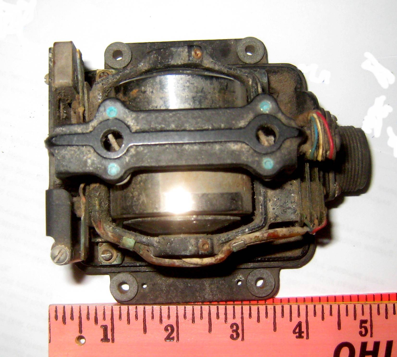
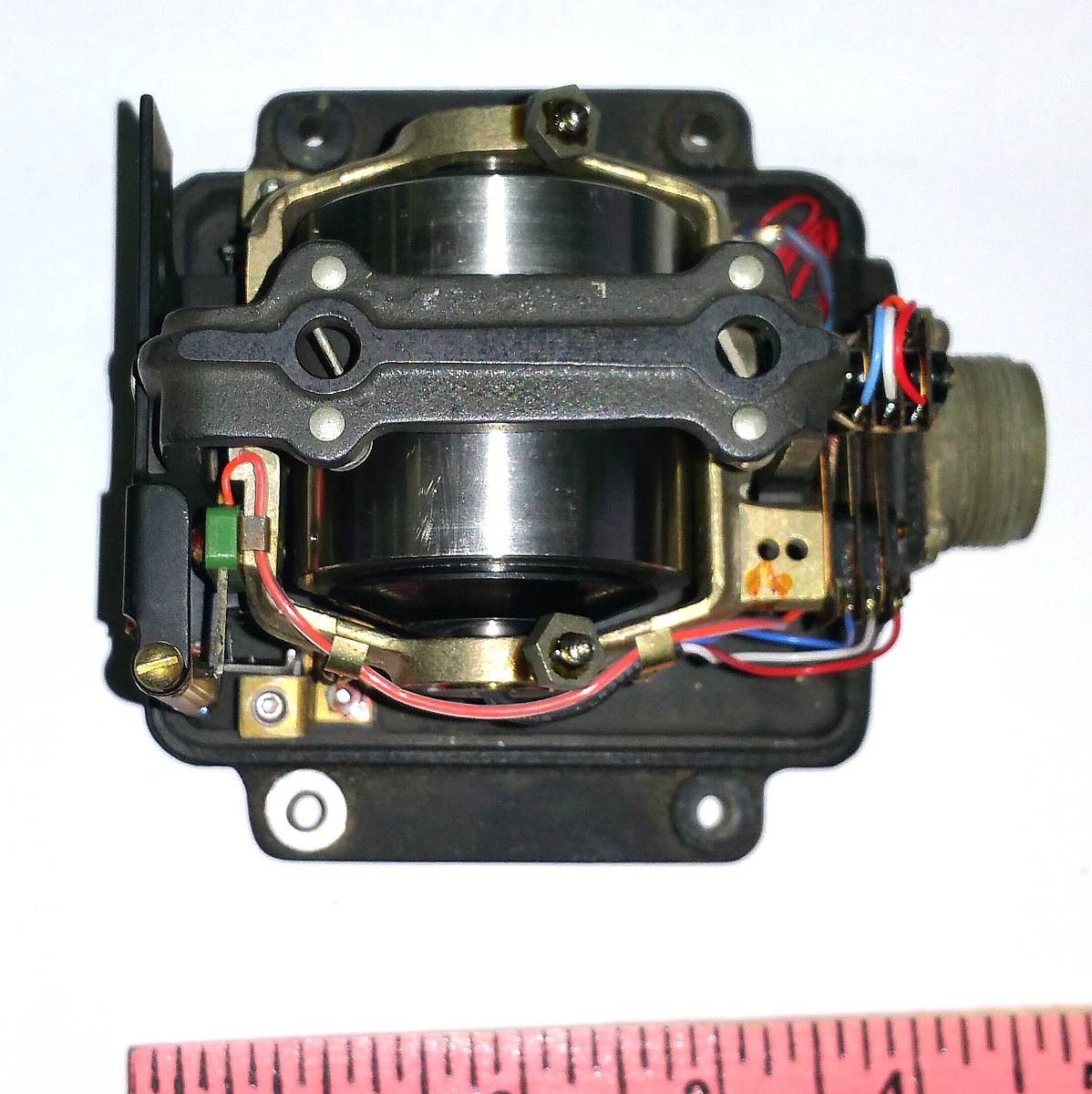
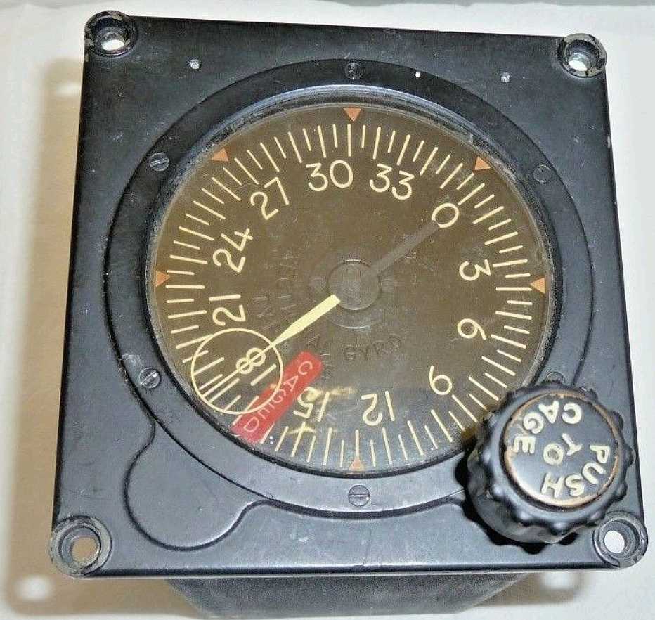
Vtg Aircraft Part SPERRY Directional GYRO Indicator TYPE C-5 Aviation gyroscope
| 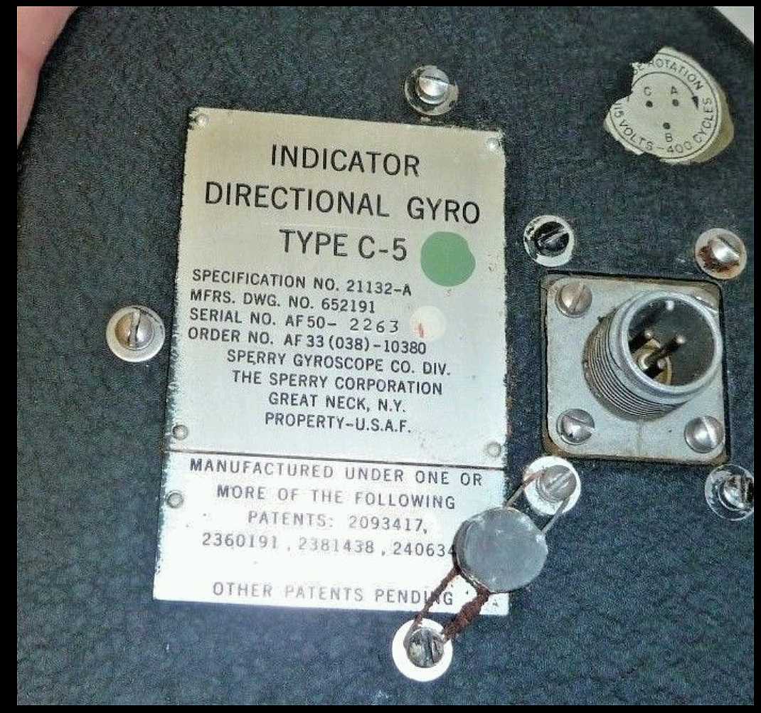
| AirForce type C-1, C-5, (Sperry)
Handbook, Operation, Service, Overhaul Thanks to Marc Verdiell
Marc purchased a nice, variable frequency, 3-phase 115 volt output power supply,
and spun this unit up July 16th, 2021 - Initial Report
|
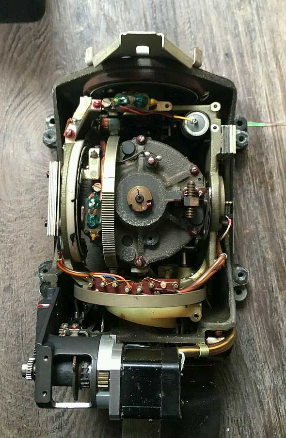
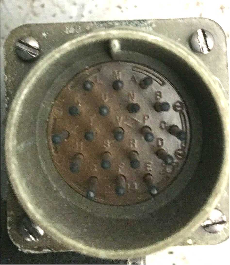
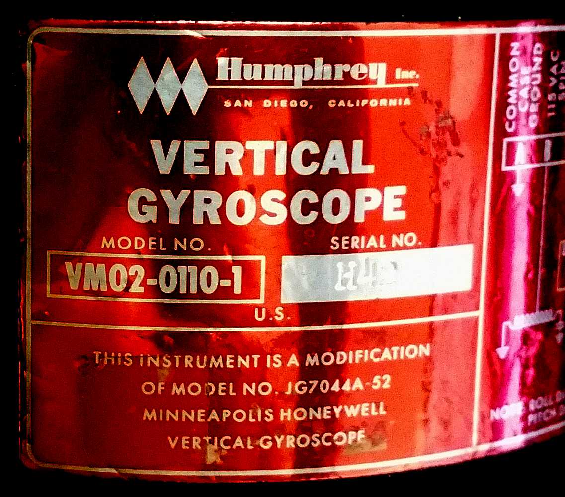
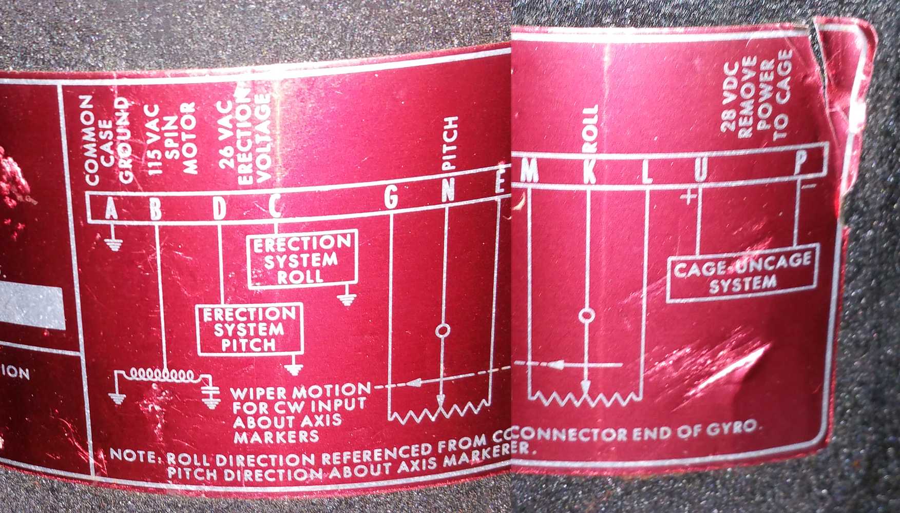
Humphreq Vertical Gyroscope Aircraft Helicoptor VM02-0110-1

|
|
|
|
|
Vertical Gyroscope thanks to Ken Shirriff
ad from e-bay |
| Elementary | Non-technical Introduction to Gyro Gompasses
| Good Start
| A 1944 Sperry (before Rand) GYRO-COMPASS GYRO-PILOT MANUAL
| Add gun stabilization
| A navy document MK-19 and MK-23 gyro compass. 6.5 MByte
| Wonderful ;-))
| THEORY OF THE GYROCOMPASS ( www.maritime.org/fleetsub/elect/chap17.htm ) 1,2 MByte
Local copy)
| Directional Gyro Indicators
| AirForce type C-1, C-5, (Sperry)
| Handbook, Operation, Service, Overhaul Apollo reference
|
"Apollo guidance, navigation and control - Design survey of the Apollo inertial subsystem"
| "Apollo Guidance, Navigation, and Control (GNC) - NTRS - NASA" THE collection of Apollo info including Spec for procurement of Apollo Inertial Reference Integrating Gyro Thanks Mike Stewart |
Temporary Other - Feb 2018
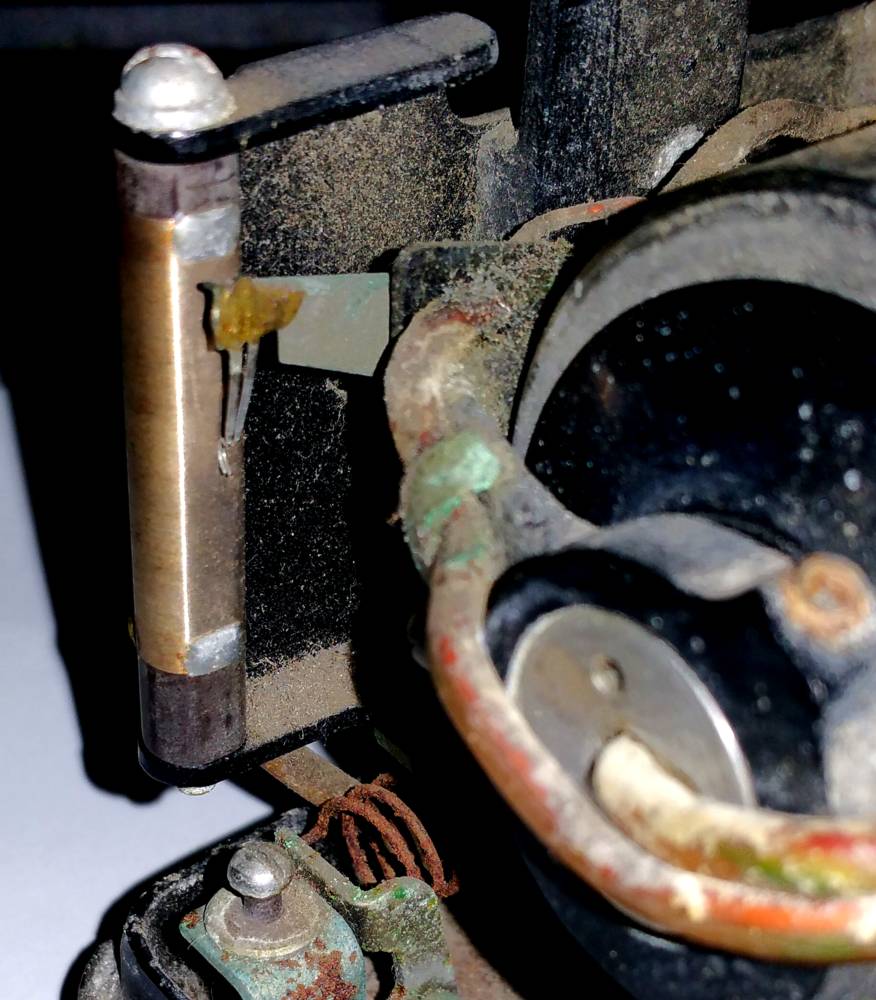
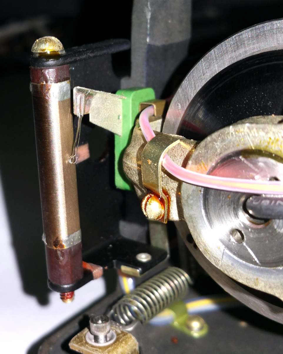
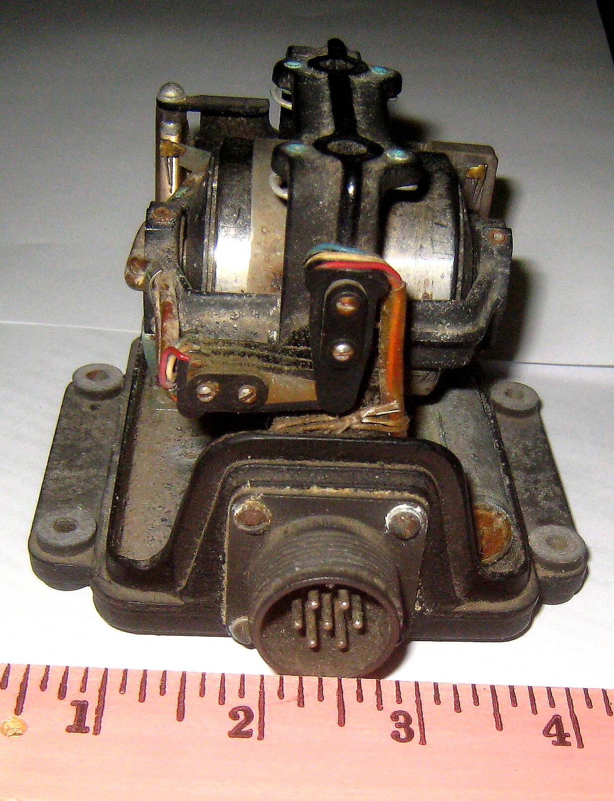
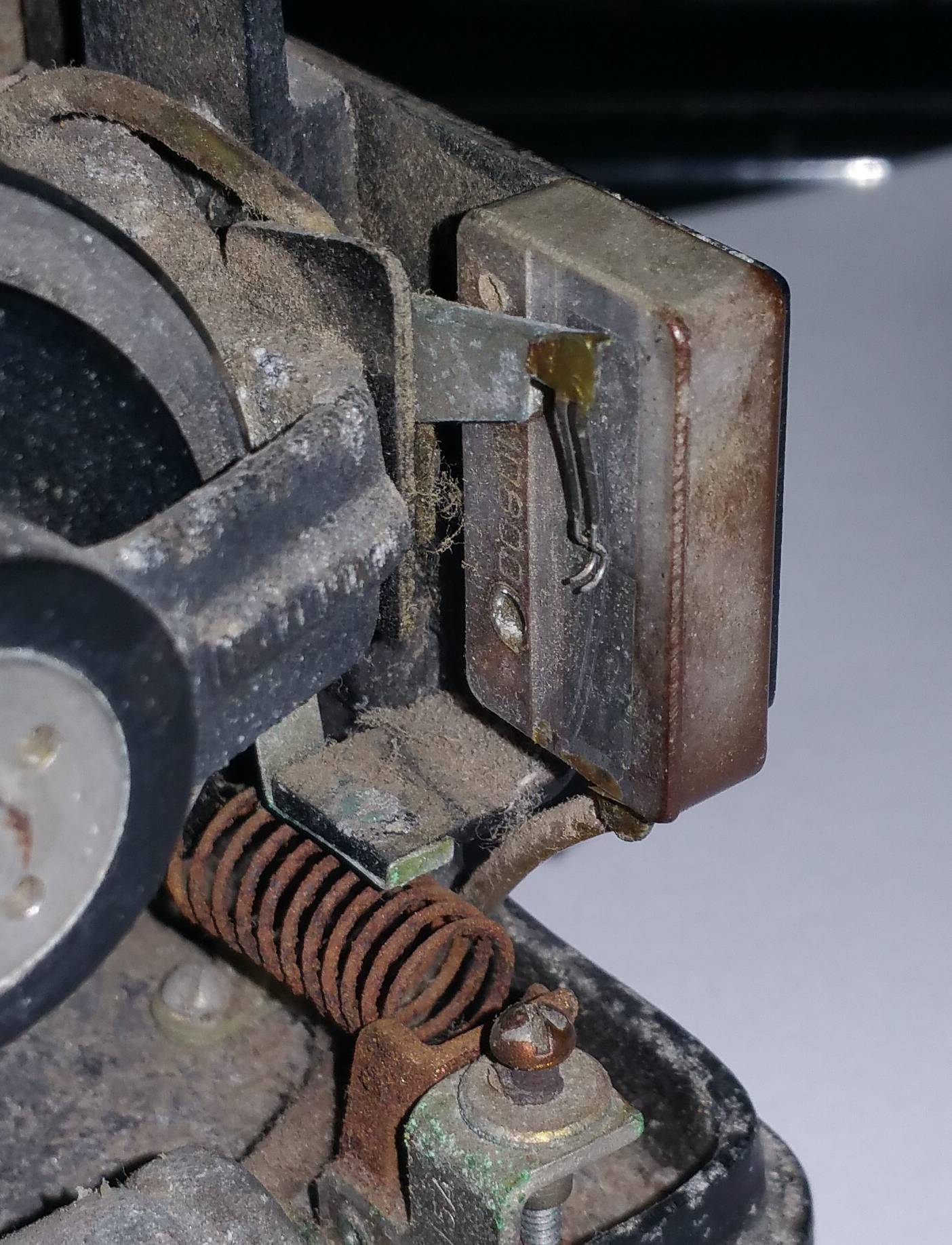
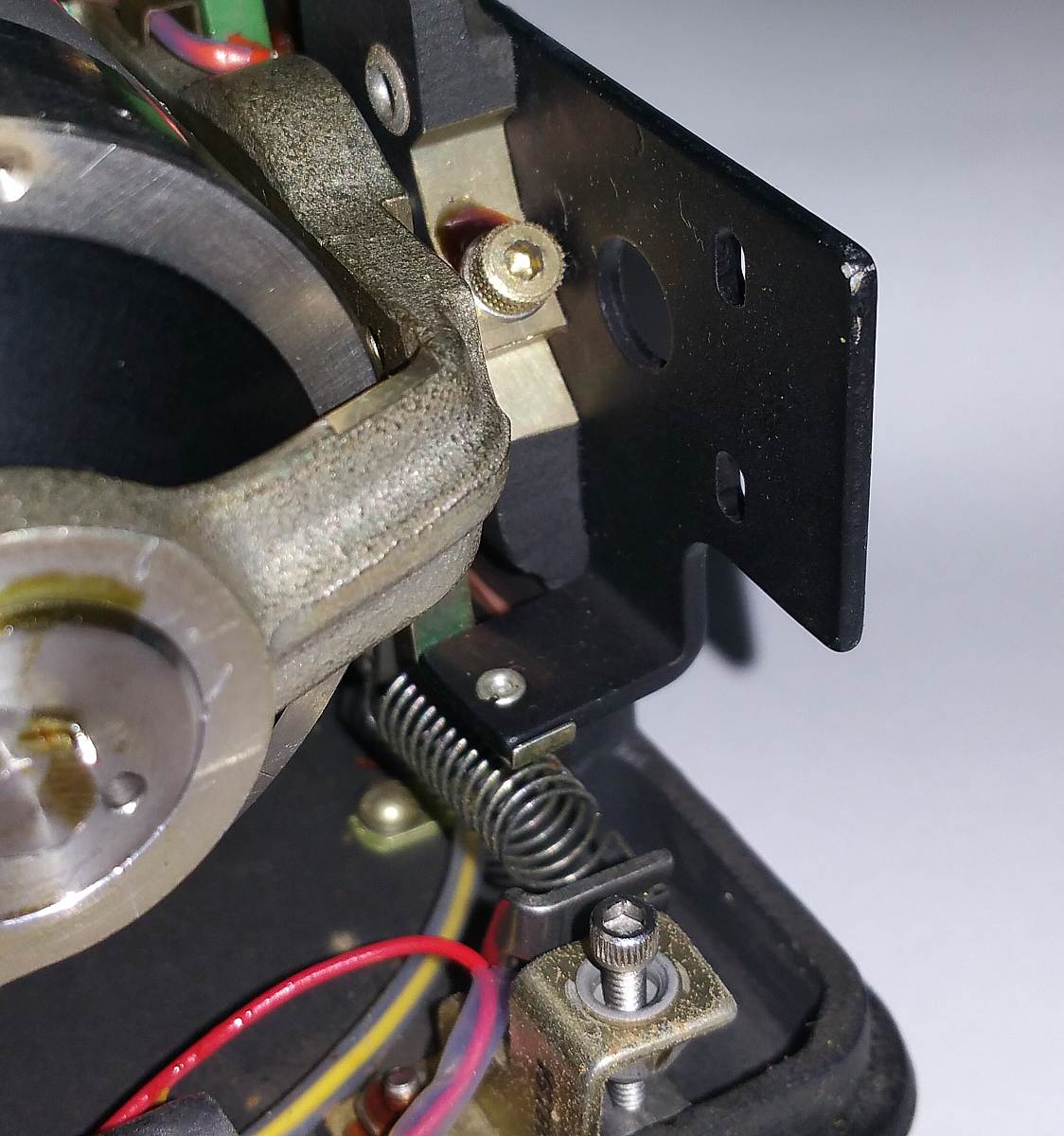
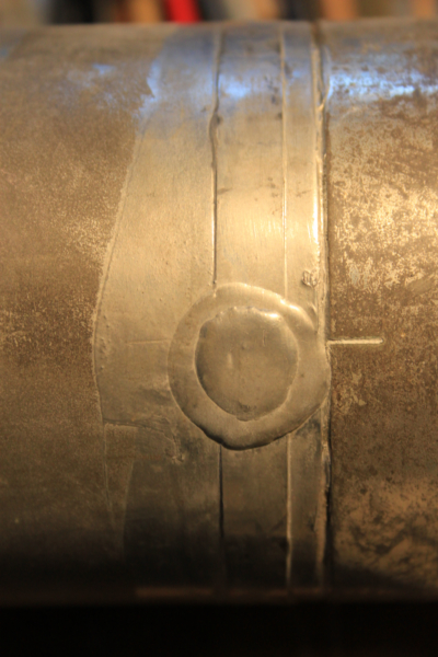
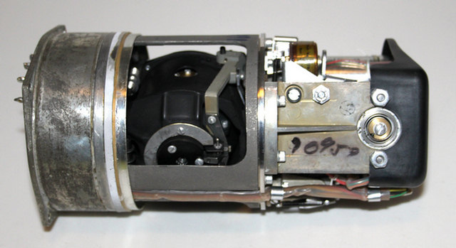
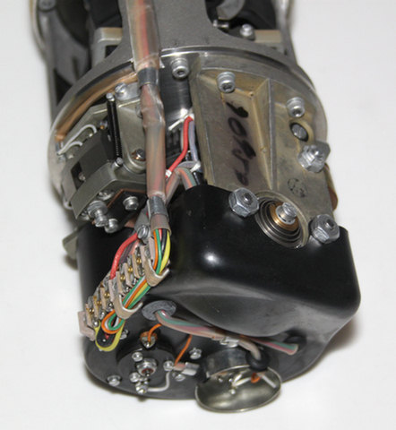
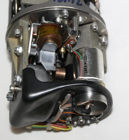
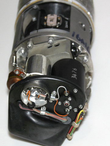
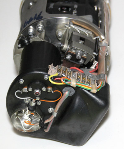
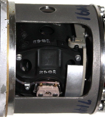
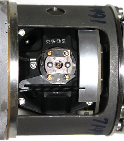
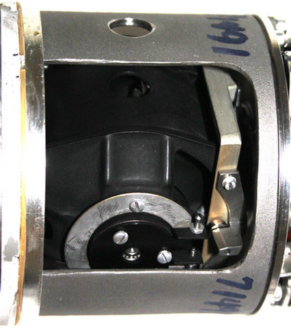
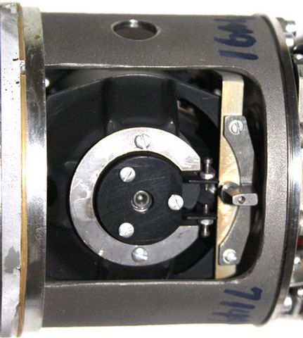
from "mmwave.zilg@t-online.de" please have a look to the photos. The "golden" gyro was fully tested in 1994. Both seem to be in good working condition. Both have 3,4 kg and give the same noise shaking slightly... Which one should i open ? I think the best way will be to desolder a small part of the thin sheet metal strip of 1 cm size around the gyro, beginning at the thick solder point and then continue mechanically with assisted heat and rolling the sheet metal over a kind of a can opener. Best regards Jochen
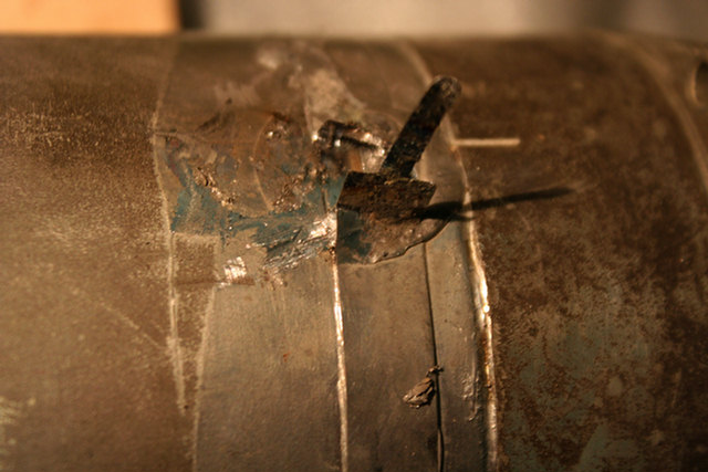
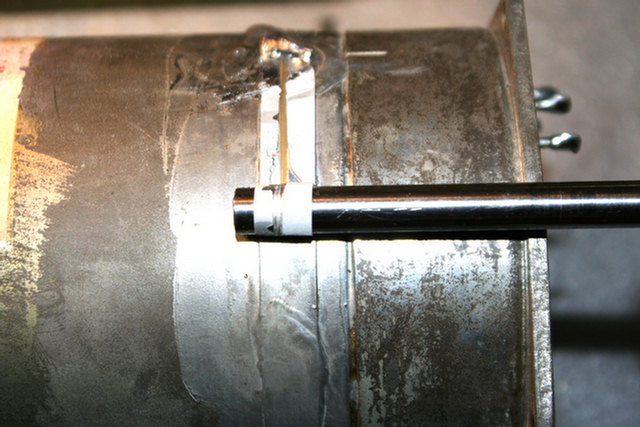
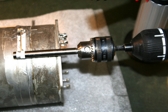
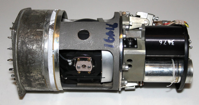
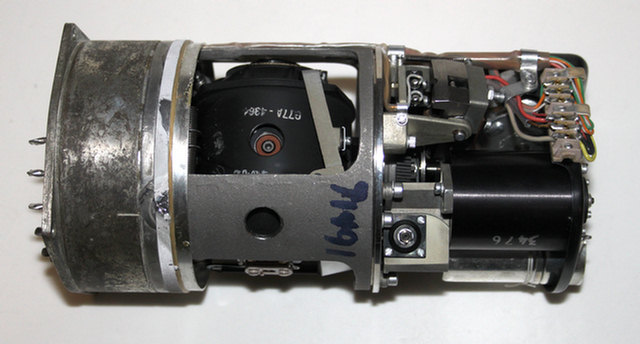
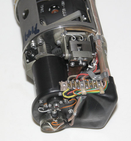
as announced i opened the gyro.
Please have a look...

Due to the size of the data i reduced the resolution of the pictures.
If you want more details then tell me what picture you mean...

Best regards
Jochen
|


|
Ignacio Menendez May 15, 2019, sent:
also see PIGA accelerometer | 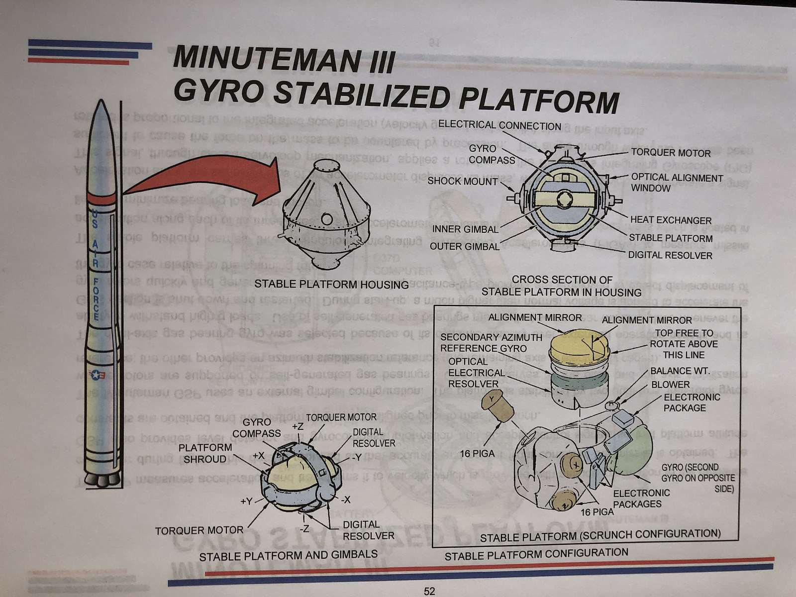
| 
| 
|
| Apollo AGC Part 9: Unboxing my Apollo IRIG Gyroscope, by CuriousMarc |
Gyros & Stuff from Brooke Clarke < brooke @ pacific . net > Tue, Jul 23, 2019
Hi Ed: While surfing things related to Apollo I came across a link to your gyro web page. Recently I saw the movie "First Step" where, after some research, discovered the "Box Sextant" used to train the astronauts to find the navigation stars they would need to sight for the AGC. https://prc68.com/I/Nav.shtml#Box_Sextant My Gyroscope web page is at: https://prc68.com/I/Gyroscopes.html also see: https://prc68.com/I/Gyroscopes.html#Norden - it never worked I also did a lot of research on W.W.II torpedoes and discovered a major disconnect between the max range and their ability to hit anything. The max range is over 10X the range at which they can hit a target. Ford Inst. Co. patented the torpedo data computer and also the Gun Director for big guns on ships. They both are trying to solve the same problem of a ballistic weapon firing from a moving platform trying to hit another moving platform where the time from firing to impact is quite long. It's my contention that torpedoes of that type, big guns that fire at high elevation angles and iron bombs delivered from a horizontal plane have never been accurate weapons. https://prc68.com/I/Torpedoes.html#Range__Accuracy https://prc68.com/I/Aircraft.shtml#Bombing And the information most related to your Nike stuff: https://prc68.com/I/Aircraft.shtml#Shooting_Down The Sidewinder missile and proximity fuse were motivated by how hard it was to shoot down aircraft, see: https://prc68.com/I/ChinaLakePatents.html -- Have Fun, Brooke Clarke https://www.PRC68.com http://www.end2partygovernment.com/2012Issues.html axioms: 1. The extent to which you can fix or improve something will be limited by how well you understand how it works. 2. Everybody, with no exceptions, holds false beliefs. |
Commercial Usage - Jan 7, 2020
taken from https://www.vectornav.com/support/library/imu-and-ins, Jan 7, 2020
|
Inertial Measurement Units and Inertial Navigation
The Inertial Measurement Unity (IMU) is an integrated sensor package that combines multiple accelerometers and gyros to produce a three-dimensional measurement of both specific force and angular rate, with respect to an inertial reference frame, as for example the Earth-Centered Inertial (ECI) reference frame. Specific force is a measure of acceleration relative to free-fall. Subtracting the gravitational acceleration results in a measurement of actual coordinate acceleration. Angular rate is a measure of rate of rotation. It is important to note that in recent years the term IMU has become an umbrella term used to describe a wide assortment of inertial systems including Attitude Heading Reference Systems and Inertial Navigation Systems. In the context of this writing, we will use the term IMU in accordance with its classical meaning to describe the combination of only a 3-axis accelerometer combined with a 3-axis gyro. An onboard processor, memory, and temperature sensor may be included to provide a digital interface, unit conversion and to apply a sensor calibration model. The IMU by itself does not provide any kind of navigation solution (position, velocity, attitude). It only actuates as a sensor, in opposition to the INS (Inertial Navigation System), which integrate the measurements of its internal IMU to provide a navigation solution. For instance, an Inertial Navigation System (INS) uses an IMU to form a self-contained navigation system which uses measurements provided by the IMU to track the position, velocity, and orientation of an object relative to a starting point, orientation, and velocity. The field of inertial navigation is a well-established field of study and extends way before the advent of MEMS technology. The first inertial sensors were developed and tested by rocket designers such as Robert Goddard and Wernher von Braun in the early 1930s. Later inertial sensors technology was perfected by institutions such as Drapers Labs, creating the first Inertial Navigation Systems. Inertial navigation made possible many of the great spaceflight achievements such as the Apollo program. Up until the advent of MEMS technology, inertial sensors consisted of precision mechanical gyros and accelerometers. Due to their high costs, inertial sensing technology was reserved for high-end aerospace applications. As MEMS inertial sensor technology has matured over the years low-cost solid state chip level inertial sensors have become available as alternatives to the older mechanical inertial sensors. While these new MEMS based sensors offered lower overall performance than their mechanical counterparts, they also offered drastically reduced size, power, and cost. The inertial sensor market spans an enormous range in terms product price and performance. There are six orders of magnitude difference in price and performance between the highest end inertial systems and the lowest. This can lead to great confusion for many buyers when dealing with component selection and pricing. The goal of this guide is to provide a crash course on what is available and possible with inertial sensors. First of all there is not agreed upon definitions of high, medium, and low-grade performance when it comes to inertial sensors. What one expert considers high end may be low end to another and vice-versa. When you are searching for inertial systems you may come across the terms Tactical grade or Automotive grade. These terms define different performance classes which similar inertial sensors can be grouped. In general, inertial sensors can be grouped into one of the following four performance categories.
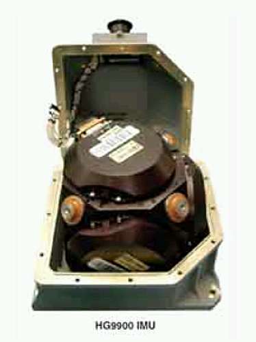
Aside from the custom inertial navigation systems used on Intercontinental ballistic missiles, the marine grade inertial systems is the highest grade sensors that are commercially available. They provide the best overall performance in terms of both determining position and orientation. These systems are typically used on ships, submarines, and some spacecraft. A high-end marine-grade INS can cost over 1 million dollars. These systems will typically provide un-aided navigation solution drifts that are less than 1.8 km per day. This means that if the device were left stationary for one day, due to slight errors in the sensors and imperfect sensor calibrations, after integrating the position solution, the calculated position after one day would be 1800 meters away from the sensors actual position. This represents the best that is possible with commercially available inertial sensing technology. Navigation grade systems have slightly lower performance than the marine systems and are typically used on commercial airliners and military aircraft worldwide. A navigation grade system will typically have less than 1.5km drift per hour. These systems cost around $100,000 and have a size of about 6in x 6in x 6in. A navigation grade system can be combined with GPS to create positioning systems that are accurate to within centimeters in real-time. An example of a navigation grade IMU is the HG9900 IMU made by Honeywell.
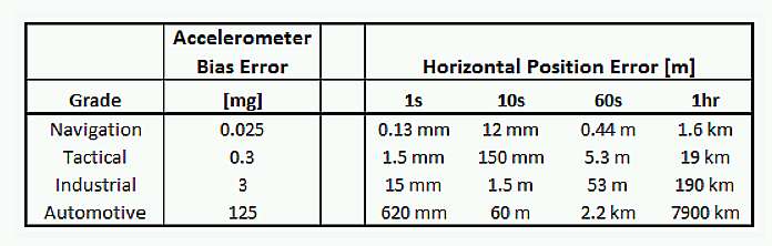
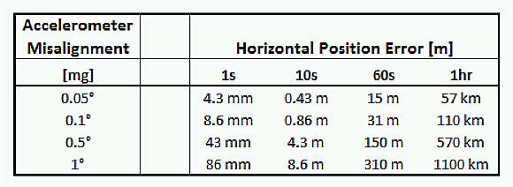
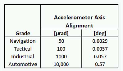
The lowest grade of inertial sensors is often referred to as automotive grade. They are typically sold as individual accelerometers or gyros, however many companies have begun to combine multiple accelerometers and gyros from different manufactures to create self-contained IMU units. This grade of IMU's are not accurate enough to be used for inertial navigation even when integrated with other navigation systems such as GPS. These sensors typically have good repeatability, and if they are calibrated after installation then they can be used as part of an industrial grade sensor, an Attitude Heading Reference System (AHRS), or a Pedestrian Dead-Reckoning System. Typically these sensors are used in anti-lock braking systems, airbags, active suspension systems, gaming controllers, and entertainment systems. The main difference between automotive grade and industrial grade lies in the quality of sensor calibration. Determining which type of inertial sensor is right for your application can be a difficult process due to the lack of information available pertaining to the subject. Datasheets for inertial sensors can be very confusing and make it difficult for potential buyers to compare different products. The first step is to determine which grade of sensors is required for your application. Trying to use an industrial grade IMU in an application that requires navigation grade performance will only lead to enormous levels of frustration and confusion. This is the step where you want to pick the right tool for the job. You don't want to use a bulldozer where you need a shovel, and you certainly don't want to use a shovel where you should be using a bulldozer. In order to compare the performance of the different grade inertial sensors we will analyze them for two different use cases. Each case corresponds to a common use for inertial sensors. This case corresponds with using an IMU as a stand-alone inertial navigation solution without the assistance of GPS or any other external reference. Below is an overview of the typical errors for each grade of inertial sensors. When determining how well an inertial system will perform as an inertial navigation system, a first order estimate is to assume that the errors in position will be caused only by the errors in the accelerometer bias. Errors in the position estimate will actually be caused by many factors including the gyro bias stability, accelerometer scale factor uncertainty, and many other parameters, however the largest contribution will be due to un-corrected errors in the accelerometer bias. Any bias in the accelerometer horizontal axes will cause an bias in the calculated orientation of the object in terms of pitch and roll. Since we have to subtract out gravity from the IMU accelerometer measurement prior to integration, any error in the calculated orientation will cause us to not correctly subtract out the gravity from the acceleration measurement. Since the amount of acceleration of an object is typically much smaller than the acceleration due to gravity (9.81 m/s^2), subtracting out gravity incorrectly can lead to very large errors in the estimated inertial acceleration which will directly integrate into position errors. The error in position due to a bias in the accelerometer will have quadratic growth with time. The misalignment of the accelerometer axes will also performance of the inertial navigation system. It is important that each of the axes of the accelerometer are aligned perfectly with an orthogonal coordinate system. Errors in misalignment will propagate into position errors as shown in the table below.
The above table reinforces the importance of sensor calibration. Automotive sensors typically have package misalignments of around 1 and inter-axis misalignments of greater than 0.1. Industrial grade inertial sensors will typically have misalignments calibrated to within 0.05. The gyro noise and bias uncertainty will affect the position estimate error of an inertial navigation system. The affect of the white noise upon the integrated orientation angle is quantified by the gyro angle random walk parameter. The parameter multiplied by the square root of the integration time gives an estimate of the 1 sigma angle walk due to the gyro white noise. For navigation grade systems this can be a predominant source of error. For tactical, industrial, and automotive grades this does have an effect, however it can have an order of magnitude less effect than an accelerometer bias error that is left unaccounted for.
You can estimate the amount of horizontal position error for a static case by simply using the accelerometer bias error given in the manufactures datasheet. For example let us look at a typical automotive grade MEMS accelerometer datasheet. The below excerpt is from the datasheet of the LIS344ALH 3-axis MEMS accelerometer made by ST Micro.
From the datasheet we find that the zero-g level is known to within 5%. Since Vdd for this part is 3V, this means we have a 75mV uncertainty. The datasheet also tells us that the sensitivity is 0.6 mV/mg. This means that the total uncertainty in the accelerometer bias is 125 mg. To calculate the maximum static case horizontal position error use the following formula:
In the above equation replace T with the time measured in seconds. For instance after 10 seconds with this accelerometer you could have as much as 60 meters error in calculated position. The uncertainty in the accelerometer bias is the primary reason why automotive grade accelerometers cannot be used for inertial navigation. If this sensor is properly calibrated however, then the uncertainty in the accelerometer bias can be reduced by nearly two orders of magnitude, reducing the horizontal position error to within a few meters over the same 10 second period. Errors due to axis misalignment can be calculated using the below formula.
The uncertainty due to the gyro angle random walk can be calculated as
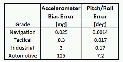
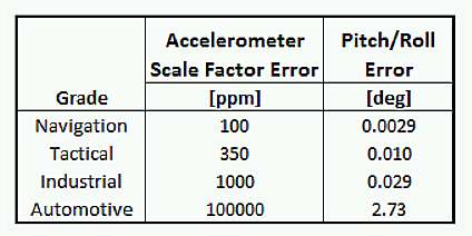
Inertial sensor can also be used to determine the orientation as a function of time. Without an absolute reference an IMU can only be used to track changes in orientation from some initial point in time. For absolute orientation tracking you will need to combine an IMU with an absolute reference sensor such as magnetometer, camera, or GPS. Combining an IMU with a magnetic sensor creates what is known as an Absolute Heading Reference System (AHRS). For this case we will look at the error caused by the accelerometer that influence the orientation estimate. An AHRS determines orientation by making the assumption that the measured acceleration vector minus the known inertial acceleration is equal to the gravity vector. For cases where the actual inertial acceleration is unknown the AHRS assumes that the measured acceleration on the accelerometer is the actual gravity vector. Due to this assumption any errors in the accelerometer will translate into errors in the estimated direction of the downward direction. The gyros will dampen out much of the time based disturbances in the acceleration, however any constant errors in the accelerometer calibration parameters will directly propagate into orientation errors. A bias in accelerometer will affect the pitch/roll by perturbing the measured acceleration vector. This will affect the direction of the measured gravity vector, directly contributing to errors in the estimated pitch and roll. The below table shows typical errors in pitch and roll that are contributed due to the errors in accelerometer bias.
Errors in accelerometer bias for automotive grade sensors are mainly due to imprecise calibration. The errors in the industrial and tactical grade are typically due to changes in temperature which cause the accelerometer bias to deviate in ways that cannot be accounted for by the sensor calibration model. The accelerometer bias may also be subject to long-term drift that isn't accounted for in the sensor model. Errors due to accelerometer misalignment will on a first order translate directly into errors in pitch/roll. Shown below are typical misalignment calibration accuracy for each grade inertial sensors.
Misalignments are removed by performing a tumble test during the calibration procedure. The errors due to scale factor of the accelerometer can also contribute to the errors in the measured orientation. The magnitude of error is dependent upon the residuals after calibration. Shown below is the typical accelerometer scale factor errors for each of the different grad IMU's.
The maximum error in pitch/roll can be analyzed by assuming that the sensor is in an orientation where the pitch and roll both equal 45. In this case a scale factor error in either axis will stretch one dimension of the vector, thus affecting the measured angle. The gyro scale factor has a substantial error on the accuracy of the integration of the angular rates during dynamic motion. If the scale factor is off, then the motion tracked by the gyros will not be correctly scaled and significant errors may result after the motion is complete. As an example consider the case of picking up an IMU, rotating it around the one of its axes by 360 degrees and setting it back down. Ideally the unit should read the same orientation as it did prior to the maneuver. The table below shows some the errors for this simple maneuver for each grade sensor.
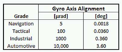
The table shows an order of magnitude difference from the navigation grade to the tactical grade, an order of magnitude from the tactical to the industrial, and two orders of magnitude from the industrial to the automotive. As you can see from the table, automotive grade sensors do not provide sufficient accuracy for neither inertial navigation nor accurate orientation tracking. Only when the automotive sensors are subjected to a thorough calibration do they provide sufficient performance to perform basic navigation techniques. The gyro misalignment will affect how the angular rates are measured in each of the coordinate directions. Misalignment causes distortions in the measured angular rate vector, which result in errors in resulting orientation after the angular rates are integrated. As a simple example consider the same case described above for the gyro scale factor where we rotate the IMU around a only the Z-axis by 360 degrees and return to the same orientation. If there exists misalignments in the other X and Y axes then they will inadvertently pick up angular rate from the Z-axis rotation even though no physical rotation was conducted around the X and Y axes. The table below outlines the maximum amount of error that would be recorded in pitch and roll assuming that the given amount of axis misalignment was present.
As with many of the other parameters you can see that there is clearly an order of magnitude difference in performance between each of the different grades with respect to errors due to gyro axis alignment. |


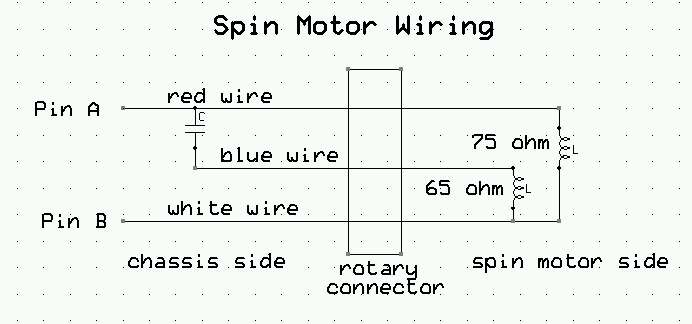
Initial Sperry C-5 Spinup Report - from Marc, July 16, 2021
|
Ed,
I got the gyro to do self-leveling! Cleaned the contacts, and I could see it switching the voltage to the coil. But it’s quite subtle – it moves very slowly. It sends a pretty low voltage to the rotor coil – a few volts only, from an auto-transformer. It’s on purpose. It engineered to compensate drift, so it’s about the same order of magnitude as the drift induced torque, just a bit more. Takes several minutes for it to get back to center if you purposely (manually by pushing on it) torque it off center. It’s still a pretty noisy beast, and it sometimes makes scary tones. I would think its bearings are pretty much done, we should probably not spin it too much more. But I learned a lot and did not break anything. I was very impressed on how incredibly stiff against any rotation it is once it is spun up. When you try to push it around, it feels like it is bolted down solid. By pushing really hard you can torque it up or down by precession, but the base rotation is so small you will not feel it nor will you see it change its indicated angle. It’s as if it was locked in place solid. Now I understand why they spin bullets and rockets so they go straight, but I did not expect the effect to be so incredibly strong. Marc |