Williams Tube
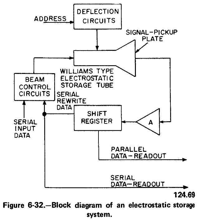
A representative tube that is employed for this purpose is the Williams tube. The Williams tube is used in a system arrangement similar to the one shown in figure 6-32.
CONSTRUCTION.-The overall construction
and deflection system of the Williams tube is
very similar to that of the familiar television
picture tube. However, the tube possesses two
additional features. The first is that poor
system.
conductor material, instead of the usual fluorescent
material, is used to coat the inside of the
face of the tube. The second feature is that a
metal "signal-pickup" plate is placed in contact
with the outside of the glass face of the tube.
Consequently, a CAPACITOR is formed, con-
sisting of the inside coating, the glass face, and
the signal-pickup plate.
This capacitor is charged and discharged by the electron beam within the tube. Let us first consider how the charging operation is accom- plished. If the electron beam is greatly accelerated by a high potential at the accelerating anode of the tube, electrons in the interior coating are "knocked" loose by the impact of the beam electrons. This phenomenon is known as secondary emission. The interior coating acquires a positive charge as the liberated electrons are drawn away to a nearby, positively charged anode. Since this coating consists of a poor conductor material, the positive charge remains within the very small area of beam impact.
WRITING.-By gating the electron -beam on and off (by means of the control grid) as it is swept across the face of the tube, it is possible to store charges that represent the value of the voltage at different instants of time. This procedure produces "writing." If the gating voltage that is applied to the control grid is a serially applied binary word, the word will be stored in the form of charged areas across the face of the tube. These areas represent charges on many individual tiny capacitors that share one common electrode which is the signal-pick-up plate.
READING.-Reading (capacitor discharging) is accomplished by using an electron beam sweep voltage which is not gated on and off (as was true in the writing process). The discharge path of each one of the individual capacitors (charged areas) is through the electron beam.
Note that there is a relationship between time, which is provided by the beam sweep, and the physical location of the individual capacitors.
As the beam sweeps across the tube face, the flow of each pulse of discharge current through the signal-pickup plate indicates the presence of a stored charge within a given area.
The series of pulses thus produced is usually applied to a shift register. The shift register shifts at a repetition rate that is controlled by the tube sweep voltage. Consequently, if NO PULSE appears at the instant corresponding to a bit-position in the original stored binary word, a binary zero is shifted into the register. After all of the pulses have been collected, the original binary word (as it had been stored in the tube) is now present in the shift register, and is ready for any subsequent parallel or serial readout and use. Readout from the register involves a nondestructive sampling of the voltage levels contained in the register. Thus, readout of a given bit of data can be repeated as many times as necessary.
Readout of data from the Williams tube is destructive, and the stored charge is "destroyed" during the readout process. This data can be restored by writing it back into the tube. This is accomplished by feeding the contents of the shift register through the beam-control circuits to the control grid of the Williams tube in order to repeat the writing operation.
Computer words are written across the screen at a density up to 1000 bits per inch. Selection of a given location on the face of the tube for either reading or writing requires accurate deflection of the electron beam. The location of each word is therefore identified by an "address" in terms of its X and Y coordinates. This information, which is digital, is converted into an analog voltage to permit the beam to be directed to any spot on the screen.
COMPARISON OF ELECTROSTATIC AND MAGNETIC CORE STORAGE SYSTEMS
When comparing electrostatic and magnetic storage systems, the time required to select a given address (access time) is slightly greater using the electrostatic storage method than for magnetic core memories due to the increase in time necessary to produce a voltage of the accuracy required to locate the desired data. Further, once data is stored in cores, it is seldom (if ever) necessary under normal operating conditions to re-record the data lost as a result of leakage. The retentivity of the core stores the data indefinitely. Using the Williams tube (elec- trostatic storage), data stored must be periodi- cally re-recorded to compensate for leakages in the glass dielectric between the insulation material coated on the tube face and the metal pickup plate outside of the tube.