This description of magnetic core memory is from
	      DIGITAL COMPUTER BASICS
	Naval Education and Training Command
               Rate Training Manual
                NAVEDTRA 10088-B

Revised 1978

United States Government Printing Office
Washington, D.C.
From a copy owned by Computer History Museum, starting at page 95.
MAGNETIC CORES
A representative magnetic core is shown in figure 6-1. It is constructed of a ferrite (highly permeable) material. In computer memory applications the ferrite core is magnetized by a flux field produced when a current flows in a wire (drive line) that is threaded through the core (explained later). It retains a large amount of this induced flux when the current is removed. Flux lines can be established clockwise or counterclockwise around the core, depending upon the direction of the magnetizing current. A current in one direction establishes a magnetization in the core in a given direction. Reversing the direction of the current flow reverses the direction of the flux field and the core magnetization. These two unique states represent "0" or "1" respectively.
In this discussion it is assumed that the time required to switch a core from one state to another is approximately 1.2 us. The drive pulse is presumed to be 2 us in duration with a total of 0.8 us rise and fall and 400 milliamperes maximum current.
MAGNETIZATION PROCESS
The state of magnetism of a core is explained using the hysteresis loop shown in figure 6-2, The points defined on the loop illustrate the magnetic flux density in gausses (B) as a function of the field (induced by the current) in oersteds (H).
In this diagram it is assumed that all magnetism has been removed from the core. (This condition is assumed merely to show how a magnetizing force is established in the core and how the core magnetism enters into its hysteresis loop. Actually, this core and all magnetic materials exist in nature in some state of magnetization as a result of the influence of the earth's magnetic field.) The 0 point in figure 6-2 represents a condition of 0 ampere-turns in oersteds (H) and 0 core magnetization in gausses (B). If a current pulse is conducted through the drive line (fig. 6-1) with an intensity which produces a magnetomotive force (MMF) of a magnitude +Hm (fig. 6-2), the core magnetization will change (saturate) as shown along the magnetization curve defined by the numbers 0, 1, and 2. This action establishes a flux density in gausses (B) in the core of a magnitude indicated here as +Bs.
If the current is returned to 0, the core magnetism does not return to 0 but drops along the loop to a point +Br (3). This amount of magnetism (which is referred to as residual magnetism) is only slightly less than that produced when the driving current was present. Thus, the core stores almost the entire amount of the induced magnetism.
Another pulse of magnitude +Hm would merely shift the core to +Bs again (from 3 to 2), and, after the pulse is removed, the core magnetism would return to +Br (2 to 3).
Now, if a current pulse of the same magnitude but in the opposite direction is conducted. through the drive line so that a MMF of an intensity -Hm is produced, the core flux shifts along the curve outlined by the numbers 3, 4, and 5 (-Bs). At 5 the core is again saturated but because of the current reversal, the magnetism is in a direction opposite to that first considered. Thus, the core saturates in the opposite direction when -Hm is applied.
When the -Hm magnetizing force is removed, the core magnetism drops along the loop from 5 to 6 (to -Br), and will remain magnetized (stores its magnetism) at the -Br level with negligible losses for long periods of time.
That magnetic cores are readily adaptable to computer storage application should be obvious. If the +Br state of the core is arbitrarily called the "1" state, then the -Br state will represent "0" state. In computer memory applications, several (up to 60 or more) of these cores are arranged to form computer words. The word content is represented by the magnetized state of each core to store either the "0" or "1" state, i.e., the magnetic state of the combined cores represents a computer word.
CORE WINDINGS
In order to be able to apply more than one drive current and to sense or inhibit changes in the core condition, it is necessary to use several core windings (drive lines). These windings are illustrated in figure 6-3.
Any change in the flux of a core induces a voltage in all wires passing through the core. Any induced voltage applied to the sense line (winding) is sampled to see how it affects the core. If the voltage sensed is large (over 50 millivolts), the core will change states. If a -Hm /2 is applied to the core, which is in the "1" state (+Br in figure 6-2), it will switch to a "0" state (-BS in figure 6-2). If the core is in the "0" state (-Br in figure 6-2) and a large +Hm/2 is applied to the core, it will switch to the "1" state (+Bs in figure 6-2). Because the contents of the core are determined in this manner, the current pulse corresponding of mmf -Hm is called a "Read Pulse." As defined earlier, because the core condition stored before sensing is destroyed during read-out, a memory utilizing this type of magnetic core storage element is referred to as a destructive-readout memory. If the data which was stored is to be used again, a restore (or rewrite) function is initiated to return the core to its original state.
MAGNETIZING CORES BY VECTOR SUMS OF CURRENTS
The use of windings to magnetize the core and to sense the signal resulting from the application of a read pulse is one method by which data can be readout or written into the internal storage facilities of a computer. The use of straight current-carrying wires is an alternate method used when space is critical and small cores are used, because it is very difficult to wind coils on a very small toroidal form. It is desirable to use small cores in order to increase the storage capacity per given area and decrease the core switching time.
The magnetic intensity and the flux around a current-carrying wire form patterns of concentric circles around the conductor. Because the core and the wire are concentric, some of the flux created by the wire passes through the core, as shown in figure 6-4.
If two current-carrying wires passing through a selected core are placed at right angles to each other, the effect is as though there was a single wire carrying the vector sum of the current. (See figure 6-5.)
Switching the core involves the use of vector addition. The vector sum, or resultant, of the magnetic intensities of two current-carrying wires placed at right angles to each other is a third magnetic intensity located midway between the two original magnetic intensities. If each wire carries 0.707 of the current required to switch a core and if a core is oriented in the direction of the resultant magnetic intensity, the core will switch. If only one wire carries current, the core will not switch. This method is called the "coincident current" method of core switching.
COINCIDENT CURRENT IN CORE PLANE ARRAY
Coincident current core switching is used with. an arrangement of wires and cores called a cord plane array, similar to that shown in figure 6-6. This 4x4 array is made by crossing long lengths of insulated wires so that they form a squared-grid arrangement. A 4x4 array has 16 cores arranged in a square pattern of four cores on each side of the array.
Cores are placed at the junctions of the grid wires in such a manner that they encircle the resultant magnetic-intensity vector. These junctions can be thought of in terms of Cartesian coordinates; the horizontal locations assigned an "X" designator and the vertical a "Y" designator.
If a current equal to one-half of the current value required to switch a core (half-write current) is applied through both X3 and Y2 in the direction to produce a "1" condition, the only core that will be switched is the core located at the junction of the X3 and Y2 wires. The other cores along wires X3 and Y2 will not be switched, because the intensity of the magnetic flux produced by only one-half current is insufficient. These cores are said to be "half-selected." Core X3-Y2 is switched (if it is not already in the 1 state) because of the resultant magnetic intensity created by the combined one-half current in a binary-"1" direction at the X3-Y2 junction. Any of the 16 cores in this core plane may be switched to store a "1" in a similar manner by the application of half-write currents through the associated X and Y wires.
The core at the junction of any two driving wires (one X and one Y) can be set to a "1" or "0" condition, depending on the direction of current flow through the driving wires.
To read the data (" 1 " or "0") which has been stored in a core requires the use of sense winding. This winding passes through the center of each core, as shown in figure 6-7.
Only one core in an array may be switched at a time. Therefore, when a read-current pulse is applied to wires X3 and Y2 (that is, opposite to the write currents), the magnetic flux of core X3-Y2 changes direction (if the core is storing a "1 "), thereby inducing a voltage in the sense winding. Any core may be read in a similar manner by application of a read pulse to the associated X and Y winding of the core.
If a core has not been switched by half-write currents, as explained, it contains a "0." On application of the read pulse to the X and Y winding of that core, the direction of the magnetic intensity in the core does not switch. Therefore, a pulse is not induced in the sense winding.
Consider now that all of the cores on line Y2 (figure 6-7) are storing a "1" and that the core at the junction of Y2 and X3 is being read. When read-currents (half-currents) are applied on lines X3 and Y2, all of the cores on line Y2 are disturbed. This disturbance causes low-amplitude (noise) inputs to be induced in the sense line along with the full-amplitude sense line input from the core at the X3-Y2 junction.
Two procedures are used to eliminate the effects of noise from adjacent cores during readout. These involve the use of disturb and strobe pulses. The disturb pulse (equivalent to a half read) is a drive signal of an amplitude (coercive force) -Hm/2 which is applied to a core immediately after a "1 " state is written in the core The disturb pulse (figure 6-2) drives the core magnetism from +Br (the state at which the magnetism is established in the core at the time the "1" is stored) to a point A on the hysteresis loop. When the -Hm/2 pulse is removed, the core magnetism returns to point B. A subsequent half-read pulse drives the core to point C, and when removed permits the magnetism to be established at D. (Let this be equivalent to the induced noise from a halfselected core where a selected core is being read.) Note that the change in core magnetism from point B to point D is less than the amount of change when the first half-read pulse is applied. Consequently, less noise will be induced in the sense winding from adjacent cores in figure 6-7 if a disturb pulse is applied on the line prior to reading the core at the Y2-X3 junction.
Noise pickup during reading is further minimized by strobing. This technique involves the selection of the mid-amplitude portion of the amplified sense pulse. Selection is accomplished by ANDing the amplified sense pulse with an accurately timed pulse referred to as the "strobe pulse." (See figure 6-8.)
Because the magnetic intensity around a core storing a "1" is switched to a "0" direction on receipt of a read pulse, the datum stored in that core is destroyed (destructive readout).
The ideal readout method is, of course, one in which the data stored are not erased, but remain stored for subsequent readout (nondestructive readout). With magnetic cores, however, if it is desired that a core which has been read should retain the stored data (a "1"), a subsequent write pulse must be applied to the core each time this "1" is sensed.
It may be desired to write each bit of a word into the internal storage of the computer, one bit per core array Usually the number of core arrays used for this purpose is the same as the number of bits per word. The arrays are stacked on top of each other with the first bit stored in the top array, the second bit in the next to the top array, and so on.
To permit storing the bits of a word in the same relative core position of the stacked arrays, the same X and Y driver wires of each array are connected in series or parallel. Thus, when the coordinate wires of one core in an array are energized, every corresponding core in the other arrays also is energized.
This method of driving each X and Y winding of an array in series or parallel with every corresponding X and Y winding on the other arrays of the assembly introduces a problem. In storing a word, some "1 "s and some binary "0"s are normally written in one vertically stacked column of cores. When the X and Y driving wires are energized to write a "1" in the selected cores, every core will switch and contain a binary 1. A method must therefore be incorporated to prevent or inhibit the writing of a "I" in those cores which must store a "0".
To prevent writing a "1" in the cores that are to contain "Os" the magnetic field that will switch these cores is canceled out. This is done by running an inhibit wire parallel to one of the driving wires (X or Y), as shown in figure 6-9.
When, for example, current flows through a particular X driving wire, the same amount of current is made to flow in the opposite direction through the inhibit wire. Since the magnetic fields created by these parallel and closely spaced wires are equal and opposite to each other, the effective magnetic field is zero. Therefore, the flux of the Y driving wire (one-half write current) is insufficient to switch the core and the core is not switched, (retaining a "0") as desired.
REPRESENTATIVE CORE MATRIX
Figure 6-10 is a simplified diagram of a memory board which contains four memory matrices arranged in quadrants. The X and Y drive lines, the sense line and the inhibit line are shown for each quadrant. Any one of the magnetic cores in the matrix can be selected (as discussed). A coincident half-amplitude current pulse is generated in a selected row and a selected column of a selected quadrant. The core at the intersection of the row and column receives a net full-amplitude current pulse and is therefore selected. For example, assume core A in quadrant 3 is to be selected. Drive lines 13X and 15Y are each driven with half-amplitude current pulses. Core A, at the intersection of lines 13X and 15Y, receives a net full-amplitude current pulse. All other cores in the 13X and 15Y lines receive half-amplitude current pulses (cores B, C, D, and E, etc.), which is an insufficient current amplitude to switch or alter data stored in these cores. The cores which receive only half-amplitude current are half-selected. The remaining cores which are neither half-selected nor fully selected, are referred to as unselected cores (for example, core F).
Core A is "Selected"
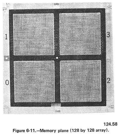
A representative core matrix (core plane or memory plane) used in several Navy computers is shown in figure 6-11. The board is a 128 x 128 array arranged in four 64 x 64 matrices and provides 16,384 one-bit storage addresses. As previously indicated, word lengths of any number of bits desired may be attained merely by stacking the memory planes one on top of the other and properly interconnecting them. For increased memory capacity and/or more efficient utilization of space within the computer, additional memory stacks may also be incorporated, provided they are properly interconnected.
READOUT
A simplified version of a memory stack consisting of seven memory planes is depicted in figure 6-12. It is assumed that the "X" and "Y" drive lines are pulsed to readout data previously stored in the cores located at the intersection of the drive lines. The sense lines read the data from each of the cores simultaneously so that the entire output (top to bottom 1101101) is read in one bit time (parallel). Also, with some circuit modifications the data can be read serially-one bit of the word in each of seven bit times. In operation one memory plane exists for each bit in the word.
The sense output is amplified and sent to specified registers where it enters into certain arithmetic or other types of operations. Reviewing briefly, the drive pulse drives from a zero to a one during the write cycle and from a one to zero during the read cycle.
The X drive pulse and the Y drive pulse are each equal to 1 /2 Hm Two pulses are required simultaneously to either set or reset the core. This action is called the coincident pulse type of operation of magnetic core memories.
The selection of a particular Y drive line and X drive line will select a particular core, and this in effect is its address.
Figure 6-13 presents in simplified form a block diagram of the circuits utilized by a representative computer to read data into and out of core memory. These circuits consist of a 15-bit memory address (S) register and translator, a data buffer (Z) register, group selectors, line selectors, inhibit selectors, and sense circuits.
[ The following discusses X,Y drive circuit reduction techniques and is not central to understand the operation of core memory]
The S translator translates the outputs from the S register to specify the unique enables that select the X and Y drive lines and inhibit lines. The S translator is enabled by setting either the read or write flip-flop in memory control. The S translator is divided into seven sections and when enabled will make the following translations:1. X primary selector S13,S14 2. X secondary selector S06,S07,S08 3. X line selector S09,S1O,S11 4. Y primary selector S12,S14 5. Y secondary selector SOO,SOl,S02 6. Y line selector S03,S04,S05 7. Inhibit selector S12,S13,S14The X primary selector is a group of circuits which select and enable the primary windings of one of four X selectors (drive current transformers). Note: For the purpose of simplifying this discussion the primaries of the drive current transformers are treated as a single winding. The drive current transformers, in fact, have two primaries, one for read and one for write. Thus, for proper primary selection there must be eight primary selectors. (Both the set and clear outputs of S13 and S14 are utilized to make the proper selection.)When the read or write pulse appears, it will drive the primary of the selected transformer. This induces a current in the transformer's secondaries which, depending on the secondary selection, is applied to groups of interconnected X drive lines.
The X secondary selector is a group of circuits which select and enable one of the eight secondary windings of the selected drive current transformer. The secondaries of the unselected transformers are isolated from selection by diodes.
The X drive line selector is a group of circuits which select and enable one of the eight drive lines selected by the X secondary selector. Unselected drive lines are isolated from selection by diodes.
When the X primary, secondary, and line selector enables are all present, memory control initiates the read and write pulses in the selected transformer primaries. The pulses are then coupled through the selected secondary to the selected X drive-line. The selected drive line is threaded through cores occupying the same relative position on each of the memory planes comprising a given memory stack. Before selection of a specific core in the corresponding quadrants of each of the memory planes, the Y drive line concerned must also be enabled.
The Y primary, secondary, and line selectors function in the same manner as the corresponding X selectors. The primary difference between X and Y translations is in the stages of the S register and translator utilized to make the translations.
When a Y drive line is enabled, it will always intersect the selected X drive line at the same point on each of the memory planes in a memory stack. The cores at the intersections of the selected drive lines will then be driven to their 0-state by a read pulse or to their I-state by a write pulse, providing (1) they are not already in a 0-state during the read cycle, or (2) an inhibit pulse does not appear coincident with the write pulse during a write cycle.
The inhibit selector is a group of circuits that select and enable the inhibit windings in the quadrant where the selected X and Y drive lines intersect on each of the memory planes in the memory stack. If an inhibit is required during a write cycle, current will flow through the enabled inhibit lines.
The generation of the inhibit pulse is a function of the Z register. If 0 is to be written into memory (Z_=0), an inhibit pulse will be generated which will prevent a 1 from being written into the corresponding bit position in the addressed memory location. Note: Although an inhibit may not be required, all inhibit lines (one for each quadrant of each core plane) are enabled prior to a read/write cycle by setting the inhibit flip- flop in memory control.
The sense circuits connect the outputs from the memory planes to the Z register. Each sense circuit connects the outputs from the eight sense windings in a bit-plane (two memory planes) to a stage in the sense register. The sense register, in turn, connects to the Z register.
The input to each sense amplifier is from diagonally opposite sense windings on a memory plane. The strobe pulse is applied as an enable to the Z register. The strobe pulse appears approximately 0.3 microsecond after the start of the read pulse, and, being only about 0.2 microsecond wide, will gate the output from the core into the Z register at a time when this output is at maximum amplitude (a logic 1).
The use of magnetic cores as described provides high-speed, random-access, nonvolatile storage. A storage component is considered nonvolatile if it retains its binary state when all power is removed from the equipment. The term high-speed memory is defined relative to the time required to gain access to data in memory when other types of storage elements such as magnetic drums or tape are used. It may be defined in terms of the shortest access time of two or more systems which use the same type of storage element. In all cases, the term "high- speed" is relative.
Return to On Line Documents