A Translation Routine for the DEUCE Computer
by R. C. Brigham and C. G. Bell
INTRODUCTION TO THE PROBLEMSummary: Most computers in operation today have supplementary programs which do automatic coding or program assembling. These programs either translate, automatically code, or interpret pseudo instructions which in themselves may cause the enaction of hundreds of actual machine instructions. The outstanding feature of such routines is that programming time and effort is cut to a minimum.This paper deals generally with translation and interpretive schemes, and specifically with a suitable translation routine for use with the DEUCE computer. The translation program is called SODA, or Symbolic Optimum Deuce Assembly Program. Two examples of SODA use are included in an appendix.
DEUCE is a two-plus-one-address computer having twelve 32-word mercury delay lines of rapid-access storage, and an 8,192-word magnetic drum backing store (see Haley, 1956). It has proved to be a powerful tool for both scientific and commercial applications, and its usefulness is greatly increased by a large library of subroutines and programs. The cost of the machine places it in the medium-scale computer class, but the speed of operation is comparable to machines in the large-scale class. Certain aspects of programming DEUCE, however, are clerical in nature, and can be somewhat tedious; such programming work might well be left td the machine itself.
The object of the work leading to this paper has been the development of a programming scheme which makes the writing down of a program much simpler and more straightforward than normal DEUCE programming. This is because the SODA language is closer to that of a mathematical language, and includes strong mnemonic aids. Any sort of intermediate routine which eases the programmer's work is especially of value in an academic environment. Universities tend to have a great number of problems which necessitate the use of a computer, but do not have the necessary programming staff to write the programs. A system such as SODA enables people who are familiar with a problem, and who are not familiar with computers, to write their own programs with relatively little external assistance.
The basic difficulties in preparing a program for any machine can be minimized by the use of either interpretive or translation routines. Almost all computers in use today have routines of this nature available simply for the ease, efficiency, and convenience of the user. Even though these "intermediate" routines generally require more machine time, the aid they give the programmer (particularly a novice) makes them highly desirable from an economic point of view.
INTERPRETIVE AND TRANSLATION ROUTINES
Any intermediate automatic coding program for a computer may be broken down into either a translation or an interpretive routine. There are routines which combine the advantages of both translation and interpretive routines to give optimum results in terms of machine efficiency and programming effort. For example, some routines, in order to minimize programming time, require that a pseudo program be run through a translator, an interpreter, and then an optimizing program (in the case of computers with only a drum or delay-line store), before giving a coded program in machine language, suitable for the actual solution of the problem.
An interpretive routine is a program which, when given an order (which is called a pseudo order) in a simplified language, calls in (i.e. transfers control to) an appropriate subsequence, stored elsewhere in the machine, to carry out that step in the calculation. After completion of the subsequence, control returns to the interpretation of the next pseudo instruction. An interpretive routine most useful for the DEUCE machine is called the General Interpretive Program (GIP). GIP, designed for handling almost any matrix manipulation, also enables the programmer to operate on large blocks of data in a prescribed sequence. Another similar but less elaborate interpretive routine for the DEUCE is the Tabular Interpretive Program (TIP). Still another interpretive program is called Alphacode; this is an alpha-numeric system which transforms the computer into a three-address machine which has indexing facilities and works entirely in floating-point arithmetic. These three routines were described by Robinson (1959).
When using a translation routine, the program is first written down in terms of the pseudo orders of the translator's vocabulary, which is similar to that of an interpretive routine. These pseudo orders, however, are then fed into the translator, which produces an output program in terms of standard machine orders. It is this program, in the standard computer language, which effects the problem solution. The interpretation of the pseudo orders thus occurs only once. Since interpretation usually consumes considerable machine time, a translation scheme is of most advantage with often-used programs. It is believed that SODA is the first translation scheme prepared for DEUCE.
INTRODUCTION TO THE NEW PSEUDO LANGUAGE SODA
The purpose of SODA is to make the writing down of instructions for DEUCE easier. In doing this, certain physical features of DEUCE, which may make programming somewhat tedious in the DEUCE language, have to be overcome. These problems are, in general, those that face the writer of a translation routine for a computer which has a limited amount of non-randomaccess storage, and another larger level of backing storage.
Eight of DEUCE's twelve mercury delay-lines are connected to the control unit of the machine so that only these eight can contain the program. For programs larger than 8 x 32 instructions, more program must be brought into delay lines from the magnetic drum at the proper time. The drum contains 256 32-word tracks numbered 0 to 255. SODA makes it possible for the programmer to assume that almost the entire drum is a random-access store that handles both data and program. Since either data or program is automatically brought into delay lines only when needed, this means that SODA defines a machine with only one level of storage.
When programming in the DEUCE language, the programmer usually aims at coding the program within the delay lines in an optimum manner such that the next instruction word is available at the same time that the previous order is completed. Very poor coding can result in an increase in the running time of up to several times that of an optimally coded program. SODA writes orders in terms of DEUCE instructions, and optimization is automatically done in every group of delay lines of instructions. Up to 192 DEUCE instructions, optimally coded within every set of two delay lines, may be in any group, but the programmer is not faced with the size of groups, or when and where each begins, as the transfer from one group to the next is carried out automatically.
All necessary subroutines are also placed in the mercury store when a new group, or block, of instructions is brought from the drum. The new information is transferred one delay line immediately following another, a process requiring at least 13 milliseconds per delay line. It is possible that a repetitive loop in the SODA program could result in the transfer of two or more blocks of DEUCE instructions to the fast store each cycle, thereby greatly reducing the efficiency of the translated program.
The more experienced SODA programmer can compensate for this to a certain extent by placing what is known as a "LOOP" control card before repetitive portions of the SODA program. Associated with each SODA operation are a specified number of DEUCE instructions. The programmer can sum the numbers associated with the SODA instructions in the loop and include the sum as a parameter of the control card. If possible, the translation process will then place the loop within a single group of DEUCE instructions. Thus, in Example 1 of Appendix 2, instructions 11-14 comprise a repetitive loop which one would desire to have as fast as possible. Therefore, a "LOOP" control card might well be inserted between instructions 10 and 11.
Each DEUCE instruction must include six numbers which specify various addresses and clock times of the computer. This detail, which is attributable to the logical layout of the DEUCE hardware and insures optimum coding, discourages people who do not have time to learn the process. SODA alleviates the problem by defining a more conventional computer with less hardware; the book-keeping details of programming are therefore lessened.
Another factor to which a novice must become acclimatized is that the DEUCE machine operates in binary arithmetic. There are a host of subroutines available for decimal input and output, but the details of using them are a bit involved for the inexperienced user. Although SODA operates internally either in binary or standard floating-binary form, there are pseudo instructions available which permit either binary, decimal, or floating-decimal input and output.
SODA is a one-plus-one-address "machine," recognizing either numeric or mnemonic orders which bear no resemblance to the DEUCE instruction format, and whose addresses may be written with symbolic names. It is therefore the purpose of SODA to translate to DEUCE language from a language more easily understood by the occasional user who has not had previous computer experience, that is, from a simple language which is quite close to that found in writing a step-bystep word statement of a mathematical calculation. Existing DEUCE subroutines may be used with SODA by employing a "SUBROUTINE" control card. This card associates with the subroutine a mnemonic reference in standard SODA terminology. Once the control card has been supplied to the translator, this mnemonic reference can be given at any point in the SODA program, just as if it were a regular SODA instruction, whenever it is desired to employ the subroutine.
THE SODA MACHINE AND THE SODA LANGUAGE
The selection of a pseudo language rests on many requirements, the most important of which are the ease with which the language can be used, and the efficiency of the final machine program. Other points of consideration include the ease with which the translation program itself can be written, and the more pressing requirements of the computation laboratory sponsoring the development.
The first point argues for a language close to that which the human user employs as his own language. Thus we might desire to write algebraic equations, or merely give sentence statements of what is desired. The former of these is presently receiving some attention by Dr. C. Hamblin of the Humanities Department of the University of New South Wales, Sydney, Australia. He has already written an interpretive program using such a language. A translation program for this type of language is extremely involved, and it was felt that something which would be available quickly would be more desirable. In addition, it was felt that at a university it would be advantageous to have a language which was more like that of a conventional single-address machine. Once such a language is mastered, the step towards programming any machine, including DEUCE, is a relatively minor one. The choice for a language, therefore, embodies the principles employed in programming a more conventional type computer, with the additional facility that the instruction names and the various addresses can be alphabetical in nature, thereby allowing for mnemonic aids. Indeed, SODA incorporates many of the features employed in SOAP (Symbolic Optimum Assembly Program) for the IBM 650 computer and SAP (Share Assembly Program) for the IBM 704 machine. The basic language of these same two schemes was used as a guide throughout the development.
SODA transforms DEUCE so that it resembles, to the programmer, the computer illustrated in Fig. 1. Those familiar with DEUCE logic will notice many differences between the two machines. It is one of the difficult aspects of writing a translation program to think of two entirely separate machines, one being the actual computer and one the pseudo computer defined by the language.
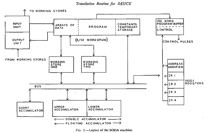
The difference from the DEUCE machine is immediately apparent. Here the memory is composed exclusively of a 256-track drum divided between program, constants, and temporary storage in the first part, and data in the second. The dividing line between data, program, and constants is not fixed, and the only requirement is that the program does not overlap any of the data area, which has been defined at the beginning of the SODA program.
There is a direct connection between the part of the memory devoted to constants and temporary storage, and the bus. Data in the second part of the drum memory are arranged in what are termed arrays, each with a symbolic name, and the programmer can get at them only by placing them in one of the two working stores, which can be considered as random-access memories of indefinite size. When working with data in the working stores, it is possible to step through the data by employing index registers. A particular element in an array can be selected by counting back from the last element a number of elements equal to the number in a specified index register. Thus, the last element is chosen if the index register contains a nought, the next to last if it contains a one, and so forth. There is a path between the index registers and the bus, so they can be loaded or their contents stored away, and a special adder/comparison unit is included, so they can be both modified and examined. Any element of an array can be given a spot numeric reference without the use of index registers. If the programmer has finished with an array in one of the working stores, and he has placed information in it which must be retained, then he must return the array to the drum. A special SODA instruction is provided for this purpose.
The arithmetic unit is composed of three accumulators (short, upper and lower), each of which has all the facilities of a normal accumulator except that multiplication and division are limited to the upper. Furthermore, the upper and lower have the facility of combining into a double-length accumulator which is capable of performing addition, subtraction, and a limited number of other double-length operations.
The lower and upper also form a floating accumulator which permits floatingpoint operations. In this pseudo computer, control extracts the instructions from the program memory, in the correct sequence, and interprets them so that the stated requirements are transacted. Finally, the input and output correspond to either binary, decimal, or floating-decimal read and punch. When blocks of binary information are employed, there is a sum check on data coming in to the machine, and a check sum is computed for output punching. No other data checks are included in the first version of SODA. The input and output arrangements of binary arrays will not, in general, match the existing card conventions on DEUCE. However, if the array can be considered as a single-row matrix, then the data will be in conventional DEUCE form except for the data card preceding the matrix, and this could be incorporated by the SODA program if desired. Indeed, the programmer can always employ SODA to produce conventional form at the expense of added SODA instructions.
It is difficult to discuss the SODA machine and the SODA language separately since, as is true in any real computer, there is a correspondence of the first order between the two. The machine described above lends itself most easily to a single-address type of code. It is felt by many that a three-address code is actually quite a bit easier to use and for the novice programmer to understand. The three-address code is certainly more efficient for certain types of problems. Nevertheless, as was mentioned above, it was desired that the resultant program be usable as an introduction to computer programming, and the single-address system allies itself more closely with the vast majority of computers presently in existence.
The SODA code is a modified single-address one in that provision for specifying the location of the next instruction is included. This was done because it seemed to ease some of the problems of writing the translation program, without affecting the basic single-address principles.
One pseudo instruction is punched per input card, and occupies the first 25 columns of the normal 32-column DEUCE field. The cards are punched in standard alphanumeric form.
Five control (or directive) cards assist in the organization of the translated program. Three of these are used at the beginning of the SODA program. These direct the initializing before the actual program is translated. The first type defines the names of all constants or temporary storage spaces used in the SODA program. A name may be up to five characters in length, at least one of which must have a hole punched in the Y or X row. The second type defines any subroutines used in the program, and is the "SUBROUTINE" control mentioned above. The third type reserves space for any data that are to be stored as an array or block, and is used by stating the number of the last track holding elements in the array, the number of elements in the array, and the name by which the array will be specified. Still another type of control instruction defines the starting point of the pseudo program, and it follows the last card of the program being translated. The fifth control card is the "LOOP" control described above.
The basic SODA instruction is composed of four parts: the location of this instruction, the operation, the location of the operand, and the location of the next instruction. The location of this instruction is composed of five punched columns representing the address by which the instruction is to be known. These columns may be left blank, in which case it is assumed that this instruction is to be obeyed immediately after the preceding one. The only reason for having a symbolic name in these columns is to provide an initial point for the first instruction, or to provide a name to which a jump reference can be made.
The operation is three characters in length, and is essentially a mnemonic abbreviation to remind the programmer of the operation. A list of the instructions is given in Appendix 1. A version of SODA exists which provides a list of numeric instructions. This is useful when alpha-numeric auxiliary equipment is not available.
The location of the operand is five characters in length. These columns may be symbolic, numeric, or blank. The operand is the actual number corresponding to the operand address. The symbolic address either refers to a constant (defined by the initializing control card giving the names of the constants) or to an array of data which has been placed in one of the working stores. If the operand address is numeric, 0-31 refers to one of 32 physical positions in working store one, 32-63 refers to working store two, 64-95 refers to constants store, 100 is the short accumulator, 101 is the lower accumulator, 102 is the upper accumulator, and 103-107 refer to special binary numbers. In addition to these conditions, a symbolic address, when used with one of the conditional jump instructions, may specify the location to which the jump is addressed.
The location of the next instruction is composed of five characters. This address is usually left blank, which assumes that the next instruction to be obeyed follows on the succeeding card. When conditional branching instructions are used, the operand location and the location of the next instruction describe the two alternative paths which the jump selects, the former being taken if the jump condition is fulfilled.
In addition to these basic specifications, various other quantities may be included in the SODA instruction. For many of the orders one column may give the number of the index register used in the instruction.
Index registers, it will be recalled, are used with arrays of data, and the element of the array is selected according to the contents of the index register. Five columns are used with three special conditional jump instructions, and are labelled the decrement. The decrement is used as a comparison for jumps involving the index registers, or as an operand in modifying the contents of an index register. The instructions using a decrement are marked with an asterisk in Appendix 1, Section G. As illustration, in Example 1, instruction 11 is labelled "LOOP." It places in the upper accumulator one element of array A (defined by card l, an array definition control card). The particular element selected depends upon the number in index register 1. Instruction 14 causes the decrement (here 1) to be subtracted from index register I. If the result is positive, control returns to instruction 11. If the result is negative, instruction 15 is obeyed next.
THE USE OF SODA
SODA instructions are written down directly from a detailed flow diagram. They are then punched (one per card) and the cards fed into the machine under the control of the translation routine. The SODA instructions are translated at approximately seventeen per minute. The output of the translator is a pack of cards punched with a program written in terms of DEUCE instructions. This pack is placed behind a standard pack of cards, and the program is then ready to run.
CHECKING THE TRANSLATED PROGRAM
During the translation, a trace (or program-testing) facility may be built into the machine program by setting a non-zero number on the input keys. Inclusion of the trace does not mean that the facility must be used during the running of the final machine program. During the running of the machine program, the trace may be operated in any of three modes. If a negative number is placed on the input keys, each SODA instruction obeyed will punch out the contents of the accumulators and index registers, together with an identification number of the instruction just enacted. If a non-zero positive number is set on the keys the program will stop after each instruction, with an identification of the number of the operation on the output lights. The various stores may then be examined on an associated cathode-ray tube. Zero on the input keys causes the trace facility to be by-passed, and the program runs without stopping (except for programmed stops). When the final program has been completely checked, it may be run either by this by-passing of the trace feature, or by re-translation without inclusion of the trace. The latter will result in a faster program.
RESULTS
SODA has successfully translated many programs. Reports from the programmers indicate a substantial time saving over normal DEUCE programming, and they feel that this will increase as familiarity with SODA grows. The scheme still includes many programming details that would not occur in the ideal system. Most of these result from compromises due to the difficulty of eliminating them in the available time. Nevertheless, SODA users do indicate an appreciable reduction in the overall programming burden.
SODA produces a less efficient program than could be written by hand, the decreased efficiency arising from two main sources. First, a DEUCE program written by SODA contains many more instructions than the equivalent hand-written program. Secondly, calculations do not occur simultaneously with the transfer of information between the drum and the mercury store. Simultaneous computation is possible in normal DEUCE programming. Both effects are a result of inability to simulate easily the subtleties inherent in human programming. Nevertheless, the authors feel that the savings in human labour will more than compensate for the slightly decreased efficiency of the final DEUCE program.
ACKNOWLEDGEMENTS
The authors are deeply indebted to Professor R. E. Vowels and the Electrical Engineering Department of the University of New South Wales for making this research possible. Specifically we would like to thank Mr. R. G. Smart, Senior Lecturer in charge of the UTECOM Computing Laboratory, for assisting with various details of the SODA program, and for making machine time available at UTECOM. We especially wish to express gratitude to Mr. George Karoly who helped write various portions of SODA, "ironed out" sundry troublesome details, and provided general encouragement throughout the development. Lastly, we would like to thank the Staff at the University and UTECOM for the assistance in preparing programs for the machine.
Mr. R. C. Brigham is now (July 1959) with the Martin Company, Orlando, Florida, and Mr. C. G. Bell is at Speech Communications Laboratory, Massachusetts Institute of Technology, Cambridge, Mass., U.S.A.
APPENDIX 1
LIST OF SODA INSTRUCTIONS
B. Instructions Pertaining to the Lower Accumulator
C. Instructions Pertaining to the Upper Accumulator
D. Instructions Pertaining to the Double Accumulator
E. Instructions Pertaining to Floating-point Arithmetic
F. Instructions Pertaining to the Index Registers
G. Decision or Conditional Jump Instructions
H. Instructions Involving the Working Stores
l. Instructions Pertaining to Input and Output
J. Miscellaneous Instructions
EXAMPLES OF SODA PROGRAMMING
Example 1-Vector Dot Product:
Coding:
| Card number | Punching | Comments |
| 1 | 3, A- -, 255, 1024 | Array A is defined. Its last track on the drum is 255; it has a maximum of 1024 elements (32 tracks). |
| 2 | 3, B-----, 223, 1024 | Array B is similarly defined. Its last track is track 223; it too has a maximum of 1024 elements. |
The regular SODA program is:
| Card number | Location of this instruction | Opera- tion | Operand Address | Location of next instruction | Index Register | Decrement | Comments
| 3
| BEGIN
| RDC
| 00000
|
|
|
| n in index register units is read into
location 00000.
| 4
|
| LXP
| 00000
|
| 1
|
| Index register (IR) 1 is made equal to n.
| 5
|
| RDA
| A-----
|
|
|
| Vector A is read to the drum. The number
of elements read is equal to the number in IR 1.
| 6
|
| RDA
| B-----
|
|
|
| Vector B is read to the drum, again according
to the number in IR 1.
| 7
|
| RWO
| A------
|
|
|
| A is placed in working store one.
| 8
|
| RWT
| B----
|
|
|
| B is placed in working store two.
| 9
|
| STZ
| 00100
|
|
|
| Short accumulator (which has operand address code
number 100) is set to zero.
| 10
|
| SBX
| 00104
| LOOP-
| 1
|
| I is subtracted from IR 1. Operand address of 104 indicates a 1 in IR units.
| 11
| LOOP-
| CAU
| A--
|
| l
|
| A is placed in upper. IR l selects a particular element of array A.
| 12
|
| MPY
| B ---
|
| 1
|
| Aj x Bj formed.
| 13
|
| ADS
| 00102
|
|
|
| The product (in upper, designated as 102) added to
partial sum in short.
| 14
|
| JIX
| LOOP--
|
| 1
| 00001
| 1 is subtracted from IR l. Jump is made to instruction
if result is negative. Otherwise control is
returned to instruction 11.
| 15
|
| STS
| 00064
|
|
|
| Answer stored in location 64.
| 16
|
| PHC
| 00064
| BEGIN
|
|
| The answer is punched; control returns to beginning.
| |
| Card number | Punching | Comments |
| 17 | 1, BEGIN | This is known as a type 1 control. It specifies the address of the first instruction to be obeyed. Here the first one is "BEGIN," associated with instruction 3. |
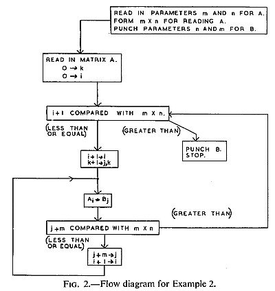
Example 2-Transpose an m by n Matrix:
|
|
The regular SODA program is:
| Card number | Location of this instruction | Opera- tion | Operand Address | Location of next instruction | Index Register | Decrement | Comments
| 8
| START
| RDC
| 00000
|
|
|
| Parameter card for matrix AMN. m goes to location 00000,
n to 00001. m and n are in IR units.
| 9
|
| CAU
| 00001
|
|
|
| n is placed in the upper.
| 10
|
| CAS
| 00000
|
|
|
| m is placed in the short.
| 11
|
| STU
| 00000
|
|
|
| The two parameters m and n are interchanged. The parameter card
| 12
|
| STS
| 00001
|
|
|
| for BNM (matrix B) will be punched before the matrix.
| 13
|
| STS
| MM---
|
|
|
| m stored for future use.
| 14
|
| MPY
| MM---
|
|
|
| m x n .formed. (Because n is in the upper.)
| 15
|
| SUL
| 00016
|
|
|
| The upper is shifted left 16 places. This is necessary
because of the details of multiplication.
| 16
|
| STU
| MN---
|
|
|
| m x n is stored.
| 17
|
| PHC
| 00000
|
|
|
| Parameter card for BNM punched.
| 18
|
| LXP
| MN----
|
| 1
|
| IR 1 loaded with m x n for reading AMN to the drum.
When reading to or punching from drum, IR 1 states the
number of elements in the array.
| 19
|
| RDA
| AMN--
|
|
|
| Matrix AMN (matrix A) read to drum.
| 20
|
| RWO
| AMN----
|
|
|
| AMN placed in working store 1.
| 21
|
| RWT
| BNM --
|
|
|
| BNM placed in working store 2. This is necessary even
though no information is yet in BNM.
| 22
|
| LXP
| MN-- -
| TRANS
| 2
|
| IR 2 set with m x n for reading elements of AMN.
| 23
| TRANS
| JIX
|
| END--
| 2
| 00001
| l is subtracted from IR 2. Transpose is completed if result is negative. An IR containing
mn - i elements will select the ith element of an array of mn elements.
| 24
|
| LXP
| MN-- --
|
| 3
|
| IR 3 set with m x n for storing elements of BNM.
| 25
|
| SBX
| 00104
|
| 3
|
| 1 (code 104) is subtracted from IR 3. Instructions 24
and 25 could be replaced by the single operation LXL.
| 26
|
| STX
| MN-- --
| LOOP-
| 3
|
| Results stored as new value in location MN.
| 27
| LOOP-
| CAS
| AMN--
|
| 2
|
| The elements of AM N are taken and stored as the elements of BNM,
| 28
|
| STS
| BNM--
|
| 3
|
| according to the specified index registers.
| 29
|
| JIX
|
| TRANS
| 3
| MM---
| Index for BNM decreased by the number in location MM. It is seen that a symbolic decrement may be specified.
| 30
|
| SBX
| 00104
| LOOP-
| 2
|
| Index for AMN decreased by 1.
| 31
| END---
| WWT
| BNM-----
|
|
|
| BNM returned to the drum from working store 2 so that it may be punched from the drum.
| 32
|
| PHA
| BNM--
|
|
|
| Matrix BNM is punched. The correct number of elements
is still in IR 1.
| 33
|
| STP
|
|
|
|
| Stop. The transpose program is completed.
| |
| Card number | Punching | Comments |
| 34 | 1, START | The program obeys instruction 8 first. |
REFERENCES
- ADAMS, C. W. (1952). "Small Problems on Large Computers," Proceedings ofJoint ACM/Mellon Institute Conference, May 2-3, 1952, Richard Rimbach Associates, Pittsburgh 12, Pennsylvania.
- BELL, C. G., and BRIGHAM, R. C. (1958). SODA Manual of Operation, School of Electrical Engineering, University of New South Wales, Sydney, N.S.W., Australia.
- HALEY, A. C. D. (1956). "DEUCE: a High-speed General-purpose Computer," Proc. I.E.E., Vol. 103, Part B, Supplement No. 2, p. 165.
- HAMBLI N, C. L. (1958). "GEORGE, A Semi-translation Programming Scheme for DEUCE," Programming and Operation Manual, School of Humanities, University of New South Wales, Kensington, N.S.W.; Australia. ROBINSON, C. (1959). ' DEUCE Interpretive Programs," Computer Journal, Vol. 1, p. 172.
UNWIN BROTHERS LIMITED. WOKING AND LONDON