Return to On-Line-Documents

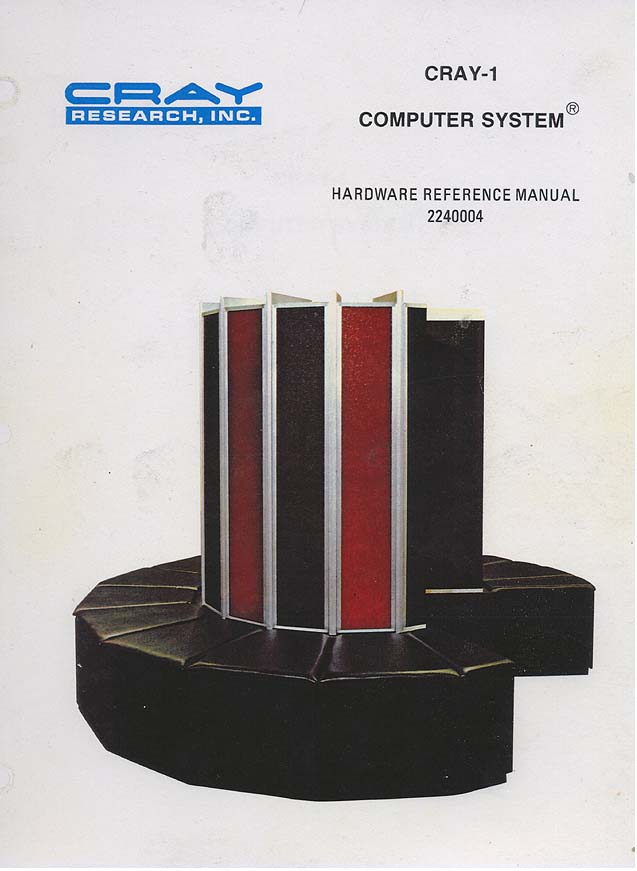
CRAY-1
COMPUTER SYSTEM®
HARDWARE REFERENCE MANUAL
2240004
Copyright©1977 by CRAY RESEARCH, INC. This manual or parts thereof may
not be reproduced in any form without permission of CRAY RESEARCH, INC.

RECORD OF REVISION PUBLICATION NUMBER
Revision Print Date Description 1/76 Original printing A 5/76 Reprint with revision A-01 9/76 Corrections to pages 3-20, 3-27, 4-9, 4-10, 4-28, 4-36, 4-43, 4-55, and 4-57. B 10/76 Reprint with revision. Addition of: Floating point range error detection Vector floating point error Error correction B-01 2/77 Changes to exchange package (p 3-36); additions to instructions 152 and 153 (p 4-53); corrections to syndrome bit description p 5-5; corrections to instruction summary, appendix D. B-02 7/77 Corrections and changes to pages xi, 2-3, 3-19 through 3-28.1, 3-31, 3-34, 3-36, 3-38, 4-14 through 4-17, 4-54, 4-68, 5-1, 5-3, 5-4, 5-6, 6-2, A-4, D-1 through D-4. C 11/77 This printing obsoletes revision B. Features added include 8-bank phasing and I/0 master clear procedure. Chart tape reflects only changes introduced with this revision.
Each time this manual is revised and reprinted, all changes issued against the previous version in the form of change packets are incorporated into the new version and the new version is assigned an alphabetic level. Between reprints, changes may be issued against the current version in the form of change packets. Each change packet is assigned a numeric designator starting with 01 for each new revision level. Every page changed by a reprint or by a change packet has the revision level and change packet number in the lower right- hand corner. All changes are noted by a change bar along the margin of the page. Requests for copies of CRAY RESEARCH, INC. publications should be directed to: CRAY RESEARCH, INC. 7850 Metro Parkway Suite 213 Bloomington, MN 55420
CONTENTS