Go To Table of Contents
| BRL 1964, UNIVAC 422 TRNG COMP, starting page 0266
|
UNIVAC 422 TRNG COMP
MANUFACTURER
UNIVAC Division of Sperry Rand Corp. St Paul, Minn.
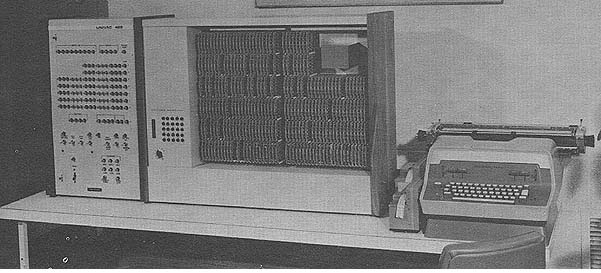 Photo by UNIVAC Division of Sperry Rand Corp.
APPLICATIONS
A computer designed and packaged for training purposes.
Applications are schools, colleges, vocational training
centers.
PROGRAMMING AND NUMERICAL SYSTEM
Internal number system Binary
Binary digits/word 15
Binary digits/instruction 15
Instructions/word 1
Instructions decoded 61
Arithmetic system Fixed point
Instruction type One address
Number range Each word sign plus 213- 1
Instruction word format
+---------+---------+
| 6 Bits | 9 Bits |
+---------+---------+
| OP Code | Operand |
+---------+---------+
Registers and B-Boxes
One B-box in core memory address zero.
ARITHMETIC UNIT
Incl. Stor. Access
Microsec
Add 9.6
Mult 24 - 46.4
Div 45.6
Construction (Arithmetic unit only)
Vacuum-Tubes 0
Transistors 1,000
Condensers 700
Diodes 4,000
Magnetic Cores 512-15 bit word core memory
Arithmetic mode Parallel
Timing Synchronous
Operation Sequential
STORAGE
No. of No. of Access
Medium Words Digits Microsec
Core 512 15 1.4
Photo by UNIVAC Division of Sperry Rand Corp.
APPLICATIONS
A computer designed and packaged for training purposes.
Applications are schools, colleges, vocational training
centers.
PROGRAMMING AND NUMERICAL SYSTEM
Internal number system Binary
Binary digits/word 15
Binary digits/instruction 15
Instructions/word 1
Instructions decoded 61
Arithmetic system Fixed point
Instruction type One address
Number range Each word sign plus 213- 1
Instruction word format
+---------+---------+
| 6 Bits | 9 Bits |
+---------+---------+
| OP Code | Operand |
+---------+---------+
Registers and B-Boxes
One B-box in core memory address zero.
ARITHMETIC UNIT
Incl. Stor. Access
Microsec
Add 9.6
Mult 24 - 46.4
Div 45.6
Construction (Arithmetic unit only)
Vacuum-Tubes 0
Transistors 1,000
Condensers 700
Diodes 4,000
Magnetic Cores 512-15 bit word core memory
Arithmetic mode Parallel
Timing Synchronous
Operation Sequential
STORAGE
No. of No. of Access
Medium Words Digits Microsec
Core 512 15 1.4
| BRL 1964, UNIVAC 422 TRNG COMP, starting page 0267
|
    INPUT
     Medium            Speed
    Paper Tape      20 chars/sec (6 level)
    Typewriter        manual (Fieldata code)
    Control Panel     manual

    OUTPUT
    Medium             Speed
    Paper Tape      20 chars/sec (6 level)
    Typewriter      10 chars/sec (Fieldata code)
    Control panel    manual
    Input/Output are under program control.

    CIRCUIT ELEMENTS OF ENTIRE SYSTEM
      Type             Quantity
    Tubes                   0
    Diodes              4,639
    Transistors         1,176
    Magnetic Cores        512-15 bit words
              4.8 microsec read-write cycle.

    CHECKING FEATURES
    A built in card tester is provided.

       POWER, SPACE, WEIGHT, AND SITE PREPARATION
    Power, computer 1.13 Kw       1.26 Kva  0.9 pf
     115 VAC, 50 or 60 cycles/second
    Volume, computer   11.5 cu ft
    Area, computer     5.25 sq ft
    Floor loading     57 lbs/sq ft
    Weight, computer  300 lbs
    Site preparation requirements
    One 115 VAC 50 or 60 cycles/second receptacle must be available.
    Air conditioning is not required.

    PRODUCTION RECORD
    Time required for delivery              3 months

    PERSONNEL REQUIREMENTS

    One operator is required.

    A service manual provided which includes a general description,
    principles of operation, operation, maintenance, installation, spare
    Parts List, and a Functional and Electrical Schematics Section.

   ADDITIONAL FEATURES AND REMARKS

    The UNIVAC 422 has a large repertoire of instructions (61) and has
    all the features of a large general-purpose stored-program computer.

    No special cooling is required. No special installation is required.
    Power is provided via a 115 VAC 50 or 60 cps outlet.

    All arithmetic, control, and I/0 registers are displayed.

    Magnetic Core storage of 512 word capacity is provided. Cycle time is
    6 microseconds. Access time is 1.25 microseconds.

    The UNIVAC 422 has been designed to meet the needs of both classroom
    and laboratory.

    For classroom use, a group of students can observe the registers and
    controls of the machine, and can learn proper operating procedures.
    All logical elements are exposed, permitting the instructor to
    demonstrate the functions of the individual circuits.

    In the laboratory, two or three students may be assigned to the same
    machine at one time, yielding a high-use factor and increasing the
    amount of actual machine time given to each student.
| BRL 1964, UNIVAC 1000, starting page 0268
|
UNIVAC 1000
MANUFACTURER
UNIVAC, Division of Sperry Rand Corp., St Paul, Minn.
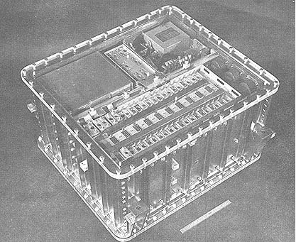 Photo by UNIVAC, Division of Sperry Rand Corp.
APPLICATIONS
Missile Inertial Guidance (checkout, targeting, and calibration,
using explicit, implicit, delta minimum, path adaptive, etc
methods). Navigation (missile and aircraft) Spacecraft (manned and
unmanned) Command & Control Process Control (Real Time) Fire Control
Mobile Unit Command & Control (helicopter, orbital, hydrafoil,
missile, aircraft). Data Processing (ASW, ECM, telemetry, data link)
Flight Control & Adaptive Flight Control
PROGRAMMING AND NUMERICAL SYSTEM
Internal number system Binary
Binary digits/word 24
Binary digits/instruction 24
Instructions/word 7
Instructions decoded 1,024
Arithmetic system Fixed point (fractional)
Instruction type One address
Limited selectable other operand.
Number Range + 1 to - 1
Instruction word format
+-----+-----------+-----------+---------+----------+
| 0 | 1 3 | 4 7 | 8 10 | 11 23 |
+-----+-----------+-----------+---------+----------+
| B | Acquire | Operation | Restore | Operand |
| Box | A, X, U | | or | Address |
| | I/0 Shift | | Test | 0-8191 |
+-----+-----------+-----------+---------+----------+
Automatic built-in subroutines
Increment +1, -1, +2
External Jump Request, and Real Time Jump Request
Automatic coding
CS-1 Assembler operates on 1206 or USQ-20 computer, 1206 and USQ-20
to ADD-1000 Code Converter, instruction simulator, open loop
guidance simulator.
Photo by UNIVAC, Division of Sperry Rand Corp.
APPLICATIONS
Missile Inertial Guidance (checkout, targeting, and calibration,
using explicit, implicit, delta minimum, path adaptive, etc
methods). Navigation (missile and aircraft) Spacecraft (manned and
unmanned) Command & Control Process Control (Real Time) Fire Control
Mobile Unit Command & Control (helicopter, orbital, hydrafoil,
missile, aircraft). Data Processing (ASW, ECM, telemetry, data link)
Flight Control & Adaptive Flight Control
PROGRAMMING AND NUMERICAL SYSTEM
Internal number system Binary
Binary digits/word 24
Binary digits/instruction 24
Instructions/word 7
Instructions decoded 1,024
Arithmetic system Fixed point (fractional)
Instruction type One address
Limited selectable other operand.
Number Range + 1 to - 1
Instruction word format
+-----+-----------+-----------+---------+----------+
| 0 | 1 3 | 4 7 | 8 10 | 11 23 |
+-----+-----------+-----------+---------+----------+
| B | Acquire | Operation | Restore | Operand |
| Box | A, X, U | | or | Address |
| | I/0 Shift | | Test | 0-8191 |
+-----+-----------+-----------+---------+----------+
Automatic built-in subroutines
Increment +1, -1, +2
External Jump Request, and Real Time Jump Request
Automatic coding
CS-1 Assembler operates on 1206 or USQ-20 computer, 1206 and USQ-20
to ADD-1000 Code Converter, instruction simulator, open loop
guidance simulator.
| BRL 1964, UNIVAC 1000, starting page 0269
|
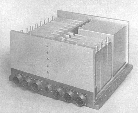 Photo by UNIVAC, Division of Sperry Rand Corp.
Registers and B-Boxes
Instruction Register Z
Arithmetic Registers M & M*
Address Registers S & P
Variable memory location usable as B-Box; variable memory
locations used as A, X, and Iteration Counter.
Use of phase field logic sequence make 1024 instruction
(2,048 B--Boxed) with only 30 operation codes.
ARITHMETIC UNIT
Incl. Stor. Access Excl. Stor. Access
Microsec Microsec
Add 6 3
Mult 410 - 711
Div 500 - 838
Multiplication and division is performed by subroutine. Times
given are for 18 to 48 bit products and 9 to 24 bit quotients.
STORAGE
No. of No. of Access
Medium Words Digits Microsec
Thin Film (Program) 6,656 24 3
Thin Film (Variable) 256 24 3
The program storage is non-destructive read-out
thin film. The variable (data) storage is destructive read-out
thin film. Magnetic tape
No. of units that can be connected 16 Units
Characteristics of the tape unit depend on whether it is an
airborne or ground system.
INPUT
Medium Speed Remarks
Accelerometer 300 microsec Incremental
Angle Optisyn Program control Gray Code
Doppler Radar Program control 24-bit Parallel data
Paper Tape Program control 6-bit Parallel
Discrete Control Program control 24-bit Parallel
Real Time 5 & 50 millisec 1,000 cycles/sec
OUTPUT
Medium Speed Remarks
Dig. to Analog Conv 12 microsec Analog
Relay Pullers 1,000 microsec Discrete 12-bit (1/2 amp)
Punch & GSE 12 microsec 6-bit
Punch & GSE 12 microsec 24-bit
    Photo by UNIVAC, Division of Sperry Rand Corp.

    Registers and B-Boxes
     Instruction Register Z
     Arithmetic Registers M & M*
     Address Registers S & P

    Variable memory location usable as B-Box; variable memory
    locations used as A, X, and Iteration Counter.

    Use of phase field logic sequence make 1024 instruction
    (2,048 B--Boxed) with only 30 operation codes.

   ARITHMETIC UNIT

              Incl. Stor. Access     Excl. Stor. Access
             Microsec                Microsec
    Add        6                        3
    Mult     410 - 711
    Div      500 - 838

    Multiplication and division is performed by subroutine. Times
    given are for 18 to 48 bit products and 9 to 24 bit quotients.

     STORAGE
                            No. of     No. of    Access
    Medium                  Words      Digits    Microsec
    Thin Film (Program)     6,656        24         3
    Thin Film (Variable)      256        24         3

    The program storage is non-destructive read-out
    thin film. The variable (data) storage is destructive read-out
    thin film. Magnetic tape
    No. of units that can be connected      16 Units
    Characteristics of the tape unit depend on whether it is an
    airborne or ground system.

    INPUT

    Medium               Speed               Remarks

    Accelerometer       300 microsec        Incremental
    Angle Optisyn       Program control      Gray Code
    Doppler Radar       Program control      24-bit Parallel data
    Paper Tape          Program control       6-bit Parallel
    Discrete Control    Program control      24-bit Parallel
    Real Time           5 & 50 millisec   1,000 cycles/sec

    OUTPUT

    Medium                        Speed     Remarks
    Dig. to Analog Conv      12 microsec     Analog
    Relay Pullers         1,000 microsec    Discrete 12-bit (1/2 amp)
    Punch & GSE            12 microsec       6-bit
    Punch & GSE            12 microsec      24-bit
| BRL 1964, UNIVAC 1000, starting page 0270
|
    CHECKING FEATURES

    Fixed checking features include separately enabled special constant
    NDRO (non-destructive read out) and program NDRO memory sections, and
    arithmetic overflow indication and test. An optical check is an
    inhibit instruction execution from special constant regions.

    POWER, SPACE, WEIGHT, AND SITE PREPARATION

    Power, computer         0.262 Kw 0.262 KVA 1.0 pf
    Volume, computer        1.7 cu ft
    Area, computer          2.4 sq ft
    Weight, computer       85.0 lbs
    A DC to DC Converter is used.

    Only room air conditioning as otherwise required is necessary.

    PRODUCTION RECORD

    Number produced to date       Several

   RELIABILITY, OPERATING EXPERIENCE

    The mean time between failures (MTBF) is 10,000 hours.

     ADDITIONAL FEATURES AND REMARKS

    Outstanding features include the use of silicon semiconductors,
    encapsulated welded--cordwood construction, magnetic thin-film,
    random access, electrically alterable NDRO and DRO memory, self
    contained power supply and self contained input/output.

    Other advantages are on-line self-loading of program and constants
    while computer is mounted in carrier vehicle; programmable output on
    telemetry serializer; timed interrupt and priority control circuits,
    completely random access memory with full subroutine and indexing
    capabilities.

    The computer includes analog to digital converters, incremental
    input, telemetry formating and serialization, and all missile
    interface within its weight and volume. The computer has two types of
    interrupts, one an incremental input changes the contents of any
    variable memory cell +1, -1, or i'2 on external request, the other
    will transfer program control (fixed subroutine jump) on external
    request. The computer includes a real time clock input for
    synchronization and program segmentation.


    Photo by UNIVAC, Division of Sperry Rand Corp.
| BRL 1964, UNIVAC 1000, starting page 0271
|
| BRL 1964, UNIVAC 1004 80/90, starting page 0272
|
UNIVAC 1004 80/90
UNIVAC 1004 80/90 Card Processor
MANUFACTURER
UNIVAC, Division of Sperry Rana Corp.
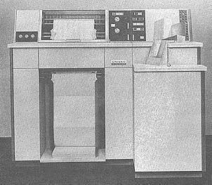 Photo by UNIVAC
APPLICATIONS
Punch card applications requiring a considerable
amount of calculation and logical decision, high-speed
printed output including a wide range of printed
formats and punch card output. For 80-Column System:
Model Numbers 1004-02 - 80 Column
1004-04 - 80 Column
1004-06 - 80 Column
1004-07 - Equipped to read 80 or
90 Column Code
For 90-Column System:
Model Numbers 1004-01 - 90 Column
1004-03 - 90 Column
1004-05 - 90 Column
1004-07 - Equipped to read 80 or
90 Column Code
PROGRAMMING AND NUMERICAL SYSTEM
Internal number system Binary coded dec.
(Excess three)
Decimal digits/word Variable
(Word length not fixed)
Arithmetic system Fixed point
Instruction type Two address
Number range Not fixed
(Limited only by available memory)
All instructions and operands are plugboard wired.
ARITHMETIC UNIT
Incl. Stor. Access Microsec
Add 6-digit sum - 128 microsec
48 microseconds for first digit in Operand 2; 16
microsec for each additional digit in Operand 2. 16
microsec for recomplementing each complementary
Photo by UNIVAC
APPLICATIONS
Punch card applications requiring a considerable
amount of calculation and logical decision, high-speed
printed output including a wide range of printed
formats and punch card output. For 80-Column System:
Model Numbers 1004-02 - 80 Column
1004-04 - 80 Column
1004-06 - 80 Column
1004-07 - Equipped to read 80 or
90 Column Code
For 90-Column System:
Model Numbers 1004-01 - 90 Column
1004-03 - 90 Column
1004-05 - 90 Column
1004-07 - Equipped to read 80 or
90 Column Code
PROGRAMMING AND NUMERICAL SYSTEM
Internal number system Binary coded dec.
(Excess three)
Decimal digits/word Variable
(Word length not fixed)
Arithmetic system Fixed point
Instruction type Two address
Number range Not fixed
(Limited only by available memory)
All instructions and operands are plugboard wired.
ARITHMETIC UNIT
Incl. Stor. Access Microsec
Add 6-digit sum - 128 microsec
48 microseconds for first digit in Operand 2; 16
microsec for each additional digit in Operand 2. 16
microsec for recomplementing each complementary
| BRL 1964, UNIVAC 1004 80/90, starting page 0273
|
 Photo by UNIVAC
character in Operand 2. 16 microsec per program step when signs of
Operands 1 and 2 are not alike.
Speeds for representative additions and subtractions are as follows:
Number of Operand 2 DigitsTime (Microsec)
8 160
10 192
20 352
See below for multiplication timing formula. Representative times
are as follows:
Number of Number of Number of Aver. Time
Multiplier Dig. Multiplicand Dig.Product Dig.(Millisec)
3 3 6 2.51
3 5 8 3.12
6 6 12 7.26
10 10 20 17.18
Multiplier digits are assumed to be 5's.
See below for division timing formula. Representative times are as
follows:
Number of Number of Number of Aver. Time
Dividend Dig Divisor Dig Quotient Dig (Millisec)
6 3 3 3.36
10 5 4 5.70
12 6 5 7.92
Described below are two formulas for computing the average time
required to perform multiplication and division. These formulas are
based on the new, improved addition and subtraction speeds.
Multiplication
Average time in microsec = 16 (2N2 +26N +6NY +Y +4)
where N = number of digits in multiplier
Y = number of digits in multiplicand
This formula assumes all fives in the multiplier and is based on
steps 3 and 4 of the multiplication routine illustrated in the
programming reference manual. The steps used to position the factors
are not included in the formula. These steps can vary depending on
the requirements of the individual program.
Example: 3 digit multiplier by 5 digit multiplicand
Using the formula we find:
Average time = 16 (2(3 ) + 26 (3) + 6 (3x5) + 5 + 4)
= 16 (18 + 78 + 90 + 5 + 4)
= 16 (195)
= 3,120 microsec or 3.120 millisec
Division
Average Time in microsec = 16 (7RQ + 4OQ + DQ + Q2)
where D = no. of digits in the dividend
R = no. of digits in the divisor
Q = no. of digits in the quotient
In this formula the Quotient digits are assumed to be all fives and
formula is based on steps 5, 6 and 7 of the division routine in the
programming reference manual. The set-up and decimal alignment steps
have not been included since these steps may vary in accordance with
the requirements of the individual program.
Example: 6 dividend digits by 3 divisor digits
giving a quotient of 3 digits
Using the formula we find:
Average time = 16 (7 (3x3) + x+0(3) + (6x3) + (32) )
= 16 (63 + 120 + 18 + 9)
= 16 (210)
= 3,360 microsec or 3.360 millisec
Construction (Arithmetic unit only)
Transistors and magnetic cores
Arithmetic mode Serial
    Photo by UNIVAC

    character in Operand 2. 16 microsec per program step when signs of
    Operands 1 and 2 are not alike.
    Speeds for representative additions and subtractions are as follows:

    Number of Operand 2 DigitsTime (Microsec)
             8               160
            10               192
            20               352

    See below for multiplication timing formula. Representative times
    are as follows:

     Number of Number of Number of Aver. Time
    Multiplier Dig. Multiplicand Dig.Product Dig.(Millisec)
        3         3         6    2.51
        3         5         8    3.12
        6         6        12    7.26
       10        10        20   17.18
        Multiplier digits are assumed to be 5's.

    See below for division timing formula. Representative times are as
    follows:

    Number of      Number of     Number of             Aver. Time
    Dividend Dig   Divisor Dig   Quotient Dig       (Millisec)

        6            3              3                 3.36
       10            5              4                 5.70
       12            6              5                 7.92

    Described below are two formulas for computing the average time
    required to perform multiplication and division. These formulas are
    based on the new, improved addition and subtraction speeds.
    Multiplication
    Average time in microsec = 16 (2N2 +26N +6NY +Y +4)
      where N = number of digits in multiplier
            Y = number of digits in multiplicand

    This formula assumes all fives in the multiplier and is based on
    steps 3 and 4 of the multiplication routine illustrated in the
    programming reference manual. The steps used to position the factors
    are not included in the formula. These steps can vary depending on
    the requirements of the individual program.

    Example:  3 digit multiplier by 5 digit multiplicand
              Using the formula we find:

    Average time = 16 (2(3 ) + 26 (3) + 6 (3x5) + 5 + 4)
                 = 16 (18 + 78 + 90 + 5 + 4)
                 = 16 (195)
                 = 3,120 microsec or 3.120 millisec

    Division
    Average Time in microsec = 16 (7RQ + 4OQ + DQ + Q2)
    where D = no. of digits in the dividend
          R = no. of digits in the divisor
          Q = no. of digits in the quotient

    In this formula the Quotient digits are assumed to be all fives and
    formula is based on steps 5, 6 and 7 of the division routine in the
    programming reference manual. The set-up and decimal alignment steps
    have not been included since these steps may vary in accordance with
    the requirements of the individual program.

    Example: 6 dividend digits by 3 divisor digits
            giving a quotient of 3 digits
            Using the formula we find:

     Average time = 16 (7 (3x3) + x+0(3) + (6x3) + (32) )
              = 16 (63 + 120 + 18 + 9)
              = 16 (210)
              = 3,360 microsec or 3.360 millisec
    Construction (Arithmetic unit only)

    Transistors and magnetic cores

    Arithmetic mode               Serial
| BRL 1964, UNIVAC 1004 80/90, starting page 0274
|
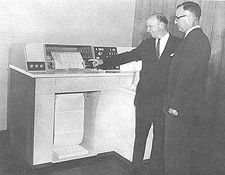 Photo by UNIVAC
Processor is asynchronous; system is asynchronous
Operation
Processor is sequential; however, step sequence may be
modified by plugboard wiring.
System is concurrent to the following degree:
Card Punch and Processor may operate simultaneously.
Card Reader, Printers and Punch may operate simultaneously.
STORAGE
No. of No. of Access
Medium Words Alphanum Char Microsec
Magnetic Core Variable 961 8
The system is not word oriented.
INPUT
80-Column Data Processor
Medium Speed
Punch Card Reader 300 - 400 cards/min
Read speed depends on number of columns read and amount
of processing time required per card.
For example, assume a maximum of 35 millisec of process time
required per card read. Also, all 80 columns are being read.
Under these conditions, a 300 card/min rate may be
maintained.
When only 40 columns are being ready and up to a maximum
of 35 millisec of process time is necessary, a rate of 400
cards/min may be maintained.
90-Column Data Processor
Medium Speed
Punch Card Reader 300 - 400 cards/min
Read speed depends on the number of frames and amount of
processing necessary per card. (A frame is made up of an
upper column and the corresponding lower column of a 90
column card).
When reading 45 frames (90-columns) and using up to 35
millisec of process time, a card feeding speed of 300
cards/min may be maintained.
In the above example if the frames are reduced to 23 (46
columns), a card feeding speed of 400 cards min can be
maintained.
OUTPUT
80-Column Data Processor
Medium Speed
Printer (Alphanum Data) 300 lines/min
Printer (Numeric Data) 400 lines/min
Punch (Model No. 2009-00) Up to 200 cards/min
(Optional)
    Photo by UNIVAC

    Processor is asynchronous; system is asynchronous
   Operation
    Processor is sequential; however, step sequence may be
    modified by plugboard wiring.

    System is concurrent to the following degree:
    Card Punch and Processor may operate simultaneously.
    Card Reader, Printers and Punch may operate simultaneously.

      STORAGE
                     No. of       No. of            Access
     Medium          Words        Alphanum Char     Microsec
    Magnetic Core    Variable        961             8
     The system is not word oriented.

                 INPUT
      80-Column Data Processor
      Medium           Speed
    Punch Card Reader  300 - 400 cards/min

    Read speed depends on number of columns read and amount
    of processing time required per card.

    For example, assume a maximum of 35 millisec of process time
    required per card read. Also, all 80 columns are being read.
    Under these conditions, a 300 card/min rate may be
    maintained.

    When only 40 columns are being ready and up to a maximum
    of 35 millisec of process time is necessary, a rate of 400
    cards/min may be maintained.

      90-Column Data Processor
      Medium                Speed
    Punch Card Reader      300 - 400 cards/min

    Read speed depends on the number of frames and amount of
    processing necessary per card. (A frame is made up of an
    upper column and the corresponding lower column of a 90
    column card).

    When reading 45 frames (90-columns) and using up to 35
    millisec of process time, a card feeding speed of 300
    cards/min may be maintained.

    In the above example if the frames are reduced to 23 (46
    columns), a card feeding speed of 400 cards min can be
    maintained.

      OUTPUT

      80-Column Data Processor
      Medium                        Speed
    Printer (Alphanum Data)                 300 lines/min
    Printer (Numeric Data)                  400 lines/min
    Punch (Model No. 2009-00)               Up to 200 cards/min
     (Optional)
| BRL 1964, UNIVAC 1004 80/90, starting page 0275
|
    OUTPUT

      90-Column Data Processor
      Medium                     Speed
    Printer (Alphanum Data)     300 lines/min
    Printer (Numeric Data)      400 lines/min
    Punch (Model No. 2011-00)   Up to 200 cards/min
     (Optional)

    The print drum of the printer rotates at a constant speed of 400 rev/min
    or 150 millisec/rev. During each revolution of the print drum, one of
    the 63 different characters passes the printing position every 2.38
    millisec.

    Each character actually appears on the print drum in two horizontal
    rows, known as the ODD and EVEN Rows. The characters which print in the
    odd printing positions are located in the odd rows, while the characters
    which print in the even printing positions are located in the even rows
    in the following manner:

      Odd "A" Row A A A A    Prints in ODD  position
     Even "A" Row  A A A A   Prints in EVEN position
      Odd "B" Row B B B B    Prints in ODD  position
     Even "B" Row  B B B B   Prints in EVEN position

    Each odd or even row time is one half the 2.38 millisec character time,
    or 1.19 millisec.

    The fact that the characters are arranged in odd and even rows has no
    special significance in computing printing speeds.

    When printing is initiated by a Print-Execute instruction, the processor
    is interlocked until all characters in print storage have been printed
    and cleared. As the rotation of the print drum causes a given character
    to move into printing position, print storage is scanned for the
    presence of that character. If a coincidence between the drum character
    in position to be printed and any of the characters stored in memory is
    detected, the characters in memory are printed and their print storage
    locations are cleared to spaces. After all the data in print storage has
    been printed and cleared, an interval of 1.19 millisec is required to
    detect that print storage is in a cleared condition and to release the
    processor interlock.

    Therefore, print-interlock time in milleseconds, i.e., the time required
    to complete a printing operation, is equal to 2.38N + 1.19 where N is
    equal to the number of characters that must pass the print position to
    completely print a line.

    It is to be noted that it is the number of characters that must pass the
    print position, not the number of characters that are to be printed,
    that determines the print time. The number of characters that must pass
    the print position for printing any given line, is determined by the
    location of those characters on the drum. To print all of the numerals
    (0 - 9) requires that ten characters pass the printing position. To
    print the two characters ampers and (&) and 4, requires that the print
    drum makes one-half revolution, which is equivalent to 32 character
    times, since these two characters are located opposite each other on the
    drum. The respective print time using the formula 2.38N + 1.19; for each
    of these examples is as follows:

    Print 0 - 9: 10 char x 2.38 millisec + 1.19 millisec = 24.99 millisec

    Print &, 4: 32 char x 2.38 millisec + 1.19 millisec = 78.35 millisec

    Because the print dawn is asynchronous with the processor, the position
    of the print drum will not be known when the first Print Execute is
    given. Therefore, the print interlock time, when printing the first
    line, may exceed the computed interlock time. For example, it has been
    previously established that ten character times are required to print
    the numerals

    0 - 9. However, during the printing of the first line, the Print-Execute
    instruction might be initiated when the numeral 9 is in position to be
    printed. After the 9 has been printed, the print drum must make
    virtually a complete revolution to complete the printing of the
    remaining numerals, 0 - 8. After the first line has been printed the
    print section will become synchronous with the processor program.

    A printing rate of 400 lines/min can be obtained if the sum of the print
    time, computed as described above, and the greater of the two overlapped
    compute and form spacing times does not exceed 150 millisec.

    CHECKING FEATURES

    Card Reader - Light-dark test for checking photocells.

    Card Punch - Weighted hole count used to verify accuracy of punching.

    80-Column Data Processor

    A Double-Punch - Blank column feature has been provided as an optional
    input check.

    90-Column Data Processor

    A Double-Punch - Blank column feature has been provided as an optional
    input check. This optional feature is intended primarily for use with
    the 80column 1004 but can be utilized with a 90 column 1004 for certain
    applications

    POWER, SPACE, WEIGHT, AND SITE PREPARATION

    Power, computer                    3.0  KVA
    Volume, computer                   135  cu ft
    Area, computer                    30.2  sq ft
    Area, working                      195  sq ft
        (Processor incl reader and printer)
    Room size                         15 x  14 ft (Approx minimum)
    Floor loading             62 lbs/sq ft
                             238 lbs/supporting jack pad
    Weight, computer       2,500 lbs

    (Includes card reader and printer)

    Air cooling is not required if intake air does not exceed 90oF. or relative
    humidity does not exceed 850. Air circulation requirement for the processor is
    250 cubic feet/min; for the punch, 600 cubic feet/min.

    COST, PRICE AND RENTAL RATES

    UNIVAC 1004 PRICE LIST
                              MONTHLY  PURCHASE
      MODEL                                 DESCRIPTION    RENTAL    PRICE
    1004-01 (Cd Processor) 90-Col                $1,150    $46,000
    1004-02 (Cd Processor) 80-Col                1,150     46,000
           Maximum Capacities
            31 Program Steps                80 Distributors
            30 Selectors                    45 Address Combines
            10 Program Selects               6 Comparators
            40 Collectors
    1004-03 (Cd Processor) 90-Col                1,400     56,000
    1004-04 (Cd Processor) 80-Col                1,400     56,000
           Maximum Capacities
            47 Program Steps                120 Distributors
            45 Selectors                     63 Address Combines
            15 Program Selects                8 Comparators
            65 Collectors
    1004-05 (Cd Processor) 90-Col                1,500     60,000
    1004-06 (Cd Processor) 80-Col                1,500     60,000
           Maximum Capacities
            62 Program Steps                160 Distributors
            60 Selectors                     80 Address Combines
            20 Program Selects               10 Comparators
           105 Collectors
| BRL 1964, UNIVAC 1004 80/90, starting page 0276
|
    MONTHLY PURCHASE

    MODEL                       DESCRIPTION RENTAL    PRICE
    1001+-07                    (Cd Processor)   $1 650.   $66 000
         Equipped to read 80 or
          90-Col. Code
         Maximum Capacities:

          62 Program Steps 160 Distributors
          60 Selectors    80 Address Combines
          20 Program Selects    10 Comparators
         105 Collectors
    2009-00 (ca Punch) 80-col               300       12,000
    2011-11 (ca Punch) 90-Col               300       12,.000

    OPTIONAL FEATURES & DEVICES FOR CARD PROCESSOR

    801  Short Cd Feeding Feature $         40   $ 1,600

         Permits feeding:
          1: 51 Col. Cds, 80-Co1.Code
          2: 29 Co. (29U/29L) Cds,
            90-Col. Code

    Code Image Read Feature 25  1,000
    Code Image Read & Punch 50  2,000

    PERSONNEL REQUIREMENTS

    One operator for each 8-hour shift.

    Training is made available by the manufacturer to the user includes up to
    70 hours of classroom training.

   ADDITIONAL FEATURES AND REMARKS

    Low operating cost, compact design, hip arithmetic speeds, card reading
    rate (400 cards/min), numeric print speed (400 lines/min), simplicity of
    programming, optional punch - punching speed 200 cards/min., and code
    image feature (90 Col. Data Processor). Unique system advantages include:

    Ability to accomplish calculating, decision making, tabulating, punching,
    and printing on the same card pass.

    Size of arithmetic results not restricted by size of registers.

    Data transfer and output editing accomplished on the same program step.

    Printer characteristics: sixty-three printable characters are standard. One
    hundred and thirty two characters may be printed on a single line.

    Speed of punch makes it usable as an output punch, not just a summary.
| BRL 1964, UNIVAC 1004 80/90, starting page 0277
|
| BRL 1964, UNIVAC 1020, starting page 0278
|
    UNIVAC 1020

    MANUFACTURER

    UNIVAC, Division of Sperry Rand Corp., St Paul, Minn.

    APPLICATIONS

    Missile Inertial Guidance (checkout, targeting, and calibration,
    using explicit, implicit, delta minimum, path adaptive, etc methods).
    Navigation (missile and aircraft) Spacecraft (manned and unmanned)
    Command & Control Process Control (Real Time) Fire Control Mobile
    Unit Command & Control (helicopter, orbital, hydrafoil, missile,
    aircraft). Data Processing (ASW, ECM, telemetry, data link) Flight
    Control & Adaptive Flight Control

                          PROGRAMMING AND NUMERICAL SYSTEM

    Internal number system      Binary
    Binary digits/word          24
    Binary digits/instruction   24
    Instructions/word            1
    Instructions decoded      1024
    Arithmetic system           Fixed point (fractional)
    Instruction type            One address
     Limited selectable other operand
    Number range       + 1 to - 1

    Instruction word format
    +-------+---------+-----------+---------+---------+
    | 0   1 | 2    3  | 4      7  | 8    10 | 11   23 |
    +-------+---------+-----------+---------+---------+
    | 3 B   | Acquire | Operation | Restore | Operand |
    | Boxes | A, U, X |           | or Test | Address |
    |       |         |           |         | 0-8191  |
    +-------+---------+-----------+---------+---------+


    Automatic built-in subroutines
     Increment ± 8
     Square-root
     External jump request
     Real-time interrupt
    Automatic coding.

     CS-1 Assembler operates on 1206 or USQ-20 computer,
    1206 and USQ-20 to ADD-1000 Code Converter, in-
    struction simulator, open loop guidance simulator.

    Registers and B-Boxes
      Instruction Register Z
      Arithmetic Registers M & M*
      Address Registers S & P
      3 Variable memory location usable as B-Box;
    variable memory locations used as A, X, and Interation Counter.
    Use of phase field logic sequence make 512 in, struction
    (4,096 B-boxed) with only 30 operation codes.

      ARITHMETIC UNIT

             Incl. Stor. Access Excl. Stor. Access
             Microsec      Microsec
    Add          6             3
    Mult     150 - 186
    Div         225
    Arithmetic mode     Parallel
    Timing              Synchronous
    Operation           Sequential

    STORAGE

                           No. of       No. of    Access
    Medium                 Words        Digits    Microsec

    Thin Film (Program)    4,096 -        24          3
                           7,168
    Thin Film (Variable)     256 -        24          3
                             512

    The program storage is of the non-destructive readout type of thin
    film storage. The variable (data) storage is of the destructive type.
    Magnetic tape

    No. of units that can be connected      16 Units

    Features of the tape unit depend on whether it is an airborne or
    ground system.

    INPUT
    Medium                          Speed     Remarks
    Accelerometer            300 microsec     Incremental
    Angle Optisyn           Program control   Gray Code
    Doppler Radar           Program control   24-bit Parallel
                                               data
    Paper Tape              Program control    6-bit Parallel

    Discrete Control        Program control   24-bit Parallel
    Real Time              5 & 50 millisec  1,000 cycles/sec

    OUTPUT
       Medium                       Speed   Remarks
    Dig. to Analog Conv         12 micro sec   Analog
    Relay Pullers            1,000 microsec Discrete 12-bit
      (1/2 amp )
    Punch & GSE               12 microsec   6-bit
    Punch & GSE               12 microsec   24-bit

     CHECKING FEATURES

    Fixed checking features include separately enabled special constant
    NDRO (non-destructive read out) and program NDRO memory sections, and
    arithmetic overflow indication and test. An optical check is an
    inhibit instruction execution from special constant regions.

    POWER, SPACE, WEIGHT, AND SITE PREPARATION
    Power, computer        0.202 Kw  0.202 KVA 1.0 pf
    Volume, computer       1.2 cu ft
    Area, computer         1.6 sq ft
    Weight, computer      62.0 lbs
      A DC to DC converter is used.

    Only room air conditioning as otherwise required is necessary.

    RELIABILITY, OPERATING EXPERIENCE

    The mean time between failures (MTBF) is 10,000 hours.

    ADDITIONAL FEATURES AND REMARKS
    Outstanding features include the use of silicon semiconductors,
    encapsulated welded--cordwood construction, magnetic thin-film,
    random access,
| BRL 1964, UNIVAC 1020, starting page 0279
|
electrically alterable NDRO and DRO memory, self contained power
supply and self contained input output.
Other advantages are on-line self-loading of program and constants
while computer is mounted in carrier vehicle; programmable output
on telemetry serializer; timed interrupt and priority control
circuits, completely random access memory with full subroutine and
indexing capabilities.
The computer includes analog to digit and digital to analog
converters, gyro torquing signals, incremental inputs, PCM
telemetry serializer and formatter, and other missile system and
ground system interface matching within its weight and volume. The
computer has two types of interrupts one an incremental input which
changes the content of any variable memory cell by + 8 on external
request and another which transfers program control (fixed
subroutine jumps) on external request. The computer also includes a
real-time clock input for synchronization and program segmentation.
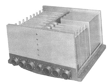 Photo by UNIVAC Division
| BRL 1964, UNIVAC 1050, starting page 0280
|
UNIVAC 1050
MANUFACTURER
UNIVAC Division, Sperry Rand Corp.
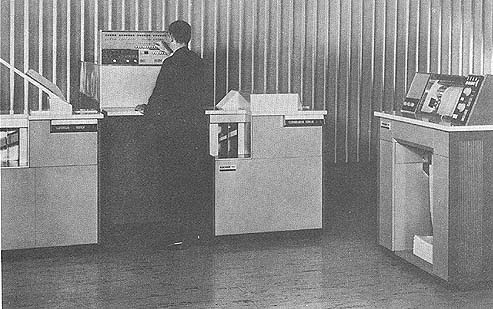 Photo by UNIVAC Division, Sperry Rand Corp.
APPLICATIONS
A general purpose subsystem employed mainly to
supplement the parallel processing capabilities of UNIVAC
III, UNIVAC 490 Real-Time and UNIVAC 1107 Thin Film
Memory Computing systems.
PROGRAMMING AND NUMERICAL SYSTEM
Internal number system Binary coded decimal
There are six bits plus one parity bit per character
Decimal digits/word Variable
Digits/instruction 30
Instructions/word Not word oriented
Instructions decoded 43
Arithmetic system Fixed point
Instruction type One address
Number range From +9999999999999999 to
- 9999999999999999
Instruction word format
+-----------+-----------+------------+-----------+-----------+
| lst | 2nd | 3rd | 4th | 5th |
| CHARACTER | CHARACTER | CHARACTRER | CHARACTER | CHARACTER |
+---------+-+-----+----++------------+-----------+-----------+
| 30 26 | 25 23 | 22 | 21 7 | 6 1 |
| a | b | c | d | e |
+---------+-------+----+-------------------------+-----------+
a. Operation Code d. Main Store Address
b. Index Register e. Detail Field
c.Reserved
The first five bits of the instruction, bits 30 through 26, are
the operation code. The operation code specifies the
function which the Central Processor is to execute.
Bits 25 through 23 are the index register (X) portion of the
instruction. The concept of indexing is discussed below
under "Registers and B-Boxes".
Bit 22 is reserved. It must always be zero.
Bits 21 through 7 are the main store address (M) portion of
the instruction. This portion specifies the store address of
the operand. If an operand is
Photo by UNIVAC Division, Sperry Rand Corp.
APPLICATIONS
A general purpose subsystem employed mainly to
supplement the parallel processing capabilities of UNIVAC
III, UNIVAC 490 Real-Time and UNIVAC 1107 Thin Film
Memory Computing systems.
PROGRAMMING AND NUMERICAL SYSTEM
Internal number system Binary coded decimal
There are six bits plus one parity bit per character
Decimal digits/word Variable
Digits/instruction 30
Instructions/word Not word oriented
Instructions decoded 43
Arithmetic system Fixed point
Instruction type One address
Number range From +9999999999999999 to
- 9999999999999999
Instruction word format
+-----------+-----------+------------+-----------+-----------+
| lst | 2nd | 3rd | 4th | 5th |
| CHARACTER | CHARACTER | CHARACTRER | CHARACTER | CHARACTER |
+---------+-+-----+----++------------+-----------+-----------+
| 30 26 | 25 23 | 22 | 21 7 | 6 1 |
| a | b | c | d | e |
+---------+-------+----+-------------------------+-----------+
a. Operation Code d. Main Store Address
b. Index Register e. Detail Field
c.Reserved
The first five bits of the instruction, bits 30 through 26, are
the operation code. The operation code specifies the
function which the Central Processor is to execute.
Bits 25 through 23 are the index register (X) portion of the
instruction. The concept of indexing is discussed below
under "Registers and B-Boxes".
Bit 22 is reserved. It must always be zero.
Bits 21 through 7 are the main store address (M) portion of
the instruction. This portion specifies the store address of
the operand. If an operand is
| BRL 1964, UNIVAC 1050, starting page 0281
|
    greater than one character in length, the M portion refers to the
    least significant character of the operand. There are two exceptions
    to this rule: The Zero Suppress and the Block Transfer instructions.
    Because of the way these two instructions operate, the M portion
    specifies the most significant character of the operand.

    Bits 6 through 1 comprise the detail field. The contents of the
    detail field vary with each instruction. Depending on the
    instruction, the detail field may specify operand length, tetrad
    number, a comparison indicator, an arithmetic register, or number of
    bits. The function of the detail field is discussed thoroughly in the
    description of the UNIVAC 1050 instruction repertoire.

    Automatic coding.

    PAL Assembly System, Co-ordination Routine and Relocatable Relative
    Loader, Source Code Library, Input/Output Library, Patch Assembler

    Registers and B-Boxes

    Two arithmetic registers of 16 characters each

    Seven index registers. An index register contains 15 bits. The
    primary function of an index register is to vary the operand address
    specified in an instruction. If an index register is specified in an
    instruction, the effective address of the instruction is determined
    by adding the contents of the specified index register to the address
    specified by the M portion of the instruction. However, neither the
    contents of the index register nor the M portion are changed, except
    in some cases of the Fix Tetrad instruction. Location and length of
    operands are specified by each instruction. The first 256 characters
    of storage are grouped into 64 four-character fields (tetrads) and
    can be so addressed.

    To illustrate indexing, assume an instruction which stores a value in
    location 100. Assume that the instruction specifies indexing by index
    register 1, which contains the value 20. When the instruction is
    executed, the value being stored is placed in 100+20, or 120. After
    the instruction has been executed, the M portion of the instruction
    still specifies location 100, and'index register 1 still contains 20.

    The value of indexing is that one set of instructions may be made to
    process several similar items of data located in different areas of
    main store. Instead of writing as many sets of processing
    instructions as there are items of data in store, the programmer need
    write only one set of instructions using index register modification.
    In order to perform the same processing on several items of data
    located in different parts of store, all that is necessary is to
    change the value of the index register.

    Almost all instructions may specify index register modification. If
    indexing is not required in an instruction, the index register
    portion of the instruction must contain binary zeroes.

      ARITHMETIC UNIT
           Incl. Stor. Access           Excl. Stor. Access
           Microsec                     Microsec
    Add     270 (a+b=c) 5-digit sum         117 (5 digit sum)
    Mult    567 (axb=c) 6-digit prod.       229 (6 digit prod)
    Div   1,735 (a/b=c) 5-digit quotient  1,438(5 digit quotient)
    Arithmetic mode       Serial

    This system is parallel by bit and serial by
    character.
    Timing             Synchronous
    Operation          Concurrent

    STORAGE
                No. of             Access
      Medium    Alphan Char.       Microsec
    Core        8,192 - 32,768      4.5/Char

    Regarding core memory, basic system includes 8,192 character or digit
    positions of storage which may be expended to 32,768 in increments of
    4,096 positions.

    The UNIVAC 1050 Central Processor has from 2 to 8 modules of main
    store, each module comprising 4,096 positions or locations. Each
    position has its own unique address, and each position is directly
    addressable.

    Each location contains six information bits and one parity bit. The
    parity bit is of no concern to the programmer, as it is used only by
    the hardware.

    Program instructions and data are contained in main store. Each
    instruction occupies five consecutive locations. Instructions are
    always represented internally in binary form.

    Magnetic tape

    2 Model IIIA units or 2 Model IIIC units may be connected. (See chart
    for additional information).

       INPUT

    Medium                          Speed
    Uniservo IIIA
    Uniservo IIIC
    Punched Card Reader      1,000 cards/min
     One card reader per system.

       OUTPUT

    Medium                          Speed
    Uniservo IIIA
    Uniservo IIIC
    Card Punch Unit         300 cards/min
     One card punch per system.
    Printer                 700-922 lines/min

    Single spaced alphanumeric data printer, 128 characters/line; one
    printer/system.

    The system may include two IIIA Tape Units or two IIIC Tape Units.
    Combinations of IIIA and IIIC Tape Units are not permitted.

    The printer prints 700 lines/min using all 63 characters on the print
    drum.

    The printer prints 922 lines/min using 40 contiguous characters on
    the print drum.

    CHECKING FEATURES

    Tape Units - Read after Write check is included.

    Fixed -Card Reader - Solar cells sensing units are checked before
    each card is read.

    Fixed -Card Punch - Post-Punch check read station enables positive
    hole count check of data that was previously punched.

    Fixed Parity checking is also employed throughout the system as well
    as decimal overflow, and check for improper division.

    REMARKS

    The UNIVAC 1050 Data Processing System consists of three physical
    categories: Central Processor modules, input/output equipment, and
    magnetic tape handling equipment.

    The Central Processor unit is composed of two modules placed side by
    side to form one composite unit. These modules are the Central
    Processor Unit and the Central Processor Power Supply Unit.
| BRL 1964, UNIVAC 1050, starting page 0282
|
 The input/output equipment consists of the following
physically separated units: High-Speed Reader High-Speed
Printer Card-Punch Unit
The magnetic tape equipment consists of the following
modules: UNISERVO Synchronizer UNISERVO Power
Supply Unit UNISERVO IIIA or UNISERVO IIIC Tape
Handling Units
The customer is responsible for the installation of the AC
power distribution system to the point of connection to the
UNIVAC 1050 units. A 25% safety factor must be added to
the total power requirements to provide for the utilization of
convenience receptacles located on the individual units.
The composite unit composed of the Central Processor Unit
and the Central Processor Power Supply Unit requires a
208-Volt, 1-Phase, 60-Cycle, 3-Wire (plus a separate
grounding conductor) cable. Power connects to the Central
Processor Power Supply Unit. The Central Processor Unit
receives power from the Central Processor Power Supply
Unit.
The High-Speed Reader, High-Speed Printer and Card
Punch Unit receive power from the Central Processor
Power Supply.
The magnetic tape equipment requires a 208-Volt, 1-Phase,
60-Cycle, 3-Wire (plus a separate grounding conductor)
cable. Power connects to the UNISERVO Power Supply
Unit.
PERSONNEL REQUIREMENTS
One 8-Hour Shift
Supervisors 2
Analysts 1
Programmers 3
Librarians 1
Operators 1
In-Output Oper 1
Training will be made available to all users.
ADDITIONAL FEATURES AND REMARKS
Printer has a buffer. Card Reader, Punch, Printer and Tape
Control Unit have separate input/output channels.
Automatic interrupt feature makes it possible to
simultaneously process multiple applications. Simultaneous
operations are: read cards, punch, process and print; read
tape, process and print; write tape, process and print.
UNIVAC 1050 is a solid state, character addressable
computing sub-system. It has a basic magnetic core memory
of 8,192 six-bit alphanumeric characters that can be
expanded in modules of 4,096 characters to a maximum
capacity of 32,768. The 1050 was designed to supplement
the parallel processing capabilities of the UNIVAC III, 490
Real Time, and 1107 Thin Film Memory computing
systems.
    The input/output equipment consists of the following
    physically separated units: High-Speed Reader High-Speed
    Printer Card-Punch Unit

    The magnetic tape equipment consists of the following
    modules: UNISERVO Synchronizer UNISERVO Power
    Supply Unit UNISERVO IIIA or UNISERVO IIIC Tape
    Handling Units

    The customer is responsible for the installation of the AC
    power distribution system to the point of connection to the
    UNIVAC 1050 units. A 25% safety factor must be added to
    the total power requirements to provide for the utilization of
    convenience receptacles located on the individual units.

    The composite unit composed of the Central Processor Unit
    and the Central Processor Power Supply Unit requires a
    208-Volt, 1-Phase, 60-Cycle, 3-Wire (plus a separate
    grounding conductor) cable. Power connects to the Central
    Processor Power Supply Unit. The Central Processor Unit
    receives power from the Central Processor Power Supply
    Unit.

    The High-Speed Reader, High-Speed Printer and Card
    Punch Unit receive power from the Central Processor
    Power Supply.

    The magnetic tape equipment requires a 208-Volt, 1-Phase,
    60-Cycle, 3-Wire (plus a separate grounding conductor)
    cable. Power connects to the UNISERVO Power Supply
    Unit.

    PERSONNEL REQUIREMENTS

    One 8-Hour Shift

    Supervisors                        2
    Analysts                           1
    Programmers                        3
    Librarians                         1
    Operators                          1
    In-Output Oper                     1

    Training will be made available to all users.

      ADDITIONAL FEATURES AND REMARKS

    Printer has a buffer. Card Reader, Punch, Printer and Tape
    Control Unit have separate input/output channels.
    Automatic interrupt feature makes it possible to
    simultaneously process multiple applications. Simultaneous
    operations are: read cards, punch, process and print; read
    tape, process and print; write tape, process and print.

    UNIVAC 1050 is a solid state, character addressable
    computing sub-system. It has a basic magnetic core memory
    of 8,192 six-bit alphanumeric characters that can be
    expanded in modules of 4,096 characters to a maximum
    capacity of 32,768. The 1050 was designed to supplement
    the parallel processing capabilities of the UNIVAC III, 490
    Real Time, and 1107 Thin Film Memory computing
    systems.
| BRL 1964, UNIVAC 1050, starting page 0283
|
 Auxiliary off line functions include conversion of
data from punched cards to magnetic tape and from
magnetic tape to punched cards or printed hard copy.
A program interrupt technique allows the concurrent
operation of two input/output programs. Modular
construction of the 1050 system permits the user to
select only those components needed to fill his
requirements. Rental price ranges from $5,700 to
$10,850 per month depending on configuration.
Purchase prices range from approximately $285,000
to approximately $500,000. Delivery is one year from
receipt of order.
      Auxiliary off line functions include conversion of
     data from punched cards to magnetic tape and from
     magnetic tape to punched cards or printed hard copy.
      A program interrupt technique allows the concurrent
     operation of two input/output programs. Modular
     construction of the 1050 system permits the user to

    select only those components needed to fill his
    requirements. Rental price ranges from $5,700 to
    $10,850 per month depending on configuration.
    Purchase prices range from approximately $285,000
    to approximately $500,000. Delivery is one year from
    receipt of order.
| BRL 1964, UNIVAC 1206, starting page 0284
|
UNIVAC 1206
Military Computer
MANUFACTURER
UNIVAC, Division of Sperry Rand Corp.
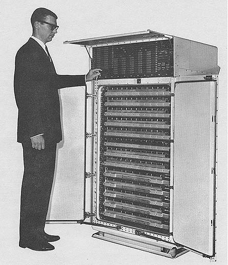 Photo by UNIVAC Div of Sperry Rand Corp.
APPLICATIONS
General purpose computing Real-time tactical analysis, display
and weapons control. Missile tracking Range instrumentation
Missile guidance Missile fire control Simulation Logistics
Tactical control
Digital communications
Data reduction and analysis
Inventory and scheduling
PROGRAMMING AND NUMERICAL SYSTEM
Internal number system Binary
Binary digits/word 30
Binary digits/instruction 30
Instructions/word 1
Photo by UNIVAC Div of Sperry Rand Corp.
APPLICATIONS
General purpose computing Real-time tactical analysis, display
and weapons control. Missile tracking Range instrumentation
Missile guidance Missile fire control Simulation Logistics
Tactical control
Digital communications
Data reduction and analysis
Inventory and scheduling
PROGRAMMING AND NUMERICAL SYSTEM
Internal number system Binary
Binary digits/word 30
Binary digits/instruction 30
Instructions/word 1
| BRL 1964, UNIVAC 1206, starting page 0285
|
    Instructions decoded               62

     Most instructions have conditional program branches.
    Arithmetic system                  Fixed point
    Parallel one's complement, subtractive arithmetic is used.
    Instruction type                   One address

    Number range ± 536,870,971 (29 bits + sign)
    Instruction word format

    The j designator allows arithmetic instructions to perform decision
    making, with an optional skip programmed to occur when certain
    conditions of the A or 0 register are encountered. Illegal divide
    attempts and parity count may also be programmed with the j designator.

    A repeat instruction exists, as well as logical instructions for
    accessibility to individual bits.

    Three separate interrupt locations exist for each I/0 channel, each
    showing different conditions. In addition, there is a fault interrupt if
    an illegal instruction is attempted.

    Automatic built-in subroutines include automatic recovery and bootstrap
    routines.

    Automatic coding includes the CS-1 compiler, a binary data processing
    problem-oriented language.

    Registers and B-Boxes
    7 B-Boxes (Index registers)
    1 A Register (Accumulator)
    1 Q Register (for double length words - may be used as another
    accumulator)

    ARITHMETIC UNIT
             Incl. Stor. Access     Excl. Stor. Access
             Microsec               Microsec
    Add            16                9.6
    Mult           35.2 - 112       35.2 - 112
    Div           112              112

    Arithmetic mode    Parallel
    Timing             Synchronous
    Operation          Sequential/Parallel

    STORAGE

                      No. of      No. of        Access
                      Words       Digits        Microsec
    Magnetic core       32,768     30               3.6
    Wired                                           8.0 (cycle)
    Wired plugboard         16     30               3.6
    FH-880 Drum, Non-  786,432     30          17,000 (average)
     militarizedwords/drum
    8 drums are possible per computer channel
    360,000 chars/sec transfer rate

    Magnetic tape                          (1)          (2)
     No.of chars/linear inch           200,128      125,250 Char/inch
    Channels am tracks on the tape           8            8 Track/Tape
    Blank tape separating each record        1.5          1.05 Inches
    Tape speed                             112.5        100 Inches/sec
    Transfer rate             36,000;   20,000    12,500;
                                                      2,500 Char/sec
    Start time                               8           12   Millisec
    Stop time                                6            9 Millisec
     Average time for experienced
    operator to change reel of tape         60           30 Seconds
     Physical properties of tape
      Width                                  0.5          0.5 Inches
      Length of reel                     2,400        2,400 Feet
      Composition                          Mylar      Metal or Mylar,

    System 1 consists of 2 tape units per computer channel in one
    militarized cabinet. Two modes of recording and reading are possible
    under program control, one with redundant recording (3 information
    bits/char), one with odd parity generated and checked (6 information
    bits/ characters).

    System 2 is the standard commercial Uniservo IIA available on the UNIVAC
    490 and other UNIVAC products. Up to 12 may be attached to each channel
    of the computer.

    INPUT
          Medium               Speed

    Card Reader            600 cards/min (Commercial, 80 or 90 cot)
    Paper Tape             200 chars/sec (5 to 8 level)
    Flexowriter or
     Teletype               10 chars/sec
    Videoprocessors           (For radar data conver.)
    Communications Control Equipment
    Keyset Central - Multiplexer for manual entry devices

    OUTPUT
        Medium               Speed

    High Speed Printer      600 lines/min (Commercial 128 char/line)
    Card Punch              150 cards/min (Commercial 80 or 90 col.)
    Paper Tape               60 chars/sec (5 to 8 level)
    Flexowriter or
     Teletype                10 chars/sec
    Communication Control Equipment

    Operating console is above the door. A separate desktype operating
    console is available as optional equipment.

    CIRCUIT ELEMENTS OF ENTIRE SYSTEM
    Type                          Quantity
    Tubes                                0
    Diodes                          37,298
    Transistors                     10,702
    Resistors                       43,202
    Capacitors                       2,766
    Magnetic Cores          983,040 (32,768 words)

        CHECKING FEATURES

    Programmed parity check exists for the central computer.

      POWER, SPACE, WEIGHT, AND SITE PREPARATION

    Power, computer                         2.5 Kw    3.1 KVA   0.8 pf
    Power, blower                           2.0 Kw    2.2 KVA   0.9 pf
    Volume, computer                        58.6 cu ft
    Area, computer                          9.8 sq ft
    Floor loading                           237 lbs/sq ft
                                            237 concen max
    Weight, computer                        2,320 lbs

    Ambient air cooled or water cooled equipment are included in the
    computer cabinet.
The j designator allows arithmetic instructions to perform decision
making, with an optional skip programmed to occur when certain
conditions of the A or 0 register are encountered. Illegal divide
attempts and parity count may also be programmed with the j designator.
A repeat instruction exists, as well as logical instructions for
accessibility to individual bits.
Three separate interrupt locations exist for each I/0 channel, each
showing different conditions. In addition, there is a fault interrupt if
an illegal instruction is attempted.
Automatic built-in subroutines include automatic recovery and bootstrap
routines.
Automatic coding includes the CS-1 compiler, a binary data processing
problem-oriented language.
Registers and B-Boxes
7 B-Boxes (Index registers)
1 A Register (Accumulator)
1 Q Register (for double length words - may be used as another
accumulator)
ARITHMETIC UNIT
Incl. Stor. Access Excl. Stor. Access
Microsec Microsec
Add 16 9.6
Mult 35.2 - 112 35.2 - 112
Div 112 112
Arithmetic mode Parallel
Timing Synchronous
Operation Sequential/Parallel
STORAGE
No. of No. of Access
Words Digits Microsec
Magnetic core 32,768 30 3.6
Wired 8.0 (cycle)
Wired plugboard 16 30 3.6
FH-880 Drum, Non- 786,432 30 17,000 (average)
militarizedwords/drum
8 drums are possible per computer channel
360,000 chars/sec transfer rate
Magnetic tape (1) (2)
No.of chars/linear inch 200,128 125,250 Char/inch
Channels am tracks on the tape 8 8 Track/Tape
Blank tape separating each record 1.5 1.05 Inches
Tape speed 112.5 100 Inches/sec
Transfer rate 36,000; 20,000 12,500;
2,500 Char/sec
Start time 8 12 Millisec
Stop time 6 9 Millisec
Average time for experienced
operator to change reel of tape 60 30 Seconds
Physical properties of tape
Width 0.5 0.5 Inches
Length of reel 2,400 2,400 Feet
Composition Mylar Metal or Mylar,
System 1 consists of 2 tape units per computer channel in one
militarized cabinet. Two modes of recording and reading are possible
under program control, one with redundant recording (3 information
bits/char), one with odd parity generated and checked (6 information
bits/ characters).
System 2 is the standard commercial Uniservo IIA available on the UNIVAC
490 and other UNIVAC products. Up to 12 may be attached to each channel
of the computer.
INPUT
Medium Speed
Card Reader 600 cards/min (Commercial, 80 or 90 cot)
Paper Tape 200 chars/sec (5 to 8 level)
Flexowriter or
Teletype 10 chars/sec
Videoprocessors (For radar data conver.)
Communications Control Equipment
Keyset Central - Multiplexer for manual entry devices
OUTPUT
Medium Speed
High Speed Printer 600 lines/min (Commercial 128 char/line)
Card Punch 150 cards/min (Commercial 80 or 90 col.)
Paper Tape 60 chars/sec (5 to 8 level)
Flexowriter or
Teletype 10 chars/sec
Communication Control Equipment
Operating console is above the door. A separate desktype operating
console is available as optional equipment.
CIRCUIT ELEMENTS OF ENTIRE SYSTEM
Type Quantity
Tubes 0
Diodes 37,298
Transistors 10,702
Resistors 43,202
Capacitors 2,766
Magnetic Cores 983,040 (32,768 words)
CHECKING FEATURES
Programmed parity check exists for the central computer.
POWER, SPACE, WEIGHT, AND SITE PREPARATION
Power, computer 2.5 Kw 3.1 KVA 0.8 pf
Power, blower 2.0 Kw 2.2 KVA 0.9 pf
Volume, computer 58.6 cu ft
Area, computer 9.8 sq ft
Floor loading 237 lbs/sq ft
237 concen max
Weight, computer 2,320 lbs
Ambient air cooled or water cooled equipment are included in the
computer cabinet.
| BRL 1964, UNIVAC 1206, starting page 0286
|
    Site preparation requirements.

    May be ship or van mounted. If water cooled, fresh water at
    70o (± 5o) and 6.3 gals/min is required.
    Power may be 440 volt, 3 phase 60 cycle; 208 volts, 3 phase, 400 or 60 cycle.

     COST, PRICE AND RENTAL RATES

                               Purchase
    1206 Computer, 32,000 memory            $ 363,000

       Militarized tape system (2 handlers)    80,500
       Monitoring typewriter                   46,000
       Paper tape system                        4,000
        Total                                 532,500

    Additional equipment
       Teletype w/teletype adapter (ANUGC-13)  24,000

    Maintenance & operators console (remote)   28,200

    Fixed price sale only on 1206 basic system.

    Monthly rental rates for additional equipment.

    Power supply                              $  7150
    Uniservo 11A                                  450
    Control & Synchronizer                      1,530
    High Speed Printer                            500
    Control & Synchronizer                      1,450
    Card Reader                                   350
    Card Punch                                    500

    Card Control & Synchronizer (will handle

    1 reader & 1 punch)                         1,600

    FH 880 Drum                                 2,000
    Control & Synchronizer                      1,420

    Maintenance/service contracting is available according
    to equipment purchased.

      PERSONNEL REQUIREMENTS

            One 8-Hour Two 8-Hour Three 8-Hour
                Shift  Shifts Shifts
    Supervisors   1       1      1
    Analysts      2       2      2
    Programmers   8      10     12
    Clerks        3       3      3
    Librarians    1       1      1
    Operators     3       5      7
    Engineers     1       2      2
    Technicians   1       2      3

    Training made available by manufacturer to users include
    courses in programming and maintenance, which are held
    upon request at St. Paul, Minnesota and San Diego,
    California.

    UNIVAC Field Service maintenance is available on a world
    wide basis.

      RELIABILITY, OPERATING EXPERIENCE

    The typical average mean-time-between-failures (MTBF) of
    over 1,000 hours is now being attained by computers in the
    field. This high figure is attained

    through complete analysis of every component that fails
    anywhere in the world. This information is transmitted to
    vendors for corrective action when necessary.

      ADDITIONAL FEATURES AND REMARKS

    Outstanding features include a real-time clock, buffered
    input/output, 14 I/0 channels 2 of which provide for direct
    communication with two other computers, automatic
    recovery, reliability of operation, powerful instruction
    repertoire, small size resistant to shock, vibration, unusual
    climatic conditions, the CS-1 compiler, which offers a
    language oriented to real-time data handling, and militarized
    peripheral/equipment capable of handling inquiry stations,
    displays, communication equipment, analog signals, and
    radar video signals.

    Repertoire of 62 Instructions with conditional program
    branching. Average execution time of 13 microseconds. CS-1
    automatic programming compiler for ease of programming.

    Internal 24-hour Real-Time Clock for accurately initiating or
    terminating operations at specified times.

    Up to 12 Input, 12 Output Channels with parallel mode of
    operation (60,000 transmissions per second per channel).

    2 Special Input, 2 Special Output Channels for direct
    communication between computers.

    Programmed Checking of Data Parity.

    Auxilary 16-Word Permanent Memory for bootstrap automatic
    recovery in the event of program failure.

    The UNIVAC 1206 Military Computer combines a range of
    abilities and applications never before available in one
    compact package. It is a stored program computer for rapid
    processing of large quantities of complex data.

    The 1206 can operate in mobile, rugged environments under
    adverse field conditions. It is specifically designed to
    communicate easily with a wide variety of asynchronous
    external devices in real-time applications. The system is
    built to MIL-E-16400 (initially for the Naval Tactical Data
    System - NTDS).

    FUTURE PLANS

    Increased speed capability is under development.
| BRL 1964, UNIVAC 1206, starting page 0287
|
| BRL 1964, UNIVAC 1212, starting page 0288
|
UNIVAC 1212
CP 642B Computer
MANUFACTURER
UNIVAC Division of Sperry Rand Corp. (Military
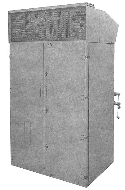 Photo by UNIVAC Div of Sperry Rand Corp.
APPLICATIONS
General Purpose Computation
Real Time Weapons Guidance Command and Control
Range Tracking Applications
Simulation
Range Instrumentation
Logistical Problems
Communications Network Data Handling
PROGRAMMING AND NUMERICAL SYSTEM
Internal number system Binary
Binary digits/word 30
Binary digits/instruction 30
Instructions/word 1
Instructions decoded 62 with modifiers and
branching
Arithmetic system Fixed point
One's complement subtractive arithmetic is used.
Instruction type One address
Number range ± 536,80,911 (29 bits + sign
+-----------------+--------+--------+-------+-------+-----------+
| | 29 24 | 23 21 | 20 18 | 17 15 | 14 0 |
| Data Processing +--------+--------+-------+-------+-----------+
| | f | j | k | b | y |
+-----------------+--------+--------+-------+-------+-----------+
f - function code
j - provides 1/2 word addressability
b - index register designation
y - operand
Photo by UNIVAC Div of Sperry Rand Corp.
APPLICATIONS
General Purpose Computation
Real Time Weapons Guidance Command and Control
Range Tracking Applications
Simulation
Range Instrumentation
Logistical Problems
Communications Network Data Handling
PROGRAMMING AND NUMERICAL SYSTEM
Internal number system Binary
Binary digits/word 30
Binary digits/instruction 30
Instructions/word 1
Instructions decoded 62 with modifiers and
branching
Arithmetic system Fixed point
One's complement subtractive arithmetic is used.
Instruction type One address
Number range ± 536,80,911 (29 bits + sign
+-----------------+--------+--------+-------+-------+-----------+
| | 29 24 | 23 21 | 20 18 | 17 15 | 14 0 |
| Data Processing +--------+--------+-------+-------+-----------+
| | f | j | k | b | y |
+-----------------+--------+--------+-------+-------+-----------+
f - function code
j - provides 1/2 word addressability
b - index register designation
y - operand
| BRL 1964, UNIVAC 1212, starting page 0289
|
    +-----------------+--------+--------+-------+-------+-----------+
    |                 | 29  24 | 23  20 | 19 18 | 17 15 | 14      0 |
    | Input/Output    +--------+--------+-------+-------+-----------+
    |                 |    f   |   j    |   k   |  b    |     y     |
    +-----------------+--------+--------+-------+-------+-----------+

    f - function code
    j - I/0 channel designation
    k - operand source designation for I/0
    b - index register designation
    y - operand

    Automatic built-in subroutines
    2 operator selectable wired bootstrap routines of 32 instructions.

    Automatic coding.
    CS-1 compiler; AS-1 assembler; problem oriented languages

    Registers and B-Boxes include 7 index registers
       located in the thin-film memory.

    A built in square root command has been made as a special condition of the
    divide. Command time to executed is 47 microseconds.

    The I/0 capabilities of this computer are increased by virtue of the fact that
    special I/0 control words are located in thin-film memory with an access time of
    only 2/3 microseconds. This allows transfer of 30-bit I/) data to and from
    computer memory in 2 memory cycles at a rate of 8 microseconds/word.

    ARITHMETIC UNIT

             Incl. Stor. Access    Excl. Stor. Access
             Microsec              Microsec
    Add        8                       4
    Mult    32 - 48                28 - 44
    Div       47                      43

    Arithmetic mode    Parallel
    Timing             Synchronous
    Operation          Sequential & Concurrent

    STORAGE

                       No. of        No. of    Access
    Medium             Words         Digits    Microsec

    Magnetic Core     32,662        30-bits      2 access
                                                 4 cycle
    Magnetic Thin Film    64        30-bits      0.67
    Wired Memory      Two 32        30-bits      2 access
                     word                        4 cycle
                   memories
    Magnetic tape
    No. of units that can be connected      16 Units
    No. of chars/linear inch               200/556 Chars/inch
    Channels or tracks on the tape           8 Track/tape
    Blank tape separating each record        0.75 Inches
    Tape speed                             112.5 Inches/sec
    Transfer rate                       22,500 to 62,500 Chars/sec
    Start time (Max)                         3 Millisec
    Stop time (max)                          3 Millisec
    Average time for experienced
    operator to change reel of tape         30   Seconds
     Physical properties of tape
      Width                                  0.5    Inches
      Length of reel                     2,400      Feet
      Composition                          Mylar

    Up to 16 tape handlers per I/0 channel. Each channe must have 1 synchronizer.
    The unit may be used in an "IBM compatible mode" with IBM 727, 729 III and
    729 IV tape systems. Rewind is at 225 inches/second.

    INPUT

         Medium                      Speed
    Card Reader       600 cards/min (80 or 90 column)
    Paper Tape     200 to 300 feet/sec (5-8 level)
    Flexowriter or                          10 chars/sec
       Teletype
    Various Video Display Processors
    Communications Control Equipment
    Keyset Central (A multiplexor with spec manual inputs)

    OUTPUT
         Medium                      Speed
    High Speed Printer         700-1,000 cards/min (Commercial
                                              120 char/line)
       250 LPM                 250 cards/min (Commercial
                                               72 char/line)
    Card Punch                 150 cards/min
    Paper Tape                 110 chars/sec (5-8 level)
    Flex & Teletype             10 chars/sec

    CIRCUIT ELEMENTS OF ENTIRE SYSTEM
         Type                     Quantity
    Tubes                                0
    Diodes                          35,000
    Transistors                      9,500
    Magnetic Cores                 979,860

   CHECKING FEATURES

    Checking features include programmed parity checks in central computer.

    POWER, SPACE, WEIGHT, AND SITE PREPARATION

    Power, computer              2.5 Kw 3.0 KVA   0.8 pf
    Power, air conditioner       2.0 Kw 2.2 KVA 0.9 pf
    Volume, computer            58.0 cu ft
    Area, computer               9.8 sq ft
    Floor loading               23.7 lbs/sq ft
                                23.7 lbs concen max
    Weight, computer         2,300 lbs

    Site preparation requirements

    May be ship or van mounted. If water cooled, fresh water at 70oF ±5o
    6.3 gal/minute required.

    Power may be 440 V 3 Phase 60 cycles/sec. 208 V 3 Phase 400 or
    60 cycles/sec (M-G Set inputs).

                            COST, PRICE AND RENTAL RATES

    Basic System/Component        Purchase

    CP-642B 132K core memory & 16 I/0 channels $400,000
    Type 1240 tape system/4 handlers                  115,000
    1000 CPM printer/sync.          68,000
    TTY and Adapter (AN/UGE-6)      24,000
    Computer Console                  est.  24,000

    Fixed price sale only CP-642B Unit

    Uniservo IIA's Card Reader and UNIVAC LPM: printers are available for rental.

    Maintenance on UNIVAC commercial peripherals can be supplied.

    PERSONNEL REQUIREMENTS

                     One 8-Hour Two 8-Hour Three 8-Hour
                     Shift      Shifts     Shifts
      Supervisors      1          1          1
      Analysts         2          2          2
      Programmers      8         10         12
      Clerks           3          3          3
| BRL 1964, UNIVAC 1212, starting page 0290
|
                     One 8-Hour  Two 8-Hour  Three 8-Hour
    (Cont'd)         Shift       Shifts       Shifts
    Librarians         1           1             1
    Operators          3           5             7
    Engineers          1           2             2

    Training in operation maintenance and programming can be furnished
    at UNIVAC, St. Paul and at the customer site. UNIVAC Military Field
    Service and Engineering personnel are available on a world-wide
    basis.

                         RELIABILITY, OPERATING EXPERIENCE

    Design of the CP-642B (1212 is based on knowledge and experience
    gained on the 1206 CP-642A computer.

    Design mean-time-between-failures (MTBF) is 200 hours. However, it
    is anticipated that actual field use will result in substantially
    higher figures.

    MTBF for 1206 in the field is now over 1,000 hours in some cases.

    The physical packaging and appearance of the CP-642B is very
    similar to the UNIVAC 1206. It is designed to meet MIL-E-16400.

                          ADDITIONAL FEATURES AND REMARKS

    outstanding features include a real-time clock, buffer I/0, thin
    film control memory with 0.67 microsecond access, 16 I/0 channels
    built in square root command and twice the speed of the 1206 with 4
    microsecond read/restore speed (cycle time.

    Other system advantages include militarized construction, very high
    rate of I/0 transfer with a capability of 8 microsec/30-bit word,
    asynchronous input and output of data is possible on all channels.

    Resistance to shock, vibration and humidity and special inter-
    computer channels make multi-computer communication possible.

    Repertoire of 62 basic instructions with conditional branching and
    modification.

    Average instruction time of 8 microseconds.

    Average memory access time of 4 microseconds.

    Up to 16 I/0 channels which may be modified in modules of 4 for a
    fast interface 8 microseconds/ 30-bit word transfer or a standard
    interface 24 microseconds/word. Special inter-computer channels are
    also available.

    The CP-642B (UNIVAC 1212 computer is compatible with all
    peripherals (both militarized and commercial) hereto developed for
    the UNIVAC 1206 computer. In addition, it will operate with newer
    peripheral printers. The 1000-A and the IBM compatible UNIVAC 1240
    magnetic tape handlers, the CS-1 compiler and routines developed
    for the 1206 will operate on the CP-642B.

    In addition, this computer is basically twice as fast as the 1206.

    FUTURE PLANS

    Miniaturized and faster versions are under development.
| BRL 1964, UNIVAC 1218, starting page 0291
|
UNIVAC 1218
UNIVAC 1216 Military Computer
MANUFACTURER
UNIVAC Division of Sperry Rand Corp. (Military)
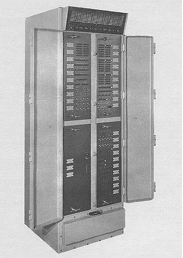 Photo by the UNIVAC Division, Sperry Rand Corp.
APPLICATIONS
General Purpose Computing
Multi-Computer in-line application
Range Instrumentation
Missile Guidance
Missile Fire Control
Simulation
Logistics
Message Switching
Ground Support Checkout
Navigation
Tactical Control
Telemetry
Digital Communications
Data Reduction and Analysis
Inventory and Scheduling
PROGRAMMING AND NUMERICAL SYSTEM
Internal number system Binary
Binary digits/word 18
Binary digits/instruction 18
Instructions/word 1
Instructions decoded 98 including 18 I/0
instructions
Arithmetic system Fixed point
Parallel, ones complement, subtractive arithmetic
is performed.
Instruction type One address
Number range ± 131,071 (17 bits + sign) and
± 34, 359 738, 367 (35 bits + sign)
Photo by the UNIVAC Division, Sperry Rand Corp.
APPLICATIONS
General Purpose Computing
Multi-Computer in-line application
Range Instrumentation
Missile Guidance
Missile Fire Control
Simulation
Logistics
Message Switching
Ground Support Checkout
Navigation
Tactical Control
Telemetry
Digital Communications
Data Reduction and Analysis
Inventory and Scheduling
PROGRAMMING AND NUMERICAL SYSTEM
Internal number system Binary
Binary digits/word 18
Binary digits/instruction 18
Instructions/word 1
Instructions decoded 98 including 18 I/0
instructions
Arithmetic system Fixed point
Parallel, ones complement, subtractive arithmetic
is performed.
Instruction type One address
Number range ± 131,071 (17 bits + sign) and
± 34, 359 738, 367 (35 bits + sign)
| BRL 1964, UNIVAC 1218, starting page 0292
|
    Instruction word format
               +--------------------------+
    FORMAT I   | 17    12 | 11          0 |
               +----------+---------------+
               |  f       |  u            |
               +----------+---------------+
               +----------+---------------+
    FORMAT II  | 17    12 | 11  6 | 5   0 |
               +----------+---------------+
               |  f       |  m    |  k    |
               +----------+---------------+

    f -   function code
    u -   operand address
    m -   minor function code
    k -   designator used for channel number, shift count,
            etc.

    Automatic built-in subroutines

    32 words of non-destructive read-out (NDRO) memory are furnished to
    provide initial load and error recovery routines.

    Automatic coding.

    No computer independent compiler is provided, however the TRIM III
    Assembly System provides for automatic generation of certain program
    sequences.

    Registers and B-Boxes

    The following are the addressable registers:
      1 AU - Register (Upper Accumulator, 18 bits)
      1 AL - Register (Lower Accumulator, 18 bits)
      1 ICR - Register (Index Control Register, 3 bits)
      1 SR - Register (Special, 4 bits)
      1 P - Register (Program address, 15 bits)

    The UNIVAC 1218 is essentially programmed for 4,096-word modules
    however each instruction that references memory is capable of
    addressing any other cell in memory.

    The UNIVAC 1218 has a complete repertoire of instructions that is
    especially generous in the control of I/0.

    Four instructions provide built-in double precision Add and Subtract.

                                  ARITHMETIC UNIT

            Incl. Stor. Access    Excl. Stor. Access
            Microsec              Microsec
    Add         8                     6
    Malt    26 - 48.7                --
    Div        48                    --
    Arithmetic mode    Parallel
    Timing             Synchronous
    Operation          Sequential/Parallel

    STORAGE

                         No. of            No. of     Access
     Medium              Words             Digits     Microsec
    Magnetic Core        4,096 - 32,768       18          1.8 access
                                                          4.0 cycle
    Magnetic Core (NDRO)*   32                18          4.0 cycle
    FH 880 Drum        786,432 words/drum     36         17 ms
                       (8 per channel)                (Average access)
    Magnetic tape
     No. of units that can be connected                    16 Units/channel
     No. of chars/linear inch               556 Chars/inch
     Channels or tracks on the tape           7 Track/tape
     Blank tape separating each record        0.75 Inches
     Tape speed                             112.5 Inches/sec
     Transfer rate                           62.5 Chars/sec
     Average time for experienced
    operator to change reel of tape          30   Seconds
    Physical properties of tape
      Width                                   0.5 Inches
      Length of reel                      2,400 Feet
      Composition                             Mylar

    The magnetic tape subsystem, Type 1240 is a fully compatible magnetic
    tape format at 200 or 556 chars/ inch. It has search and other special
    features.

    * Non-destructive read-out

      INPUT
    Medium                          Speed
    Card Reader             600 cards/min   (Commercial, 80 or 90
                                             column)
    Paper Tape              300 chars/sec   (5 to 8 level)
    Keyboard                       Manual   (Provides alphanumeric
                                            data entry)
    Teletype                 10 chars/sec
    Paper Tape and Keyboard are included in Programmers
    Console, Type 1232.

    OUTPUT

        Medium                      Speed
    High Speed Printer       600 lines/min(Commercial)
    Card Punch               150 cards/min  (Commercial 80 or
                              90 column)
    Paper Tape Punch         110 chars/sec  (5 to 8 level)
    Monitor Printer           10 chars/sec

    Paper Tape Punch and Monitor Printer are included in Programmers
    Console, Type 1232.

      CIRCUIT ELEMENTS OF ENTIRE SYSTEM
        Type                     Quantity
    Magnetic Cores           73,728 to 589,824
    Number of cores varies according to memory size, e.g., 73,728/4,096
    words of memory.

      CHECKING FEATURES

    Programmed parity checking.

     POWER, SPACE, WEIGHT, AND SITE PREPARATION

    Power, computer                  0.85   Kw
    Power, blowers                   0.15   Kw
    Volume, computer                 23.3   cu ft
    Area, computer                    3.9   sq ft
    Floor loading                     198   lbs/sq ft
                                      198   lbs concen max
    Ambient air cooled; equipment included in computer
    cabinet.
    Weight, computer                  775    lbs

    May be ship or van mounted. Does not require false floor. Power
    required is 115 V, 1 phase, 60 cycle and 115 V, 3 phase, 400 cycle.

    COST, PRICE AND RENTAL RATES

     Basic System/Component      Purchase
    Minimum 1218 Computer: 4k memory,
              4 I/0              $ 96,000
    Most common 1218 Computer:
             16K memory, 8 I/0    127,000
    Militarized Mag Tape System
             (2 handlers)          80,500
    Paper Tape Subsystem incl.
             keyboard & printer    25,000
    High speed printer system      77,500
    80 column card system          83,250

    Fixed price sale only on 1218 basic system.
| BRL 1964, UNIVAC 1218, starting page 0293
|
    RENTAL RATES
                            Monthly Lease
    UNISERVO IIA              $      450
    Control & Synchronizer         1,530
    Power Supply                     550
    High Speed Printer               500
    Control & Synchronizer         1,450
    Card Reader                      350
    Card Punch                       500

    Control & Synchronizer
        for Reader & Punch         1,600
    FH 880 Drum                    2,000
    Control and Synchronizer       1,420

     PERSONNEL REQUIREMENTS
                One 8-Hour Two 8-Hour Three 8-Hour
                Shift      Shifts     Shifts

    Supervisors   1         1          1
    Analysts      2         2          2
    Programmers   4         6          8
    Clerks        1         2          2
    Operators     1         1          1
    Technicians   On call   On call    On call

    Training made available by the manufacturer to the user includes
    programming and maintenance courses, held upon request at St. Paul,
    Minnesota and at the customer's site. Complete training and
    maintenance courses are available and UNIVAC Military Field
    Engineering service is available on a world-wide basis.

    RELIABILITY, OPERATING EXPERIENCE

     It is expected average meantime between failures
    (MTBF) will be in excess of 1,000 hours. The UNIVAC
    1218 was designed using MIL-E-16400D as a guide plus
    MIL-I-16910A, MIL-STD-108D, MIL-S-901, and MIL-STD-167

     ADDITIONAL FEATURES AND REMARKS

    Outstanding features include 8 I/0 channels, buffered input/output;
    any or all channels may by intercomputer; real-time interrupt s;
    powerful instruction repertoire.

    Unique system advantages include small physical size, resistant to
    shock, vibration, unusual climate conditions and radio frequency
    interference (RFI). Compatible with the Naval Tactical Data System
    (NTDS) peripheral equipment and can be direct cable-coupled to large
    scale UNIVAC computers.

    Designed to meet MIL-E-16400D
    Repertoire of 98 instructions
    Real time millisecond clock capability
    Average instruction time 8-12 microseconds
    Memory cycle time 4 microseconds

    Up to 8 Input and 8 Output channels; each may be intercomputer;
    channels may be paired to form 36-bit interface.

    All Input/Output transfers fully buffered

    33 distinct automatic interrupts standard with 8 I/0 channels

    32 words of permanent memory.

    The new UNIVAC 1218 Military Computer is a versatile stored program,
    medium scale, general purpose digital computer designed to provide
    high reliability under advance operational environments.

    With a core memory cycle time of 4 microseconds and powerful
    Input/Output features it is capable of processing large quantities
    of real time data.
| BRL 1964, UNIVAC 1824, starting page 0294
|
UNIVAC 1824
UNIVAC 1824 Microelectronic Aerospace Computer
MANUFACTURER
UNIVAC DIVISION, Sperry Rand Corp.
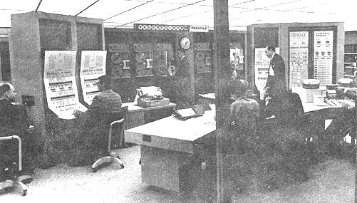 Photo by UNIVAC Division, Sperry Rand Corp.
APPLICATIONS
The UNIVAC Model 1824 Microelectronic Aerospace Computer is a high
performance, general purpose, airborne digital computer.
PROGRAMMING AND NUMERICAL SYSTEM
Internal number system Binary
Binary digits/word 24
Binary digits/instruction 16
Instructions/word 1
Instructions decoded 35
Arithmetic system Fixed point
Instruction type One address
Number range Fractional two's complement.
Instruction word format
+---------+--------+-------+-----------------+
| 5 Bits | 2 Bits | 1 Bit | 8 Bits |
+---------+--------+-------+-----------------+
| OP Code | Index | Ext | Operand Address |
+---------+--------+-------+-----------------+
Subroutine and interrupt capabilities are present in the system.
Photo by UNIVAC Division, Sperry Rand Corp.
APPLICATIONS
The UNIVAC Model 1824 Microelectronic Aerospace Computer is a high
performance, general purpose, airborne digital computer.
PROGRAMMING AND NUMERICAL SYSTEM
Internal number system Binary
Binary digits/word 24
Binary digits/instruction 16
Instructions/word 1
Instructions decoded 35
Arithmetic system Fixed point
Instruction type One address
Number range Fractional two's complement.
Instruction word format
+---------+--------+-------+-----------------+
| 5 Bits | 2 Bits | 1 Bit | 8 Bits |
+---------+--------+-------+-----------------+
| OP Code | Index | Ext | Operand Address |
+---------+--------+-------+-----------------+
Subroutine and interrupt capabilities are present in the system.
| BRL 1964, UNIVAC 1824, starting page 0295
|
    Automatic coding
    A program, for the UNIVAC 1824, may be assembled on the
    UNIVAC 1206, which, by means of an interpreter, may be run
    on the UNIVAC 1206 also.

    The Registers and B-Boxes that are programmable are 3 B-
    Boxes as fixed addresses in DRO Memory, a 48-bit
    accumulator, and Input/Output registers.

    ARITHMETIC UNIT
           Incl. Stor. Access   Excl. Stor. Access
           Microsec             Microsec
    Add        8                   4
    Mult    44 - 84               40 - 80
    Div       124                120

    Construction (Arithmetic unit only)
    750 integrated semiconductor circuits.
    Arithmetic mode    Parallel
    Timing             Synchronous
    Operation          Sequential

    STORAGE

                      No. of     No. of       Access
    Medium            Words      Bits/Word    Microsec

    Thin Film (DRO)     512           2           1.0
    Thin Film (NDRO)  8,192          24           1.0

     DRO - Destructive Read-Out
    NDRO - Non-destructive Read-Out

    INPUT
    Medium             Speed
    Paper Tape      250 or 500 chars/sec
    Keyset Entry    Manual (numeric)

    OUTPUT
     Medium            Speed
    Paper Tape      110 chars/sec
    Printer       1,040 lines/min
    Recording Equipment                     Dependent upon application

    Special purpose input/output characteristics for aerospace
    application is utilized when the computer is mounted in
    weapon systems. The computer is operated through its
    support equipment console. Its operation is analogous to the
    operation of a typical general purpose computer.

    CIRCUIT ELEMENTS OF ENTIRE SYSTEM
    Type               Quantity
    Tubes                   0
    Diodes                  0
    Transistors             0
    Microelectronic Integrated
     Circuits           2,177
    Magnetic Cores          0

    The computer uses semiconductor integrated circuits and
    magnetic thin film memories. The total number of circuits
    depends upon I/0 requirements and memory size. The central
    computer including arithmetic and control and memory are
    indicated in the above table.

   POWER, SPACE, WEIGHT, AND SITE PREPARATION
    Power, computer    0.1 Kw
    Volume, computer   0.5 cu ft
    Floor loading     32.15 lbs concen max
    Weight, computer  32.15 lbs
    Site preparation requirements

    An air conditioner is not required for the computer.
    Primary power is 28 V DC.

    Size and weight includes central computer, memory system,
    full missile system and stellar tracker interface, and a self
    contained power supply.

    RELIABILITY, OPERATING EXPERIENCE

    The techniques employed in the design, range from the basic
    integrated circuitry to the connectorless final assembly.

    The equipment support requirement, the cost of which often
    exceeds that of the original equipment by several times, is
    reduced drastically.

    A field maintenance philosophy, in which the complete
    computer can be changed as a unit, can be adopted because of
    the high reliability and small physical size. The need for
    highly trained technicians in the field is thereby virtually
    eliminated. On the other hand, depot repairs can be
    conducted to the level of a single low-cost chip or logic
    element.

     ADDITIONAL FEATURES AND REMARKS

    Outstanding features include small size, weight and power
    requirements, medium speed, and high reliability.

    Unique system advantages include full solid state
    microelectronic circuits, a thin film memory computer with
    general purpose characteristics makes the computer highly
    versatile for complex system application.

    The computer features the latest advances in microelectronic
    circuits, metallic thin film memories, and multilayer,
    photoetched interconnections. It is designed for simple and
    inexpensive fabrication and for reliable operation under
    severe environmental conditions. It is particularly suited for
    application as a guidance and control unit within complex
    aerospace systems. While the design is characterized by a
    maximum packaging density, the computer retains full access
    for ready maintenance.

    The high capability and general purpose logic of the computer
    assures a large margin of safety in meeting most of the
    computational requirements of contemporary and planned
    aerospace systems. A logical system growth potential is thus
    available by the addition of appropriate interface and memory
    storage capacity. Additionally the basic computer has a
    sufficiently small size, weight, and power requirement so that
    modular expansion of the input/output or storage capacity,
    imposed by advanced or increased requirements, minimizes
    the size increase and would not encroach appreciably upon
    predetermined physical constraints.

    The computer is sealed in a case. No particular protection is
    required.

    A unique interface design is required for each different
    application of the computer. The computer is intended to
    have a fully integrated interface in one integral structure
    without the necessity of system connection through special
    interface boxes.

    FUTURE PLANS

    The storage capacity may be varied as a modification
    dependent upon system storage requirements.
| BRL 1964, UNIVAC DIG TRNR, starting page 0296
|
UNIVAC DIG TRNR
UNIVAC Digital Trainer
MANUFACTURER
UNIVAC, Division of Sperry Rand Corp. UNIVAC Park, St Paul, Minnesota
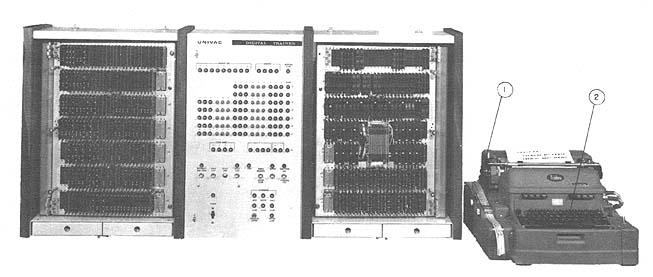 (1) Tape Punch and Reader, (2) Keyboard Photo by UNIVAC
APPLICATIONS
The UNIVAC Digital Trainer is a compact general purpose digital computer packaged for
training programmers and maintenance technicians. It is parallel, solid state computer
with magnetic core memory and a full repertoire of instructions including one index
register (B-Box).
PROGRAMMING AND NUMERICAL SYSTEM
Internal number system Binary
Binary digits/word 15, including sign
Instructions/word 1
Instructions decoded
Go-instruction repertoire including all variations
to basic instructions.
Arithmetic system Fixed point
Instruction type One address
Number range ±215- 1
+-----------------------+--------------------------+
| Upper 6 Bits | Lower 9 Bits |
+-----------------------+--------------------------+
| Instruction or Index | Direct addressing to |
| Register Modifiers | 512 words of core memory |
+-----------------------+--------------------------+
Automatic coding
Basic mnemonic to octal translator are available. Some relative addressing. Basically,
however, this unit is programmed in octal.
Registers and B-Boxes
1 B-Box at storage location zero has:
15 Bit Accumulator 15 Bit D Register
15 Bit 0 Register 15 Bit D Register
15 Bit X Register 9 Bit P Register
15 Bit D Register 9 Bit S Register
6 Bit U Register
All Registers except the B Index Register are visible on the panel.
ARITHMETIC UNIT
Incl. Stor. Access Excl. Stor. Access
Microsec Microsec
Add 24 8
Mult 130
Div 130
Construction (Arithmetic unit only)
Transistor diode negative 'ors logic (NOR) is used.
Arithmetic mode Parallel
Timing Synchronous
Operation Sequential
STORAGE
No. of No. of Access
Words Alphan Char. Microsec
Core Storage 512 Bin. Approx 1,000 2.5
(Flexowrite 6-Bit)
INPUT
Medium Speed
Paper Tape (Flexowriter) 10 chars/sec
Flexowriter Keyboard 10 chars/sec
Control Panel Lights 2 chars/sec
OUTPUT
Medium Speed
Paper Tape (Flexowriter) 10 chars/sec
Flexowriter Keyboard 10 chars/sec
Panel Lights - -
This unit is primarily a training computer. Cost was a prime consideration in design
and development of the computer. Due to the relatively high cost of tape handlers, high
speed printers, etc., these units are not included as a part of the system.
(1) Tape Punch and Reader, (2) Keyboard Photo by UNIVAC
APPLICATIONS
The UNIVAC Digital Trainer is a compact general purpose digital computer packaged for
training programmers and maintenance technicians. It is parallel, solid state computer
with magnetic core memory and a full repertoire of instructions including one index
register (B-Box).
PROGRAMMING AND NUMERICAL SYSTEM
Internal number system Binary
Binary digits/word 15, including sign
Instructions/word 1
Instructions decoded
Go-instruction repertoire including all variations
to basic instructions.
Arithmetic system Fixed point
Instruction type One address
Number range ±215- 1
+-----------------------+--------------------------+
| Upper 6 Bits | Lower 9 Bits |
+-----------------------+--------------------------+
| Instruction or Index | Direct addressing to |
| Register Modifiers | 512 words of core memory |
+-----------------------+--------------------------+
Automatic coding
Basic mnemonic to octal translator are available. Some relative addressing. Basically,
however, this unit is programmed in octal.
Registers and B-Boxes
1 B-Box at storage location zero has:
15 Bit Accumulator 15 Bit D Register
15 Bit 0 Register 15 Bit D Register
15 Bit X Register 9 Bit P Register
15 Bit D Register 9 Bit S Register
6 Bit U Register
All Registers except the B Index Register are visible on the panel.
ARITHMETIC UNIT
Incl. Stor. Access Excl. Stor. Access
Microsec Microsec
Add 24 8
Mult 130
Div 130
Construction (Arithmetic unit only)
Transistor diode negative 'ors logic (NOR) is used.
Arithmetic mode Parallel
Timing Synchronous
Operation Sequential
STORAGE
No. of No. of Access
Words Alphan Char. Microsec
Core Storage 512 Bin. Approx 1,000 2.5
(Flexowrite 6-Bit)
INPUT
Medium Speed
Paper Tape (Flexowriter) 10 chars/sec
Flexowriter Keyboard 10 chars/sec
Control Panel Lights 2 chars/sec
OUTPUT
Medium Speed
Paper Tape (Flexowriter) 10 chars/sec
Flexowriter Keyboard 10 chars/sec
Panel Lights - -
This unit is primarily a training computer. Cost was a prime consideration in design
and development of the computer. Due to the relatively high cost of tape handlers, high
speed printers, etc., these units are not included as a part of the system.
| BRL 1964, UNIVAC DIG TRNR, starting page 0297
|
    Photo by UNIVAC

    The computer operator is stepping through the student's program,
    one instruction at a time. Program status is displayed on the
    register lights (1) on the control panel. This program was
    loaded via the automatic typewriter tape reader into the core memory (2).
    The program can be corrected by manual insertions of new data
    at the control console. Once operational, the corrected program tape
    will be  punched out and printed automatically at the Input/Output
    typewriter (3).

    CIRCUIT ELEMENTS OF ENTIRE SYSTEM

       Type           Quantity
    Tubes                   0
    Diodes              5,000 (Approx.)
    Transistors         1,200 (Approx.)
    Magnetic Cores        512-15 bit words

    All solid state construction.

    CHECKING FEATURES
    Operations such as add, multiply, etc. may be program checked.
    Input and output is via lower 6 bits of the "Q" Register.

    POWER, SPACE, WEIGHT, AND SITE PREPARATION
    Power, computer     0.7 Kw        0.8 KVA   0.8-0.9 pf
      115 Volt, 60 cps

    Volume, computer      8 cu ft
    Area, computer        3.6 sq ft
    Room size - Nominal  10' x     10, x 10'
    Weight, computer    400 lbs
    Site preparation is not required except table and 115 Volt
    60 cps power, 700 watts. Flexowriter is not included in above space
    requirements.

    No air conditioning required except ambient room temperature
     should be less than 85o F.

                                 PRODUCTION RECORD
    Number produced to date         24
    Number in current operation     19
    Number in current production     8
    Number on order                 28
    Anticipated production rates     2 - 4 per month
    Time required for delivery       5 months maximum

    COST, PRICE AND RENTAL RATES
    Computer unit, Flexowriter and three week training course. $35,000
    Unconditional guarantee first thirty days, conditional
    guarantee for ninety days. Thereafter, service on an
    "on call" basis will be billed.

    PERSONNEL REQUIREMENTS
    The system trains personnel as follows:

                  One 8-Hour  Two 8-Hour
                    Shift     Shifts
    Programmers    15 - 20   30 - 40
    Operators         1         1
    Technicians     6 - 12   12 - 24

    Three week UNIVAC course included with each computer. Course
    stresses programming logic and maintenance for customer personnel at
    customers site.

    This device is primarily for training of computer programmers
    and technicians. The "operator" is equivalent to an instructor and the
    "programmers" to students learning basic or intermediate programming
    techniques. "Technicians" are equivalent to trainees in
    maintenance techniques.

     RELIABILITY, OPERATING EXPERIENCE
    All solid state. Design based on logic developed for military
    computers. Estimated at over 100 hours mean-time-to-failure.

                                ADDITIONAL FEATURES

    Outstanding features include low relative cost. Completely
    parallel logic, and very fast magnetic core memory, typical of most
    large-scale, high-speed systems.

    The system is packaged for access to all logic components
    and it has a full-size operator/control
| BRL 1964, UNIVAC DIG TRNR, starting page 0298
|
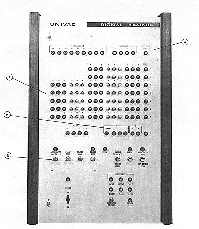 Photo by UNIVAC
(1) Arithmetic, control and memory access registers.
(2) Program control register.
(3) Switches for full control over the computer operation.
(4) Timing sequence indicators.
Unique system advantages include a complete instruction repertoire,
full scale operator/control panel, paper tape, and keyboard I/0,
packaged for programmer maintenance technician training mission
and suitable for classroom use.
The UDT is the general purpose, binary, high speed computer-designed
especially for training within the military agencies. It is
currently in use by all three service branches at various
technical training centers and schools.
FUTURE PLANS
A capability for faster paper tape input (300 frames sec).
Modification of a spec 15 bit I/0 channel adapter to allow two Digital
Trainer computers to transfer data under program control,
thus simulating the more complex dual computer system operation.
REMARKS
UNIVAC Digital Trainers are currently in use in all three branches
of the military. Current Orders are as follows:
13 for the U.S. Navy (7 delivered)
5 for the U.S. Army (5 delivered)
10 for the U.S. Air Force (6-delivered)
Current commitments for 28 units will be completed by 15 September 1963.
INSTALLATIONS
Redstone Arsenal OGMS School (4 machines)
Bainbridge (Later trfd to Westinghouse in Maryland by Navy)
Mare Island (Navy) (4 machines)
Keesler Air Force Base TTC (3 machines)
Sheppard Air Force Base (2 machines plus 1 on loan
until May 63 for reshipment to Glynco)
Great Lakes (Navy) (2 machines)
Fort Bliss Air Defense School
    Photo by UNIVAC

    (1) Arithmetic, control and memory access registers.
    (2) Program control register.
    (3) Switches for full control over the computer operation.
    (4) Timing sequence indicators.

    Unique system advantages include a complete instruction repertoire,
    full scale operator/control panel, paper tape, and keyboard I/0,
    packaged for programmer maintenance technician training mission
    and suitable for classroom use.

    The UDT is the general purpose, binary, high speed computer-designed
    especially for training within the military agencies. It is
    currently in use by all three service branches at various
    technical training centers and schools.

     FUTURE PLANS
    A capability for faster paper tape input (300 frames sec).
    Modification of a spec 15 bit I/0 channel adapter to allow two Digital
    Trainer computers to transfer data under program control,
    thus simulating the more complex dual computer system operation.

    REMARKS
    UNIVAC Digital Trainers are currently in use in all three branches
    of the military. Current Orders are as follows:
      13 for the U.S. Navy (7 delivered)
       5 for the U.S. Army (5 delivered)
      10 for the U.S. Air Force (6-delivered)

    Current commitments for 28 units will be completed by 15 September 1963.

    INSTALLATIONS
    Redstone Arsenal OGMS School (4 machines)
    Bainbridge (Later trfd to Westinghouse in Maryland by Navy)
    Mare Island (Navy) (4 machines)
    Keesler Air Force Base TTC (3 machines)
    Sheppard Air Force Base (2 machines plus 1 on loan
       until May 63 for reshipment to Glynco)
    Great Lakes (Navy) (2 machines)
    Fort Bliss Air Defense School
| BRL 1964, UNIVAC DIG TRNR, starting page 0299
|
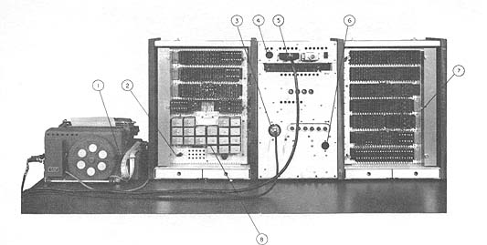 UNIVAC Digital Trainer (Rear View) Photo by UNIVAC
(1) The student's program tape ready for read-in.
(2) A built-in logic card tester
(3) 115 volt, 60 cycle input line for the computer and typewriter system.
(4) Connector for input power line (computer-to-typewriter)
(5) Data cable (typewriter-to-computer)
(6) 115 volt, 60 cycle convenience outlet for oscilloscope and other test equipment.
(7) Test signal blocks (easily available test points for monitoring
of electrical voltages and pulses via oscilloscopes and meters)
(8) Relay banks for transfer of computer data to and from
the input-output typewriter.
UNIVAC Digital Trainer (Rear View) Photo by UNIVAC
(1) The student's program tape ready for read-in.
(2) A built-in logic card tester
(3) 115 volt, 60 cycle input line for the computer and typewriter system.
(4) Connector for input power line (computer-to-typewriter)
(5) Data cable (typewriter-to-computer)
(6) 115 volt, 60 cycle convenience outlet for oscilloscope and other test equipment.
(7) Test signal blocks (easily available test points for monitoring
of electrical voltages and pulses via oscilloscopes and meters)
(8) Relay banks for transfer of computer data to and from
the input-output typewriter.
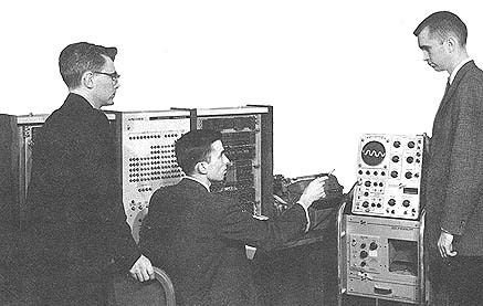 Photo by UNIVAC
The oscilloscope is connected via a front test block
(not visible) in order to show the stage of the MEMORY
INHIBIT flip-flop within the computer.
Photo by UNIVAC
The oscilloscope is connected via a front test block
(not visible) in order to show the stage of the MEMORY
INHIBIT flip-flop within the computer.
| BRL 1964, UNIVAC DIG TRNR, starting page 0300
|
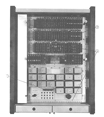 UNIVAC Digital Trainer (Left Section-Rear View) Photo by UNIVAC
(1) Built-in card tester.
(2) A marginal check on the computer system components
may be initiated by moving this card one position.
(3) Specific logic card located physically.
UNIVAC Digital Trainer (Left Section-Rear View) Photo by UNIVAC
(1) Built-in card tester.
(2) A marginal check on the computer system components
may be initiated by moving this card one position.
(3) Specific logic card located physically.
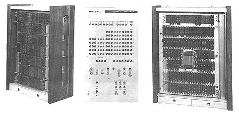 UNIVAC Digital Trainer (Ready for Shipment) Photo by UNIVAC
| BRL 1964, UNIVAC DIG TRNR, starting page 0301
|
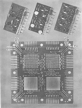 Photo by UNIVAC
The three types of logic circuits and one of the fifteen magnetic core memory planes.
    Photo by UNIVAC

    The three types of logic circuits and one of the fifteen magnetic core memory planes.
| BRL 1964, UNIVAC SOLID STATE II 80/90, starting page 0302
|
UNIVAC SOLID STATE II 80/90
MANUFACTURER
UNIVAC , Division of Sperry Rand Corp.
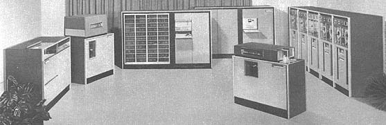 Photo by UNIVAC
APPLICATIONS
System is designed as a general purpose data processing
system for use in general accounting, inventory,
billing, budget control, sales analysis, statistics,
railroad accounting, and revenue accounting, as well as
scientific computing. The UNIVAC Solid-State Computer
is a medium-priced data processing system for
business use. The term "Solid-State" refers to the use
of Ferractor amplifiers and transistors. The Solid-State
consists of a central processor, a readpunch unit, a
high-speed card reader and a high-speed printer.
Automatic coding techniques simplify programming.
The Solid-State system may be ordered with magnetic
tape units for either the 90-column system or the
80-column system.
PROGRAMMING AND NUMERICAL SYSTEM
Internal number system Binary coded decimal
Decimal digits/word 10 plus sign
Decimal digits/instruction 10
Instructions/word 1
Instructions decoded 76
Arithmetic system Fixed point
Instruction type One and a half address
One address is the operand - the half address refers to the
address of next instruction to be executed. Next
instruction is the (c) portion of the instruction.
Number range -9999999999 to +9999999999
Instruction word format
+-------------+-------------+-------------+
| Instruction | (m) Address | (c) Address |
| Code | | |
+------+------+---+---+--+--+---+---+--+--+
| | | | | | | | | | |
+------+------+---+---+--+--+---+---+--+--+
(m) Address is address of operand
(c) Address is the address of the next instruction
to be executed.
A sizable number of precoded routines are supplied to
Solid State Computer users. Approximate 58 routines
available for 80-column tape system, and 62 available
for 90-column tape system.
Automatic coding includes an X-6 assembly available
for card and tape system, FORTRAN II, S4 Assembly
system, Report Generator, PROGENY, and a variety
of utility programs. A program interrupt feature is
optionally available on both Model I and Model II.
Registers and B-Boxes
3-10 digit arithmetic registers
9 - index registers (4 digits each) are standard.
ARITHMETIC UNIT
Incl. Stor. Access Excl. Stor. Access
Microsec Microsec
Add 136 (b = b + a) 51
Mult 688 (5-dig product) 569 (5-dig product)
Div 1,173 (average) 1,054 (average)
Photo by UNIVAC
APPLICATIONS
System is designed as a general purpose data processing
system for use in general accounting, inventory,
billing, budget control, sales analysis, statistics,
railroad accounting, and revenue accounting, as well as
scientific computing. The UNIVAC Solid-State Computer
is a medium-priced data processing system for
business use. The term "Solid-State" refers to the use
of Ferractor amplifiers and transistors. The Solid-State
consists of a central processor, a readpunch unit, a
high-speed card reader and a high-speed printer.
Automatic coding techniques simplify programming.
The Solid-State system may be ordered with magnetic
tape units for either the 90-column system or the
80-column system.
PROGRAMMING AND NUMERICAL SYSTEM
Internal number system Binary coded decimal
Decimal digits/word 10 plus sign
Decimal digits/instruction 10
Instructions/word 1
Instructions decoded 76
Arithmetic system Fixed point
Instruction type One and a half address
One address is the operand - the half address refers to the
address of next instruction to be executed. Next
instruction is the (c) portion of the instruction.
Number range -9999999999 to +9999999999
Instruction word format
+-------------+-------------+-------------+
| Instruction | (m) Address | (c) Address |
| Code | | |
+------+------+---+---+--+--+---+---+--+--+
| | | | | | | | | | |
+------+------+---+---+--+--+---+---+--+--+
(m) Address is address of operand
(c) Address is the address of the next instruction
to be executed.
A sizable number of precoded routines are supplied to
Solid State Computer users. Approximate 58 routines
available for 80-column tape system, and 62 available
for 90-column tape system.
Automatic coding includes an X-6 assembly available
for card and tape system, FORTRAN II, S4 Assembly
system, Report Generator, PROGENY, and a variety
of utility programs. A program interrupt feature is
optionally available on both Model I and Model II.
Registers and B-Boxes
3-10 digit arithmetic registers
9 - index registers (4 digits each) are standard.
ARITHMETIC UNIT
Incl. Stor. Access Excl. Stor. Access
Microsec Microsec
Add 136 (b = b + a) 51
Mult 688 (5-dig product) 569 (5-dig product)
Div 1,173 (average) 1,054 (average)
| BRL 1964, UNIVAC SOLID STATE II 80/90, starting page 0303
|
    Arithmetic mode    Serial
     Serial by digit, parallel by bit.
     The word time is 17 microseconds.
    Timing             Synchronous
    Operation          Concurrent

    STORAGE
                     No. of      No. of Dec.       Access
     Medium          Words       Digits            Microsec
    Magnetic Core   1,280        14,080              17
    Magnetic Drum     200-1,200   2,000-12,000      425
    Magnetic Drum   2,400-7,600  24,000-76,000    1,700
    Magnetic Tape
    No. of units that can be connected       20 Units
    No. of chars/linear inch of tape        250 Chars/inch
    Channels or tracks (8 incl sprocket)      7 Track/tape
    Blank tape separating each record         1.05 Inches
    Tape speed                              100 Inches/sec
     Transfer rate                       25,000 Chars/sec
     Start time                              12 Millisec
     Stop time                                9 Millisec
     Average time for experienced
    operator to change reel of tape          30 Seconds
    Up to 20 tape units are connectable through the use of a
    second synchronizer. Physical properties of tape
    Width                                     0.5015+0.0000-0.0030 Inches
    Length of reel                        2,500             Feet
    (Recording surface)
    Composition                               Mylar

    All users have the 5,000 word drum. Standardized system
    comparison for formula[ (A+B)'C ] /D 4 Memory requires 1.19
    milliseconds.

         INPUT
    Medium             Speed
    High Speed Card Reader  450 cards/min
    Read-Punch Card Unit    150 cards/min
    Magnetic Tape           100 inches/sec
     No plugboard is used.   80 or 90-column card units
    are available. Tape densities and formats are com-
    patible with other UNIVAC tape systems.

        OUTPUT
    Medium             Speed
    Read-Punch Card Unit    150 cards/min
    Magnetic Tape           100 inches/sec
    High Speed Printer      600 lines/min
    Card Punching Printer   150 cards/min

    Printer prints 130 chars/line. Card Punching Printer prints
    on both sides of Tab Card - a maximum of 13 lines on a side.
    Instantaneous printing rate is 900 lines/minute.

       CHECKING FEATURES

    Odd parity, overflow, complete tape read checks.

    Two read stations in card equipment. Logical checks in
    central processor and printer.

    POWER, SPACE, WEIGHT, AND SITE. PREPARATION
    Power, computer    50.7 KVA    0.8 pf
    Includes Printer Punch, Reader, 10 Servos, and Core
    Memory.
    Area, computer     925 sq ft
    Capacity, air conditioner               12.3 Tons
    Weight, computer  3,532 lbs
    Site preparation requirements
    Cable duct work is supplied with computer, if desired.

    No special flooring is required. Power includes printer,.
    punch, reader and 10 servos.

   PRODUCTION RECORD

    Number produced to date                      31
    Number in current operation                  27
    Time required for delivery                   8 months

    PERSONNEL REQUIREMENTS
                      One 8-Hour  Two 8-Hour  Three 8-Hour
                      Shift       Shifts      Shifts
    Supervisors         2          2             3
    Analysts       A   supervisory function
    Program-Coders      5          5             5
    Clerks              3          3             3
    Librarians          1          1             1
    Operators           2          4             6
    Engineers           1          1             1
    Technicians         1          2             3

    Programming courses are supplied on a regional basis.

    RELIABILITY, OPERATING EXPERIENCE

    A preventive maintenance check is made by service engineer
    at start of each working day.

    ADDITIONAL FEATURES AND REMARKS

    Outstanding features include multiword transfers-drum-to-
    core and core-to-drum), six additional index registers, and
    full alphanumeric compare.

    Program interrupt is optional, a second synchronizer is
    available for simultaneous operations. The following
    operations can progress simultaneously: processing, card
    reading (high-speed reader), reading or punching paper tape,
    printing a line of data, reading or punching (read-punch
    unit), reading or writing a block of tape data or a block of
    Randex Data.

    If two synchronizers are employed, reading and writing on
    tape can also proceed simultaneously.

    The Model II Solid State System, like the Model I, is a
    medium-priced system capable of handling a wide range of
    data processing applications. Characterized by a main
    memory composed of both magnetic drum and magnetic core,
    it is fully buffered, allowing for efficient simultaneous
    input/output computer operations. Although the system is
    tape-oriented, an online card reader, a read/punch unit, as
    well as printer may be included.

    A basic Modell II central processor includes 14,080 digits of
    core storage and 2,600 words of drum storage, as well as 9
    index registers. As far as input/output devices are
    concerned, a minimum system may be expanded to include
    20 tape units, a card reader, a card read/punch unit, and a
    high-speed printer. Also, a maximum of ten Randex drum
    storage units may be included, each unit of which has a
    capacity of 24 million digits.

    A system including the basic processor, four tape units, and
    a printer rents for 6,970.00. "Typical" systems rent for
    approximately $8,500.00.

    A complete software package is available which includes: an
    Assembly System S4, FORTRAN II Algebraic Compiler, a
    Report Generator PROGENY, and a variety of Utility
    Programs.
| BRL 1964, UNIVAC SOLID STATE II 80/90, starting page 0304
|
| BRL 1964, UNIVAC SOLID STATE II 80/90, starting page 0305
|
| BRL 1964, VERDAN II, starting page 0306
|
VERDAN II
MANUFACTURER
Autonetics Division of North American Aviation
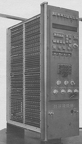 Photo by Autonetics Division
APPLICATIONS
The computer is designed primarily for solving real time control
problems by combining, under program control, a general purpose
computer and two digital differential analyzer sections. The
computer can be used as the central computer in control and
weapons systems. It has the capability of simultaneously
extrapolating points along many functions, computing new initial
conditions, accepting and processing time varying data from 90
different sources, and con
trolling 47 different output devices. The GP and DDA sections
operate simultaneously and independently, however the DDA program
can be controlled, monitored, and modified by the GP section under
GP program control.
PROGRAMMING AND NUMERICAL SYSTEM
Internal number system Binary
Binary digits/word 27
Binary digits/instruction 24
Photo by Autonetics Division
APPLICATIONS
The computer is designed primarily for solving real time control
problems by combining, under program control, a general purpose
computer and two digital differential analyzer sections. The
computer can be used as the central computer in control and
weapons systems. It has the capability of simultaneously
extrapolating points along many functions, computing new initial
conditions, accepting and processing time varying data from 90
different sources, and con
trolling 47 different output devices. The GP and DDA sections
operate simultaneously and independently, however the DDA program
can be controlled, monitored, and modified by the GP section under
GP program control.
PROGRAMMING AND NUMERICAL SYSTEM
Internal number system Binary
Binary digits/word 27
Binary digits/instruction 24
| BRL 1964, VERDAN 11, starting page 0307
|
    Instructions/word                   1 + next instruction address
    Instructions decoded
        The second address is the address of the next instruction.

    Arithmetic system                  Fixed point
    Instruction type                   Operand sector & channel
                                         + next instruction sector
    Number range                       ± 8,388,607 (Fractional)
    Instruction word format
    +---------+-------------+-----------+----------------+
    | 24   22 | 21       16 | 15     11 | 10          1  |
    +---------+-------------+-----------+----------------+
    | operand | next        | operation | operand        |
    | address | instruction | code      | address        |
    |         |             |           | channel sector |
    +---------+-------------+-----------+----------------+

    Registers and B-Boxes
     1 - 25-bit Intercomm. Buffer Register
     2 - Rapid Access Registers, 8-word, 16-word
     4 - Arithmetic Registers

    ARITHMETIC UNIT
                    Incl. Stor. Access
                    Microsec
    Add                78
    Mult            2,000
    Div             2,000
    Arithmetic mode       Serial
    Timing                Synchronous
    Operation             Sequential

    STORAGE
                      No. of   No. of Binary      Access
     Medium           Words    Digits             Microsec
    Magnetic Disk     5,632    135,168               156

    INPUT
    Medium                   Speed              Remarks
    Discrete (20)        Variable 1,000      (Read under GP pro-
                         pulses/sec max.         gram control)
    Resolver             Variable 1,000      (DDA program control)
                          cycles/sec
    Pulse                100 pulses/sec      (DDA program control)
    Analog               Continuous          (DDA program control)
    Encoder              Continuous          (DDA program control)

    Operator inputs are keyboard, typewriter, or punched tape.

    OUTPUT
       Medium                Speed/second       Remarks
    GP channel & timing     345,600 cycles   (Continuous)
    Discrete (8)                100 pulses   (Control external
                                                devices)
    Incremental (Binary)        100 pulses   (DDA information)
    Incremental (Ternary)       100 pulses   (DDA information)
    Analog                       Continuous
      Two format options, 20-bit precision.
    Shaft Positioning            Continuous

    Operator outputs are the Nixie display of any memory location
    by setting up of location selection switches, the display of
    continuous output either manual or programmed, typewriter,
    or punched paper tape.

    POWER, SPACE, WEIGHT, AND SITE PREPARATION
    Power, computer             0.925 KV.
    Volume, computer            3.0 cu ft
    Weight, computer              180 lbs

    PRODUCTION RECORD
    Number produced to date            61
    Number in current operation        33
    Number in current production       49
    Number on order                   110
    Anticipated production rates        4/week
    Time required for delivery          7 months

    PERSONNEL REQUIREMENTS
    Maintenance training and operation training rendered as
    required.