Go To Table of Contents
| BRL 1964, starting page 0013
|
CHAPTER II

COMPUTING SYSTEMS DESCRIPTION
| BRL 1964, AERIS, starting page 0014
|
AERIS
CUBIC AERIS

MANUFACTURER
Cubic Corporation


Photo by the Cubic Corporation

APPLICATIONS
	The Cubic DH-59 is an on-line, real-time general purpose
computer. It receives on-line input of range data from MME
equipment and on-line outputs X, Y, Z, and H to D/A converters for
graph plotting and B/BCD converters for print-out. This output data
is used for real-time guidance.
PROGRAMMING AND NUMERICAL SYSTEM
Internal number system	        Binary
Binary digits/word              21
Binary digits/instruction       23
Instructions/word                1
Instructions decoded            31
Arithmetic system               Fixed point
                                Sign plus magnitude
Instruction type                One-over-one
Number range          ± (1 - 2-21)

+-------+---------------+-----------+-------+-----------+
| 3 2 1 | 7 6 5 4 3 2 1 | 5 4 3 2 1 | 3 2 1 | 5 4 3 2 1 |
+-------+---------------+-----------+-------+-----------+
| Track |  Sector       |  Command  | Track |  Sector   |
| Next  |  Next         |           | Oper- | Operand   |
| Instr.|  Instr.       |           | and   |           |
+-------+---------------+-----------+-------+-----------+

	The computer was programmed at the factory for special
field use by the customer.

ARITHMETIC UNIT
        Excl. Stor. Access
           Microsec
Add          130
Mutt       2,860
Div        2,730
Construction (Arithmetic unit only
 Transistor HAND, and NOR gates and flip-flops, using type
2N1754, 2N404 transistors.
Arithmetic mode	Serial
Photo by the Cubic Corporation
APPLICATIONS
The Cubic DH-59 is an on-line, real-time general purpose
computer. It receives on-line input of range data from MME
equipment and on-line outputs X, Y, Z, and H to D/A converters for
graph plotting and B/BCD converters for print-out. This output data
is used for real-time guidance.
PROGRAMMING AND NUMERICAL SYSTEM
Internal number system Binary
Binary digits/word 21
Binary digits/instruction 23
Instructions/word 1
Instructions decoded 31
Arithmetic system Fixed point
Sign plus magnitude
Instruction type One-over-one
Number range ± (1 - 2-21)
+-------+---------------+-----------+-------+-----------+
| 3 2 1 | 7 6 5 4 3 2 1 | 5 4 3 2 1 | 3 2 1 | 5 4 3 2 1 |
+-------+---------------+-----------+-------+-----------+
| Track | Sector | Command | Track | Sector |
| Next | Next | | Oper- | Operand |
| Instr.| Instr. | | and | |
+-------+---------------+-----------+-------+-----------+
The computer was programmed at the factory for special
field use by the customer.
ARITHMETIC UNIT
Excl. Stor. Access
Microsec
Add 130
Mutt 2,860
Div 2,730
Construction (Arithmetic unit only
Transistor HAND, and NOR gates and flip-flops, using type
2N1754, 2N404 transistors.
Arithmetic mode Serial
| BRL 1964, AERIS, starting page 0015
|
 Digitizer and Range Memory Photo by the Cubic Corporation
Timing Synchronous
Operation Concurrent
The computer is organized on a parallel execute command
and search next operand and search next
instruction basis.
STORAGE
No. of No. of Access
Medium Words Digits Microsec
Drum 1,024 24,576 8,300
Drum Fast Access 128 1,536 2,080
Drum Scratch Pad 64 3,072 1,040
INPUT
Medium Speed
Digitizer 5 microsec/bit
On-line (part of DME system
OUTPUT
Medium Speed
D/A Converter 5 microsec/bit
B/BCD Converter 5 microsec/bit
Both units are used on-line
CIRCUIT ELEMENTS OF ENTIRE SYSTEM
Type Quantity
Diodes 4,500
Transistors 1,500
Approximately 180 modules
CHECKING FEATURES
Control panel displays all FFs. ALI registers accessible for
display. Single step operation mode.
POWER, SPACE, WEIGHT, AND SITE PREPARATION
Power, computer 0.25 Kw
Volume, computer logic 3.7 cu ft
Volume, computer drum 3.7 cu ft
Weight, computer logic 90 lbs
Weight, computer drum 120 lbs
PRODUCTION RECORD
Number produced to date 1
Number in current operation 1
Time required for delivery 10 months
Digitizer and Range Memory	Photo by the Cubic Corporation

Timing		Synchronous
Operation	Concurrent
  The computer is organized on a parallel execute command
and search next operand and search next
instruction basis.

 	STORAGE
			No. of No. of		Access
  Medium		Words	Digits	Microsec
Drum			1,024		24,576	8,300
Drum Fast Access	128	1,536	2,080
Drum Scratch Pad	64	3,072	1,040

	INPUT
 Medium			Speed
Digitizer	5 microsec/bit
On-line (part of DME system

	OUTPUT
		Medium	Speed
D/A Converter	5 microsec/bit
B/BCD Converter	5 microsec/bit
Both units are used on-line

	CIRCUIT ELEMENTS OF ENTIRE SYSTEM
	Type	Quantity
Diodes	4,500
Transistors	1,500
	Approximately 180 modules

	CHECKING FEATURES
 Control panel displays all FFs. ALI registers accessible for
display. Single step operation mode.

	POWER, SPACE, WEIGHT, AND SITE PREPARATION
Power, computer	0.25 Kw
Volume, computer logic	3.7 cu ft
Volume, computer drum	3.7 cu ft
Weight, computer logic	90 lbs
Weight, computer drum	120 lbs

	PRODUCTION RECORD
Number produced to date	1
Number in current operation	1
Time required for delivery	10 months
| BRL 1964, AERIS, starting page 0016
|
 Computer Logic Photo by the Cubic Corporation
COST, PRICE AND RENTAL RATES
Maintenance service contracts are available at appropriate
man-day rates.
Computer Logic	Photo by the Cubic Corporation

	COST, PRICE AND RENTAL RATES
 Maintenance service contracts are available at appropriate
man-day rates.


	ADDITIONAL FEATURES AND REMARKS
 AERIS consists of from two to five field portable stations (one of
which is the interrogator) and a data reduction station. The field
portable stations are each the size of a suitcase. The data reduction
station is nominally located on the ground but can be airborne if an
aircraft (DC-3 or larger is available. The interrogator is the normal
airborne unit and consists of a transmitter, receiver, modulation
generator, and data synthesizer. The interrogator measures the
distance to all responders simultaneously and continuously and
repeats this distance information to the data reduction station. Figure
1 illustrates the operation of AERIS with the data reduction station
on the ground. When the data reduction station is ground-based only
a small, light aircraft is required for system operation.
ADDITIONAL FEATURES AND REMARKS
AERIS consists of from two to five field portable stations (one of
which is the interrogator) and a data reduction station. The field
portable stations are each the size of a suitcase. The data reduction
station is nominally located on the ground but can be airborne if an
aircraft (DC-3 or larger is available. The interrogator is the normal
airborne unit and consists of a transmitter, receiver, modulation
generator, and data synthesizer. The interrogator measures the
distance to all responders simultaneously and continuously and
repeats this distance information to the data reduction station. Figure
1 illustrates the operation of AERIS with the data reduction station
on the ground. When the data reduction station is ground-based only
a small, light aircraft is required for system operation.
| BRL 1964, AERIS, starting page 0017
|
Binary to Analog and Decimal Converters Photos by the Cubic Corporation
| BRL 1964, AGDIC, starting page 0018
|
AGDIC
Astro Guidance Digital Computer
MANUFACTURER
Kollsman Instrument Corporation
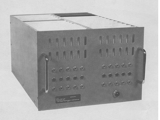 Photo by Kollsman Instrument Corporation
APPLICATIONS
Real time position fixing, navigation, guidance, target location,
trajectory location, weapon aiming, etc. Particularly well suited for
solution of problems in spherical trigonometry as encountered in
astro-guidance and navigation.
Computer was particularly conceived for solving the various
guidance problems associated with Kollsman Star Trackers. As a
navigation computer, it will accept any navigation input and may be
set up to yield any combination of navigation and guidance solutions.
PROGRAMMING AND NUMERICAL SYSTEM
Internal number system Binary
Binary digits/word 24
Binary digits/instruction 23
Arithmetic system Fixed point
Instruction type One address
Number range 223
Instruction word format
+--------------+------------+-------------+
| 8 Bits | 5 Bits | 10 Bits |
+--------------+------------+-------------+
| Control Bits | Address or | Address or |
| | OP Code | OP Code |
+--------------+------------+-------------+
Automatic built-in subroutines Multiply
Registers and B-Boxes
Instruction Register 23 bits
Program Address Register 10 bits
Arithmetic Register A 24 bits
Arithmetic Register R 24 bits
Arithmetic Register D 24 bits
ARITHMETIC UNIT
Incl. Stor. Access Excl. Stor. Access
Microsec Microsec
Add 2.4 57.6
Mult 2.4 752
Div 2.4 2,100
Construction (Arithmetic unit only
Transistors 300
Diodes 900
Arithmetic mode Serial
Timing Synchronous
Operation Sequential
Photo by Kollsman Instrument Corporation
APPLICATIONS
Real time position fixing, navigation, guidance, target location,
trajectory location, weapon aiming, etc. Particularly well suited for
solution of problems in spherical trigonometry as encountered in
astro-guidance and navigation.
Computer was particularly conceived for solving the various
guidance problems associated with Kollsman Star Trackers. As a
navigation computer, it will accept any navigation input and may be
set up to yield any combination of navigation and guidance solutions.
PROGRAMMING AND NUMERICAL SYSTEM
Internal number system Binary
Binary digits/word 24
Binary digits/instruction 23
Arithmetic system Fixed point
Instruction type One address
Number range 223
Instruction word format
+--------------+------------+-------------+
| 8 Bits | 5 Bits | 10 Bits |
+--------------+------------+-------------+
| Control Bits | Address or | Address or |
| | OP Code | OP Code |
+--------------+------------+-------------+
Automatic built-in subroutines Multiply
Registers and B-Boxes
Instruction Register 23 bits
Program Address Register 10 bits
Arithmetic Register A 24 bits
Arithmetic Register R 24 bits
Arithmetic Register D 24 bits
ARITHMETIC UNIT
Incl. Stor. Access Excl. Stor. Access
Microsec Microsec
Add 2.4 57.6
Mult 2.4 752
Div 2.4 2,100
Construction (Arithmetic unit only
Transistors 300
Diodes 900
Arithmetic mode Serial
Timing Synchronous
Operation Sequential
| BRL 1964, AGDIC, starting page 0019
|
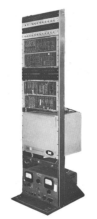 Photo by Kollsman Instrument Corporation
STORAGE
No. of No. of Access
Medium Words Digits Microsec
Ferrite Core
Destructive Readout 32 24 2.4
Ferrite Core
Non-Destructive
Readout 1,024 23 2.4
Non-destructive storage may employ 1, 2, 3, or 4
modules of 256 words each, depending upon system
requirements.
INPUT
Medium Speed
Parallel Binary Data from shaft
encoders, registers and computers. 2.4 microsec
Serial Binary Data 2.4 microsec/
bit
OUTPUT
Medium Speed
Serial Binary 2.4 microsec/bit
Decimal Readout
(Nixie Tube) 50 microsec
Parallel Binary 2.4 microsec
The display is present on a separate output unit
which is not part of the AGDIC proper.
CIRCUIT ELEMENTS OF ENTIRE SYSTEM
Type Quantity
Diodes 2,000 Does not incl. input/output
Transistors 1,000 Does not incl. input/output
Magnetic Cores 768 Destructive readout
Magnetic Cores 23,552 Non-destructive readout
CHECKING FEATURES
Fixed checking features include circuit monitor
lights.
A test program is available as an optional checking
feature.
POWER, SPACE, WEIGHT, AND SITE PREPARATION
Power, computer 0.06 Kw 0.07 KVA 0.86 pf
Volume, computer 0.6 cu ft
Area, computer 0.8 sq ft
Weight, computer 25 lbs
An air conditioner is not required.
PRODUCTION RECORD
Number produced to date 1
Number in current operation 1
Number in current production 0
Number on order 0
Time required for delivery 8 months
RELIABILITY, OPERATING EXPERIENCE
A "worst case" design philosophy was used to insure
reliable operation in ambient temperature from -55oC to
+125oC. Welded connections were made to insure
reliable component interconnections. Plug-in modules
are used to facilitate servicing.
Small, light in weight, and low in power consumption.
Designed for high mobility field use, airborne and
spaceborne applications.
ADDITIONAL FEATURES AND REMARKS
A microminiature version, employing integrated
circuitry, is now under development.
The program storage unit holds the instructions and
constants necessary for the solution of the problem. A
wired core word-select memory array is used for program
storage in order to insure against accidental loss of vital
data in the event of malfunction or misuse.
Arithmetic operations upon the data are performed by
the arithmetic unit. The arithmetic unit employs
transistor shift registers and transistor diode NOR logic
elements.
Photo by Kollsman Instrument Corporation

	STORAGE
			No. of	No. of	Access
 Medium			Words	Digits	Microsec
Ferrite Core
 Destructive Readout	   32	  24	  2.4
Ferrite Core
 Non-Destructive
Readout			1,024	  23	  2.4
 Non-destructive storage may employ 1, 2, 3, or 4
modules of 256 words each, depending upon system
requirements.

	INPUT
 Medium					Speed
Parallel Binary Data from shaft
 encoders, registers and computers.	2.4 microsec
Serial Binary Data			2.4 microsec/
						bit
	OUTPUT
 Medium			Speed
Serial Binary		 2.4 microsec/bit
Decimal Readout
 (Nixie Tube)		50	microsec
Parallel Binary		 2.4 	microsec
 The display is present on a separate output unit
which is not part of the AGDIC proper.

	CIRCUIT ELEMENTS OF ENTIRE SYSTEM
Type 		Quantity
Diodes		2,000 Does not incl. input/output
Transistors	1,000 Does not incl. input/output
Magnetic Cores	768	Destructive readout
Magnetic Cores	23,552	Non-destructive readout

	CHECKING FEATURES
Fixed checking features include circuit monitor
lights.
A test program is available as an optional checking
feature.

	POWER, SPACE, WEIGHT, AND SITE PREPARATION
Power, computer		0.06 Kw 0.07 KVA 0.86 pf
Volume, computer	0.6 cu ft
Area, computer		0.8 sq ft
Weight, computer	25 lbs
An air conditioner is not required.

	PRODUCTION RECORD
Number produced to date		1
Number in current operation	1
Number in current production	0
Number on order			0
Time required for delivery	8 months

	RELIABILITY, OPERATING EXPERIENCE
 A "worst case" design philosophy was used to insure
reliable operation in ambient temperature from -55oC to
+125oC. Welded connections were made to insure
reliable component interconnections. Plug-in modules
are used to facilitate servicing.
	Small, light in weight, and low in power consumption.
Designed for high mobility field use, airborne and
spaceborne applications.

	ADDITIONAL FEATURES AND REMARKS
 A microminiature version, employing integrated
circuitry, is now under development.
 The program storage unit holds the instructions and
constants necessary for the solution of the problem. A
wired core word-select memory array is used for program
storage in order to insure against accidental loss of vital
data in the event of malfunction or misuse.
 Arithmetic operations upon the data are performed by
the arithmetic unit. The arithmetic unit employs
transistor shift registers and transistor diode NOR logic
elements.
| BRL 1964, A M 943, starting page 0020
|
A M 943
Addressograph-Multigraph 943
MANUFACTURER
Addressograph-Multigraph Corporation
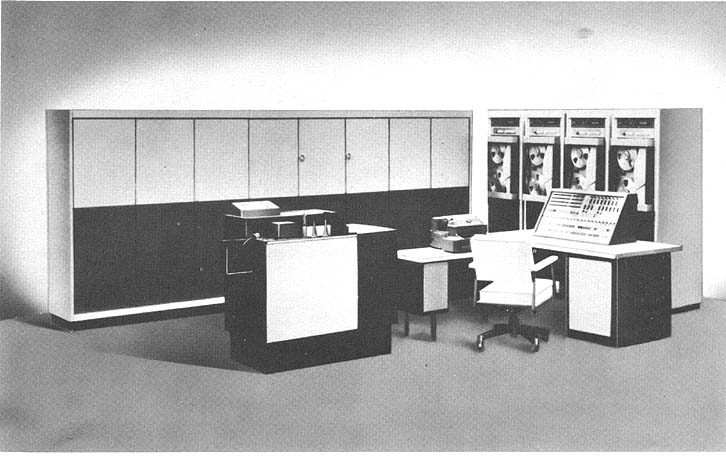 Photo by the Addressograph-Multigraph Corporation
APPLICATIONS
A general purpose computing system employing a unique
externally programmed technique. Each system is tailored to the
users need utilizing standard modular components.
PROGRAMMING AND NUMERICAL SYSTEM
Internal number system Binary coded dec.
Decimal digits/word Variable
Instructions.per word.
There are no instructions.The data in the memory
is scanned and computed.
Arithmetic system Fixed point
Automatic built-in subroutines include sort, auto-
matic data coordinating routines.
Automatic coding techniques, registers and B-boxes
are not necessary.
ARITHMETIC UNIT
Incl. Stor. Access Excl. Stor. Access
Microsec Microsec
Add 22 12
Mult 59 49
Div 59 49
The above times are per character.
Arithmetic mode Serial
Timing Synchronous
Operation Sequential
STORAGE
Magnetic Tape
No. of units that can be connected 16 Units
No. of chars/linear inch 556 Chars/inch
Channels or tracks on the tape 7 Track/tape
Blank tape separating each record 0.75 Inches
Tape speed 75 Inches/sec
Transfer rate 41,700 Chars/sec
Start time 5.1 Millisec
Stop time 5.1 Millisec
Average time for experienced
operator to change reel of tape 45 Seconds
Physical properties of tape
Width 0.5 Inches
Length of reel 2,450 - 2,500 Feet
Composition HD Mylar
INPUT
Medium Speed
Magnetic Tape (947) 41,700 chars/sec
Card Reader (941) 760 cards/sec
Paper Tape (948) 1,000 chars/sec
OUTPUT
Medium Speed
Magnetic Tape (947) 41,700 chars/sec
Photo by the Addressograph-Multigraph Corporation
APPLICATIONS
A general purpose computing system employing a unique
externally programmed technique. Each system is tailored to the
users need utilizing standard modular components.
PROGRAMMING AND NUMERICAL SYSTEM
Internal number system Binary coded dec.
Decimal digits/word Variable
Instructions.per word.
There are no instructions.The data in the memory
is scanned and computed.
Arithmetic system Fixed point
Automatic built-in subroutines include sort, auto-
matic data coordinating routines.
Automatic coding techniques, registers and B-boxes
are not necessary.
ARITHMETIC UNIT
Incl. Stor. Access Excl. Stor. Access
Microsec Microsec
Add 22 12
Mult 59 49
Div 59 49
The above times are per character.
Arithmetic mode Serial
Timing Synchronous
Operation Sequential
STORAGE
Magnetic Tape
No. of units that can be connected 16 Units
No. of chars/linear inch 556 Chars/inch
Channels or tracks on the tape 7 Track/tape
Blank tape separating each record 0.75 Inches
Tape speed 75 Inches/sec
Transfer rate 41,700 Chars/sec
Start time 5.1 Millisec
Stop time 5.1 Millisec
Average time for experienced
operator to change reel of tape 45 Seconds
Physical properties of tape
Width 0.5 Inches
Length of reel 2,450 - 2,500 Feet
Composition HD Mylar
INPUT
Medium Speed
Magnetic Tape (947) 41,700 chars/sec
Card Reader (941) 760 cards/sec
Paper Tape (948) 1,000 chars/sec
OUTPUT
Medium Speed
Magnetic Tape (947) 41,700 chars/sec
| BRL 1964, A M 943, starting page 0021
|
Paper Tape (948) 240 cards/sec
A complete range of off-line label and line printer
systems are available.
CIRCUIT ELEMENTS OF ENTIRE SYSTEM
Type Quantity
Tubes 0
Diodes 45,000
Transistors 15,000
Magnetic Cores 1,024 (double bucket
The cores are for a 1,024 Input/output memory
associated with Input/Output devices. Modular
construction is used. Each system employs only the
necessary logic for each particular application. The
number of circuit elements is dependent on the machine
size.
CHECKING FEATURES
Checking features include an automatic read-after-
write, record size verification for both variable and fixed
length records, redundant arithmetic operations, and
horizontal and vertical parity check.
POWER, SPACE, WEIGHT, AND SITE PREPARATION
Power, computer 11.2 KVA
Volume, computer 258 cu ft
Area, computer 43 sq ft
Floor loading 70 lbs/sq ft
Weight, computer 3,000 lbs
False flooring is recommended. Air conditioning is
required for operational comfort. Requirements vary
with the system size.
PRODUCTION RECORD
Number produced to date 5
Number in current operation 5
Number in current production 1
Anticipated production rates l/month
Time required for delivery 6 to 9 months
COST, PRICE AND RENTAL RATES
Monthly
Model System/Component Purchase Lease
943 File Processor $300,000 $7,000
946 Tape Units 16,950 470
947 Tape Units 18,970 540
941 Card Reader 31,000 500
Off-line label printers
Line printers
Punched paper tape
On-line printing
Maintenance is provided on rental equipment.
Maintenance contracts are available for purchased
equipment.
PERSONNEL REQUIREMENTS
One 8-hour Two 8-Hour Three 8-Hour
Shift Shifts Shifts
Supervisors 1
Programmers 2
Librarians 1 2 3
Operators 1 2 3
Technicians 2 3 4
In-Output Oper 2 4 6
Tape Handlers 1 2 3
Customer and prospect classes are held regularly,
either on-site or at local Addressograph-Multigraph
offices.
Installation and systems assistance is provided by
the A-M Corporation.
ADDITIONAL FEATURES AND REMARKS
Outstanding features include high speed sorting,
high processing speeds, efficient utilization of memory,
modular construction, business-oriented logic,
simplified programming, quick program change
modification, and reduced programming costs.
The simplified patchboard reduces programmer
training time, and reduces the number of programers
required and instruction storage is eliminated.
The individual storage units are independently
controlled, hence are capable of reading while writing.
Each storage unit is buffered 100%, hence the system is
capable of reading while writing while computing. The
result is that 99,% of the applications are performed at the
speed-of-tape rates.
The system is programmed in Boolean logic by means
of a plugboard the result is ease and speed in learning
programming, ease and speed in programming,
debugging, and in modifying existing programs.
The A-M 943 features include automatic memory
loading, reread, read-after-write, blocking and block
counting on input and output, directly addressable data,
automatic input/output channel control, automatic data
source switching and control and directly addressable
output media.
* Double bucket implies a two section memory, each
section with storage capacity for 1,024 characters.
Provides complete buffering overlap, i.e., while
processing data from one section of memory, the other
section can be loaded.
| BRL 1964, A M 960, starting page 0022
|
A M 960
Addressograph-Multigraph Printer Processor 960
MANUFACTURER
Addressograph-Multigraph Corporation
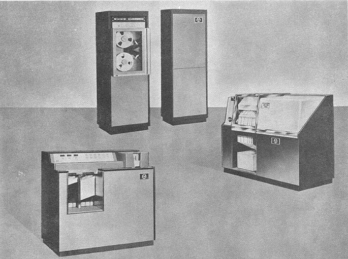 Photo by the Addressograph-Multigraph Corp.
APPLICATIONS
The system performs off-line printing at 1,000 lines per minute,
accepts magnetic tape input from a variety of computers and is
universally adaptable to commercial and scientific printing
applications. The command repertoire is designed to facilitate
editing of raw data. The printer-buffer, a standard feature, permits
compute-print overlap.
PROGRAMMING AND NUMERICAL SYSTEM
Internal number system Binary coded dec.
Binary digits/word Variable
Binary digits/instruction 8 (Average)
Instructions/word Char. oriented system
Instructions decoded 28
Arithmetic system Fixed point
Instruction type 1, 2, 3 address
+-------+-----------+-----------+----+-----------+
| X | XXX | XXX | X | XXX |
+-------+-----------+-----------+----+-----------+
| OP | A Address | B Address | OM | C Address |
+-------+-----------+-----------+----+-----------+
All functions are programmed. Assembly programs are available
to function on the A-M 960 PrinterProcessor or the prime
computer in the installation.
A modify address instruction is a standard feature.
The C Address of an instruction is used only in the case of
unconditional branches. The Operation Modifier is in conjunction
with 9 of the 28 instructions.
ARITHMETIC UNIT
Incl. Stor. Access Excl. Stor. Access
Microsec Microsec
Add 200 130
Mult 18,425 17,500
Div 24,950 23,000
The figures are for five digit operands.
Multiply and Divide are programmed.
Arithmetic mode Serial
Timing Asynchronous
Operation Sequential
Photo by the Addressograph-Multigraph Corp.
APPLICATIONS
The system performs off-line printing at 1,000 lines per minute,
accepts magnetic tape input from a variety of computers and is
universally adaptable to commercial and scientific printing
applications. The command repertoire is designed to facilitate
editing of raw data. The printer-buffer, a standard feature, permits
compute-print overlap.
PROGRAMMING AND NUMERICAL SYSTEM
Internal number system Binary coded dec.
Binary digits/word Variable
Binary digits/instruction 8 (Average)
Instructions/word Char. oriented system
Instructions decoded 28
Arithmetic system Fixed point
Instruction type 1, 2, 3 address
+-------+-----------+-----------+----+-----------+
| X | XXX | XXX | X | XXX |
+-------+-----------+-----------+----+-----------+
| OP | A Address | B Address | OM | C Address |
+-------+-----------+-----------+----+-----------+
All functions are programmed. Assembly programs are available
to function on the A-M 960 PrinterProcessor or the prime
computer in the installation.
A modify address instruction is a standard feature.
The C Address of an instruction is used only in the case of
unconditional branches. The Operation Modifier is in conjunction
with 9 of the 28 instructions.
ARITHMETIC UNIT
Incl. Stor. Access Excl. Stor. Access
Microsec Microsec
Add 200 130
Mult 18,425 17,500
Div 24,950 23,000
The figures are for five digit operands.
Multiply and Divide are programmed.
Arithmetic mode Serial
Timing Asynchronous
Operation Sequential
| BRL 1964, A M 960, starting page 0023
|
	STORAGE
				No. of		Access
Medium				Characters 	Microsec
Magnetic Cores (Main)		4,000		10
Magnetic Cores (Printer-Buffer)   133		10
Magnetic Tape
No. of units that can be connected	    10 Units
No. of chars/linear inch		   556 Chars/inch
Channels or tracks on the tape		     7 Track/tape
Blank tape separating each record	     0.75 Inches
 Tape speed				    75 Inches/sec
 Transfer rate				41,667	Chars/sec
 Start time				     5	Millisec
 Stop time				     5	Millisec
 Average time for experienced
operator to change reel of tape		    45	Seconds
 Physical properties of tape
  Width					    0.5	Inches
  Length of reel			2,400	 Feet
  Composition				Mylar

	INPUT
Medium			Speed 		Remarks
Magnetic Tape 947 	41,000 chars/sec Read after Write
Magnetic Tape 944 	41,000 chars/sec Read Only
Card Reader 941		   750 cards/min Double Read Head
Paper Tape 948		   500 chars/sec 5,6,7, & 8 Channel
	Other magnetic tape units that are adaptable are the IBM
729, Models II, IV, V, and VI.

	OUTPUT
	Medium			Speed
Printer 961		 1,000 lines/min (Incl. Buffer)
Magnetic Tape 947 	41,000 chars/sec(Incl. Read after Write)
Paper Tape 948	107 or	(5,6,7, & 8
			   240 chars/sec		Channel)
Card Punch 949		   200 cards/min
	Input and output devices can be connected to the system in
any configuration, if the total number of components does not
exceed ten.

	CIRCUIT ELEMENTS OF ENTIRE SYSTEM
Type	Quantity
Tubes	  	    0
Diodes		5,750
Transistors	5,188
Magnetic Cores	4,000 (Characters)

	CHECKING FEATURES
Parity checking and read-after-write checking, as required,
is performed.

	POWER, SPACE, WEIGHT, AND SITE PREPARATION
Volume, computer		118.55 cu ft
Area, computer	25.6		sq ft
Floor loading	106		lbs/sq ft
Weight, computer	1,200		lbs
Weight, printer	1,515 		lbs
 False flooring is recommended. Air conditioning is required
for the operator's comfort only.

PRODUCTION RECORD
Number produced to date		4
Number in current operation	2
Number in current production	4
Number on order			4

Anticipated production rates	25/quarter
Time required for delivery 	6 months

COST, PRICE AND RENTAL RATES
				Monthly
Model	System/Component	Purchase	Lease
960	Printer-Processor	115,000		2,950
944	Tape Unit		11,500		  325
947	Tape Unit		18,970		  540
941	Card Reader		31,000		  500
 Maintenance provided on rental equipment. Maintenance
contracts available on purchased equipment.

PERSONNEL REQUIREMENTS
Programmers
 Dependent upon programming requirements.
Coders
 Dependent upon programming requirements.
 Training made available by the manufacturer to the user
includes customer and prospect classes which are held regularly
either on-site or at a local A-M branch office.
 Installation and systems assistance is supplied by the
manufacturer.

ADDITIONAL FEATURES AND REMARKS
 The instruction format is similar to other widely used
satellite printing systems; there is a set of powerful editing
instructions, and the data and instructions are character
oriented.
 The print buffer is standard and the system can accept
data from A-M or IBM peripheral devices.
 The system is equipped with a 4,000 character internal memory.
Each character is represented by 8 bite or binary digits; 6 data
bits, 1 parity bit, and an 8th bit which marks the Index Point
or End of the Field. Each of the 4,000 character positions is
individually addressable. Each memory location has a 3 character
"address." The units and tens characters of this address are
always numeric and together span 100 positions. The third and
most significant character can be any of forty characters so
that the full 4,000 positions can be uniquely addressed. The
forty characters are those whose numeric bits (8 4 2 1) have the
same values 0 through 9 for each of the four possible zone bit
combinations (A and B, A no B, B no A, and no A and B bits).
 Signs are carried as zone bits over the unit's digits of
numeric fields. All negative fields (or words) contain a B bit
over their unit's digit. All positive numbers contain either no
A and no B, an A and no B, or an A and B bit.
	The printer-processor is variable word length machine. This
permits the number of characters in a word to be any length from
one character upward. It allows word: to be compressed in a
length by not storing non-si4-n ificant characters, which
improves the storage efficiency of the memory. Second, it
permits processing, with equal efficiency, data from any
computing system having a basic 6 bit character regardless of
the computer's word length. It enables the programmer to write
routines and programs with one instruction per operation--
irrespective of the length of the data fields.
	Since the printer-processor is a character-oriented processor
rather than a word-oriented processor, addressing is done
character by character. The address portions of each instruction
specify either the high order or low order characters of the
words to be operated upon by that instruction.
| BRL 1964, AN/MSM 42, starting page 0024
|
AN/MSM 42
Fault Locator Computer
MANUFACTURER
Sperry Gyroscope Company
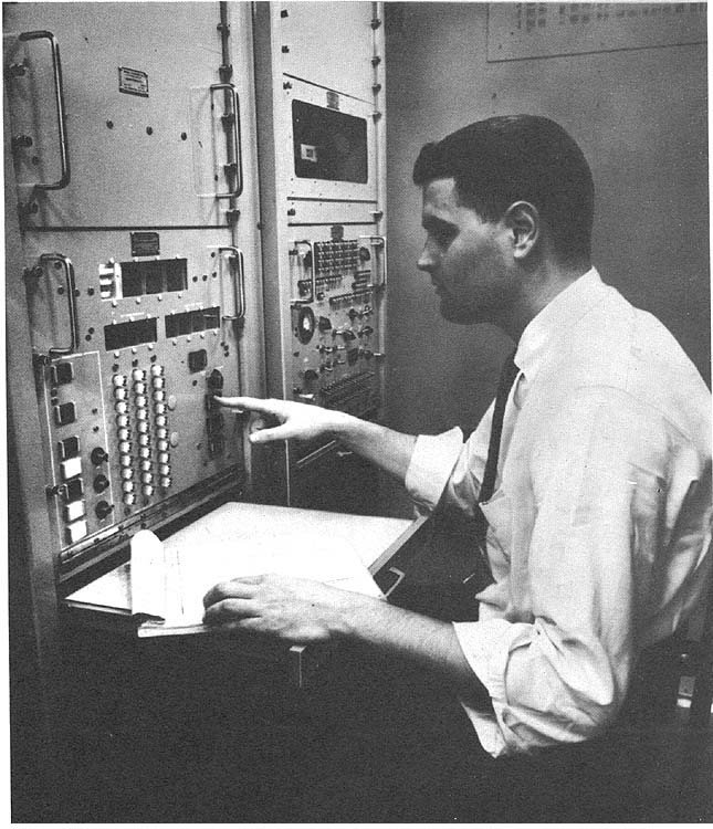 Photo by Special Products Group, Sperry Gyroscope Co.
APPLICATIONS
A general purpose computer, designed especially to control
automatic test equipment. It operates online and in real-time
applications. It is designed for use by military personnel in
the field, and is applicable to production test situations in
which it can control tests, evaluate data, perform statistical
analysis and provide output information, printed on punched tape
or as control signals for automatic process control.
PROGRAMMING AND NUMERICAL SYSTEM
Internal number system Binary
Binary digits/word 56
Binary digits/instruction 28
Instructions/word 2
Instructions decoded 256
Arithmetic system Fixed point
Two's complement, fractional number, arithmetic is used.
Instruction type One address
Number range -(1 - 2-56) to + (1 - 2-56)
Photo by Special Products Group, Sperry Gyroscope Co.
APPLICATIONS
A general purpose computer, designed especially to control
automatic test equipment. It operates online and in real-time
applications. It is designed for use by military personnel in
the field, and is applicable to production test situations in
which it can control tests, evaluate data, perform statistical
analysis and provide output information, printed on punched tape
or as control signals for automatic process control.
PROGRAMMING AND NUMERICAL SYSTEM
Internal number system Binary
Binary digits/word 56
Binary digits/instruction 28
Instructions/word 2
Instructions decoded 256
Arithmetic system Fixed point
Two's complement, fractional number, arithmetic is used.
Instruction type One address
Number range -(1 - 2-56) to + (1 - 2-56)
| BRL 1964, AN/MSM 42, starting page 0025
|
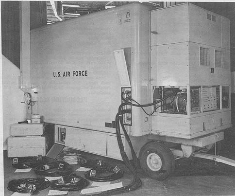 Photo by Special Products Group, Sperry Gyroscope Co.
Instruction word format
+-------------+--------+-------+---------+---------+
| 1 12 | 13 | 14 | 15 20 | 21 28 |
+-------------+--------+-------+---------+---------+
| Instruction | Parity | Spare | Channel | Sector |
| | | | Address | Address |
+-------------+--------+-------+---------+---------+
Automatic built-in subroutines
Time interval generator using arithmetic unit. Registers and B-Boxes
Two insturction-counter registers, selectable and addressable by branch
instructions, provide one level of fully
automatic subroutine control within a main routine.
Automatic coding is being developed to accept test language input and
produce minimum access time coding. A subroutine library contains
subroutines for updating addresses, performing test operations on
a, prime system, self test functions, printing out test results,
etc. Service routines are available for memory loading, unloading and
checking, correcting instruction word parity, setting up switching and
reference data for aided manual or semi-automatic tests and memory
searching for specific data or memory reference.
ARITHMETIC UNIT
Incl. Stor. Access Excl. Stor. Access
Microsec Microsec
Add 4,000 57
Multiply and Divide
Require 28 word times using 28 bit operands.
Construction (Arithmetic unit only)
Transistors, 2 magnetostriction delay line registers and dynamic flip-flops.
Arithmetic mode Serial
Timing Synchronous
Operation Sequential
Internal operation is synchronous. External interface provisions are
asynchronous. Internal operations are primarily sequential.
Input/output equipment will operate concurrently.
Square-root can be easily provided in hardware if required. A special
instruction called Repeat-Add causes an add-cycle to reoccur each
word time until the sign of accumulator changes.
This operation is concurrent with other computer operations.
It it used for time interval generation.
STORAGE
No. of No. of Access
Medium Words Digits Microsec
Magnetic Drum 16,384 106 bits 8,000 (max)
One-word Registers 16 16 x 56 bits 57
Punched. Paper Tape 30 chars/sec
Photo by Special Products Group, Sperry Gyroscope Co.
Instruction word format
+-------------+--------+-------+---------+---------+
| 1        12 |    13  |   14  | 15   20 | 21   28 |
+-------------+--------+-------+---------+---------+
| Instruction | Parity | Spare | Channel | Sector  |
|             |        |       | Address | Address |
+-------------+--------+-------+---------+---------+
Automatic built-in subroutines
Time interval generator using arithmetic unit. Registers and B-Boxes
Two insturction-counter registers, selectable and addressable by branch
instructions, provide one level of fully
automatic subroutine control within a main routine.

Automatic coding is being developed to accept test language input and
produce minimum access time coding. A subroutine library contains
subroutines for updating addresses, performing test operations on
 a, prime system, self test functions, printing out test results,
 etc. Service routines are available for memory loading, unloading and
checking, correcting instruction word parity, setting up switching and
reference data for aided manual or semi-automatic tests and memory
searching for specific data or memory reference.

ARITHMETIC UNIT
          Incl. Stor. Access     Excl. Stor. Access
          Microsec               Microsec
Add           4,000                  57
Multiply and Divide
Require 28 word times using 28 bit operands.
Construction (Arithmetic unit only)
Transistors, 2 magnetostriction delay line registers and dynamic flip-flops.
Arithmetic mode           Serial
Timing                    Synchronous
Operation                 Sequential
Internal operation is synchronous. External interface provisions are
asynchronous. Internal operations are primarily sequential.
Input/output equipment will operate concurrently.

Square-root can be easily provided in hardware if required. A special
instruction called Repeat-Add causes an add-cycle to reoccur each
word time until the sign of accumulator changes.
This operation is concurrent with other computer operations.
It it used for time interval generation.

STORAGE
                   No. of    No. of      Access
 Medium            Words     Digits      Microsec
 Magnetic Drum   16,384      106 bits    8,000 (max)
One-word Registers    16     16 x 56 bits  57
Punched. Paper Tape 30 chars/sec
| BRL 1964, AN/MSM 42, starting page 0026
|
Existing model has no provision for magnetic tape. The next model now in
design will have it.
An alternative drum is available in the same package size having 32,000
words of storage with an access time of 16,000 microsecond (max).

INPUT
 Medium                Speed
 Paper Tape            30 chars/sec
 Includes parity checking on each 7 bit character.
Typewriter             Manual
IBM standard electric typewriter with Soroban encoder.

Keyboard (3 col. dec.) Manual
 Select 1 of 1,000 stored routines
Remote Panel           Manual
Serial, parallel, and series-parallel digital data inputs are provided.
Analog inputs to A-D conversion or limit comparison are included.

OUTPUT
 Medium                Speed
 Typewriter            10 chars/sec
IBM standard electric typewriter with Soroban decoder. Illuminated Displays
English message and alpha-numeric programmable displays.
Remote Panel           Manual
56 bit parallel output data link provided. Two D-A converters with f 100
volt range +- 0.01% accuracy provided.

The Remote Technician's Panel is designed to provide communication between
a remote operator, e.g. on a prime system under test, and the computer.
 A three digit decimal display together with a small handbook allows the
computer to instruct the remote technician to do specific jobs or ask him
questions answerable yes or no. Two buttons are provided by which the
technician can answer questions and signal compliance with instructions. The
handbook provides translations from the 3 digit number to English language
statements and is, of course, compiled for the particular application.
The computer operator does not have any part in this operation.

CIRCUIT ELEMENTS OF ENTIRE SYSTEM
Type              Quantity
Tubes                 26
Diodes            13,600
Transistors        3,700
All the tubes are in D-A converter for which transistorized circuitry can
be used.

CHECKING FEATURES
Manual controls on maintenance panel allow complete checking of individual
functions throughout computer.
Instructions are parity checked prior to execution. Input/output is parity
checked. Checking features can be programmed as required. A comprehensive
self-check and fault location routine is provided.

POWER, SPACE, WEIGHT, AND SITE PREPARATION
Power, computer        1.3 AC Kw      0.1 DC Kw
 For ambient 0o 50o C for operator comfort only.
Volume, computer       8.2 cu ft
Area, computer        14.8 sq ft
Room size              6 x 8 ft
Floor loading          200 lbs/sq ft
                       150 lbs concen max
Weight, computer       900 lbs
Computer can be provided for either 208 volt 4-wire y 400 volt AC plus 28
volt DC or, 208 volt, 60 cycles 4-wire y or, 115/220 volt, 60 cycle single phase.
Size and weight based on access to front only of each rack. 30°% reduction
in size and weight can be obtained if access is provided to front and rear of cabinets.

PRODUCTION RECORD
Number produced to date 1
Number in current operation 1
Time required for delivery 9 months

PERSONNEL REQUIREMENTS
              One 8-Hour Two 8 Hour Three 8-Hour
              Shift      Shifts     Shifts
Technicians      1          2          3
Programming and maintenance training available in Sperry training school.
Above personnel requirement is based on existing application to automatic
checkout system for which programming has been finished. In this
application the technician operates the computer.

RELIABILITY, OPERATING EXPERIENCE
Standard logic modules having extensive usage are employed. All components
derated for both voltage and power dissipation. Careful workmanship in
assembly and wiring contributes to reliability.
Over 5,000 hours to date on initial model shows mean time between failures
(MTFB) exceeding 200 hours.
Planned improvements in the production models are expected to raise this to
1,000 hours.
Computer will meet requirements of MIL-T-21200 and MIL-I-26600.

ADDITIONAL FEATURES AND REMARKS
Equipment specially designed for use in automatic confidence and diagnostic
testing from systems down to piece part level. Applicable to field, depot,
factory, environmental test laboratories.
Large memory and logical capabilities allow test and fault isolation with
few test points compared to conventional equipment. High computer speed
allows many peripheral calculations to be carried on without slowing test
processing.
The AN/MSM-42 includes extensive signal and control switching capabilities
with 10 x 20 x 6 crossbar switch and additional relays. 56-bit parallel
register controls switching functions.
Portable signal pickup unit contains crossbar switch, signal processing
circuits and emitter followers for signal pickup close to signal source.
Remote switching allows use of fewer wires in long cables to computer.
| BRL 1964, AN/MSM 42, starting page 0027
|
FUTURE PLANS
Next model will provide magnetic tape, higher speed punched tape equipment.
New logical elements will provide increase in reliability to an expected
1,000 hours mean time between failures.
Additional input/output channels will be provided to allow for addition
of disk files or other external equipment. Input/output control will allow con-
current input/output and processing. Provisions will be made to incorporate
fast access memory system for those applications requiring faster
access than drum.
D-A Converter will be changed to solid state.
| BRL 1964, APOLLO DC, starting page 0028
|
APOLLO DC
Apollo Digital Computer

MANUFACTURER
Information Systems Division Raytheon Manufacturing Company

APPLICATIONS
Lunar vehicle guidance.
The Apollo computer is a general purpose digital computer, specially
organized for handling moon flight data.

PROGRAMMING AND NUMERICAL SYSTEM
Internal number system          Binary
Binary digits/word              15 + Parity
Automatic coding
Programmed double and triple precision operations.

ARITHMETIC UNIT
Incl. Stor. Access
             Microsec
Add            23.4
 Double-precision multiply via subroutine is 780
microseconds.
Arithmetic mode Parallel

 STORAGE
                                            Access
 Medium                                     Microsec
Magnetic Core-Rope Fixed data and programs   11.7
                                            (Cycle)
Magnetic Core              Variables
 (Erasable)
Coincident-current type of magnetic storage.

INPUT
 Medium Speed Remarks
Keyboard Manual (16 Keys)

OUTPUT
 Medium                Remarks
 Character Display     (21 Digits)
The five small coupling and display units (CDUs) will be identical and
interchangeable electrical shaft encoder units for fine precision angle resolution.
Each CDU will consist of three wheel dials, a manual thumbwheel switch, and
associated electronics. They will read out angle information to the navigator
and the computer will be a junction through which the navigator will be
able to command new desired angles.

CIRCUIT ELEMENTS OF ENTIRE SYSTEM
Type            Quantity         Remarks
Tubes              0
Diodes                            Silicon
Transistors                       Silicon
Core rope memory and integrated circuitry are built up in plug-in
replaceable module form. Each module contains a different portion of the
computer (memory, programs, etc.). Each plugs into an assigned position
in one of two drawer-like trays. By carrying spares, astronauts will be
able to make in-flight repairs if needed by plugging in new
modules. A junction box at the rear of the computer trays connects the
computer to the rest of the guidance and navigation system.
Magnesium heat sink is used for the power servo assembly in the Apollo
command module navigation and guidance system. Following assembly of all
the components, the connections are welded and the entire module is
encapsulated in a polyurethane foam.

CHECKING FEATURES
Parity checking is used.

RELIABILITY, OPERATING EXPERIENCE
The power servo assembly, like the computer, will be built up from
in-flight replaceable modules mounted on a tray and connecting into
the guidance and navigation system through the tray junction box.
Electrical power from the spacecraft's main supply will feed through the
servo assembly where it will be converted into various alternate and
direct currents of the different frequencies required.

ADDITIONAL FEATURES AND REMARKS
The Apollo guidance and navigation system will be self-contained on board
the spacecraft and will be capable of operation without information or
instructions from earth. The system will also be capable of accepting ground
information and commands.
Guidance and navigation will consist of three main subsystems. These
include: an inertial measurement unit, optical unit, and computer unit,
plus displays and controls. Also present will be: a power servo assembly;
a map and data viewer; and five coupling and display units.
The inertial measurement unit will consist of an inner member stable
platform isolated from spacecraft attitude motion through suspension
within a three degree-of-freedom spherical gimbal system with associated
inter-gimbal assemblies (slip rings, bearings, servo torque motors and
electromagnetic angle resolvers).
The inner member will consist of three 2 1/2-inch diameter inertial
reference integrating gyroscopes and three 1.6-inch diameter pulsed
integrating pendulum accelerometers.
Four industrial firms are fabricating systems that will be used on the
Apollo spacecraft These are:
   AC Spark Plug Div., General Motors Corp., Wisconsin and Massachusetts.-
     -inertial measurement unit and associated displays and controls;
     inertial measurement gyroscopes; integration of the total system and its
     displays and controls; and ground support equipment.

   Kollsman Instrument Corp., N.Y.---Optical subsystem, map and data viewer,
     and associated ground support equipment.

   Raytheon Company's Space and Information Systems Division, Massachusetts, -
      -digital computer and associated displays.

   Sperry Gyroscope Company, N.Y.---pulsed integrating pendulums used in the
     inertial measurement unit accelerometers.
For the sake of a complete survey, permission was granted to extract this
information from the 25 Oct 63
ELECTRONIC DESIGN just as this report was sent to the printer. Lack of time
prohibited contacting the Instrumentation Laboratory of the MIT.
| BRL 1964, APOLLO DC, starting page 0029
|
| BRL 1964, ASI 210, starting page 0030
|
ASI 210
MANUFACTURER
Advanced Scientific Instruments, Inc.
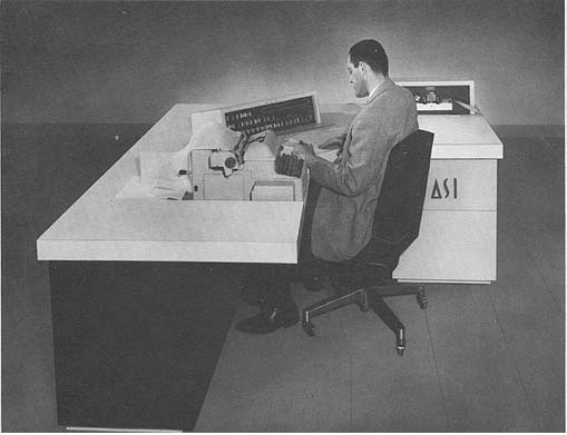 Photo by Advanced Scientific Instruments, Inc.
APPLICATIONS
Scientific and Engineering Computation
Data Processing
On-Line Process Control
Off-Line Control and Satellite Operation with other computers.
Real-Time Control of all types of systems.
PROGRAMMING AND NUMERICAL SYSTEM
Internal number system Binary
Binary digits/word 21
Binary digits/instruction 21
Instructions/word 1
Instructions decoded 37
Arithmetic system Fixed point
Instruction type One address
Number range - to + using floating point
Routine - (1 - 2-20) to + (1 - 2-20)
Instruction word format
+------+-----------+----------+-----------+
| 1 5 | 6 | 7 8 | 9 21 |
+------+-----------+----------+-----------+
| OP | Indirect | Index | Operand |
| Code | Address | Address | Address |
+------+-----------+----------+-----------+
Registers and B-Boxes
Assembly Register 21 bits
Address Register 13 bits
Limit Address Register 13 bits
Accumulator 21 bits
Accumulator Extension 21 bits
3 Index Registers
ARITHMETIC UNIT
Incl. Stor. Access Excl. Stor. Access
Microsec Microsec
Add 6 2
Mult 50 46
Div 62 56
Photo by Advanced Scientific Instruments, Inc.
APPLICATIONS
Scientific and Engineering Computation
Data Processing
On-Line Process Control
Off-Line Control and Satellite Operation with other computers.
Real-Time Control of all types of systems.
PROGRAMMING AND NUMERICAL SYSTEM
Internal number system Binary
Binary digits/word 21
Binary digits/instruction 21
Instructions/word 1
Instructions decoded 37
Arithmetic system Fixed point
Instruction type One address
Number range - to + using floating point
Routine - (1 - 2-20) to + (1 - 2-20)
Instruction word format
+------+-----------+----------+-----------+
| 1 5 | 6 | 7 8 | 9 21 |
+------+-----------+----------+-----------+
| OP | Indirect | Index | Operand |
| Code | Address | Address | Address |
+------+-----------+----------+-----------+
Registers and B-Boxes
Assembly Register 21 bits
Address Register 13 bits
Limit Address Register 13 bits
Accumulator 21 bits
Accumulator Extension 21 bits
3 Index Registers
ARITHMETIC UNIT
Incl. Stor. Access Excl. Stor. Access
Microsec Microsec
Add 6 2
Mult 50 46
Div 62 56
| BRL 1964, ASI 210, starting page 0031
|
Construction (Arithmetic Unit Only)
 Transistors          3,000
 Condenser-Diodes    28,352
 Magnetic-Cores      86,000
 Delay lines, inductors, and transformers.
Arithmetic mode       Parallel
Timing                Synchronous
Operation             Concurrent

STORAGE
                                     Access
 Medium            No. of Words      Microsec
 Magnetic Core     4,096 or 8,192       1
 Magnetic Tape
No. of units that can be connected     32 Units
No. of chars/linear inch              200 or 556 Chars/inch
Channels or tracks on the tape          7 Track/tape
Blank tape separating each record       0.88 Inches
Tape speed                            112.5 Inches/sec
Transfer rate                      22,500/62,500 Chars/sec
Start time                              2.5 Millisec
Stop time                               1.0 Millisec
Physical properties of tape
 Width                                  0.5 Inches
 Length of reel                     2,400 Feet
 Composition                         Mylar

INPUT
Medium                    Speed
Paper Tape                 500 chars/sec
Typewriter                 Manual
Magnetic Tape              112.5 inches/sec
Cards                      100 or 800 cards/min

OUTPUT
Medium Speed
Paper Tape                 110 chars/sec
Typewriter                  10 chars/sec
Magnetic Tape               15 inches/sec
Cards                      100 or 250 cards/min
Line Printer             1,000 lines/min
(48 FORTRAN character set) 200 lines/min
Input/output can be to any of all commonly used devices.

CIRCUIT ELEMENTS OF ENTIRE SYSTEM
Type          Quantity
Tubes                  0
Diodes            28,352
Transistors        3,006
Magnetic Cores    86,000

CHECKING FEATURES
Overflow detection and branching for add, subtract, and divide.
Automatic "Fail" interrupt for appropriate peripheral equipment.

POWER, SPACE, WEIGHT, AND SITE PREPARATION
Power, computer       1.7 Kw 1.9 KVA
Volume, computer     73 cu ft
Area, computer       35 sq ft
Weight, computer    975 lbs
No special site preparation except for wall electrical receptacle.
No air conditioner required.

PRODUCTION RECORD
Number produced to date      12
Number in current operation  12

COST, PRICE AND RENTAL RATES
MODEL DESCRIPTION PURCHASE
ASI-210 4,096 word storage system    $ 94,000
ASI-210 8,192 word storage system     116,800
A-11 Tape Unit                         33,000
A-12 Tape Unit                         41,400
A-30 Typewriter                         9,880
A-40 Punch Card Buffer                 19,600
A-60 Line Printer                      25,400
A-120 Line Printer                     98,000

PERSONNEL REQUIREMENTS
              One 8-Hour   Two 8-Hour   Three 8-Hour
              Shift        Shifts       Shifts
Supervisors     1            1            1
Analysts        2            2            2
Programmers     2            2            2
Coders          4            4            4
Clerks          1            2            3
Operators       1            2            3
In-Output Oper  1            2            3
The manufacturer will provide free operator and programmer training.

RELIABILITY, OPERATING EXPERIENCE
The circuits are designed and built to operate under "worst case"
conditions.

ADDITIONAL FEATURES AND REMARKS
No air conditioning required. Trapped program interrupt. Three index
 registers. In/Out data transfer simultaneous with computation.
A true multiply and true divide. Unique design method of
 handling input/output equipment communication.
| BRL 1964, ASI 420, starting page 0032
|
ASI 420
MANUFACTURER
Advanced Scientific Instruments, Inc.
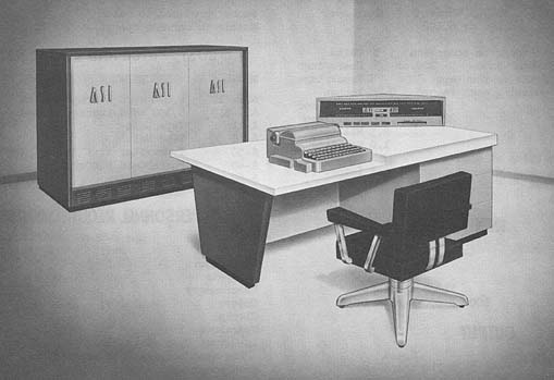 Photo by Advanced Scientific Instruments, Inc.
APPLICATIONS
Scientific and engineering computation.
Large scale data processing and analysis.
On-line process control.
Real-time control of all types of systems.
PROGRAMMING AND NUMERICAL SYSTEM
Internal number system Binary
Binary digits/word 42
Binary digits/instruction 42
Instructions/word 1
Instructions decoded 60
Arithmetic system Fixed and floating point
Instruction type One address
Number range - (1 - 2-40) to (1 - 2-40)
Instruction word format
+------+-------+--------+--------+---------+--------+-------+-------+
| 1 5 | 6 | 7 | 8 | 9 | 10 12 | 13 27 |28 42 |
+------+-------+--------+--------+---------+--------+-------+-------+
| OP | Indi- | Repeat | Break- | Class | Unused | Index | Oper- |
| Code | rect | Bit | Point | Desig- | Bits | Addr. | and |
| | Addr. | | | | | | |
+------+-------+--------+--------+---------+--------+-------+-------+
Registers and B-Boxes
Assembly Register 42 bits
Address Register 15 bits
Limit Address Register 15 bits
Accumulator 42 bits
Index Registers
Number limited only by size of memory.
ARITHMETIC UNIT
Incl. Stor. Access Excl. Stor. Access
Microsec Microsec
Add 6 2
Mult 60 56
Div 96 90
Construction (Arithmetic unit only)
Vacuum-Tubes 0
Transistors 5,410
Condenser-Diodes 50,400
Magnetic-Cores 344,064
Other - delay lines, inductors, transformers
Arithmetic mode Parallel
Timing Synchronous
Operation Concurrent
STORAGE
Access
Medium No. of Words Microsec
Magnetic Core 8,182 to 32,768 1
Photo by Advanced Scientific Instruments, Inc.
APPLICATIONS
Scientific and engineering computation.
Large scale data processing and analysis.
On-line process control.
Real-time control of all types of systems.
PROGRAMMING AND NUMERICAL SYSTEM
Internal number system Binary
Binary digits/word 42
Binary digits/instruction 42
Instructions/word 1
Instructions decoded 60
Arithmetic system Fixed and floating point
Instruction type One address
Number range - (1 - 2-40) to (1 - 2-40)
Instruction word format
+------+-------+--------+--------+---------+--------+-------+-------+
| 1 5 | 6 | 7 | 8 | 9 | 10 12 | 13 27 |28 42 |
+------+-------+--------+--------+---------+--------+-------+-------+
| OP | Indi- | Repeat | Break- | Class | Unused | Index | Oper- |
| Code | rect | Bit | Point | Desig- | Bits | Addr. | and |
| | Addr. | | | | | | |
+------+-------+--------+--------+---------+--------+-------+-------+
Registers and B-Boxes
Assembly Register 42 bits
Address Register 15 bits
Limit Address Register 15 bits
Accumulator 42 bits
Index Registers
Number limited only by size of memory.
ARITHMETIC UNIT
Incl. Stor. Access Excl. Stor. Access
Microsec Microsec
Add 6 2
Mult 60 56
Div 96 90
Construction (Arithmetic unit only)
Vacuum-Tubes 0
Transistors 5,410
Condenser-Diodes 50,400
Magnetic-Cores 344,064
Other - delay lines, inductors, transformers
Arithmetic mode Parallel
Timing Synchronous
Operation Concurrent
STORAGE
Access
Medium No. of Words Microsec
Magnetic Core 8,182 to 32,768 1
| BRL 1964, ASI 420, starting page 0033
|
Magnetic Tape
 No. of units that can be connected        32 Units
 No, of chars/linear inch                 200 or 556 Chars/inch
 Channels or tracks on the tape             7 Track/tape
 Blank tape separating each record          0.88 Inches
Tape speed                                112.5 Inches/sec
Transfer rate                          22,500 / 62,500 Chars/sec
Start time                                  2.5 Millisec
Stop time                                   1.0 Millisec
Physical properties of tape
 Width                                      0.5 Inches
 Length of reel                         2,400 Feet
 Composition                              Mylar

INPUT
Medium                Speed
Typewriter            Manual
Magnetic Tape          112.5 in/sec
Cards                  100 or 800 cards/min

OUTPUT
Medium                Speed
Typewriter              10 chars/sec
Magnetic Tape          112.5 in/sec `
Cards                  100 or 250 cards/min
Line Printer         1,000 lines/min
w/48 FORTRAN characters - 200 lines/min
Input/output can be to any of all commonly used devices.

CIRCUIT ELEMENTS OF ENTIRE SYSTEM
 Type                Quantity
Tubes                    0
Diodes              50,400
Transistors          5,410
Magnetic Cores     344,064

CHECKING FEATURES
Overflow detection and branching for add, subtract, divide, square root and
exponent overflow in floating point operation.
Automatic "Fail" interrupt for appropriate peripheral equipment.

POWER, SPACE, WEIGHT. AND SITE PREPARATION
Power, computer         3.1 Kw 3.75 KVA
Volume, computer      400 cu ft
Area, computer         80 sq ft
Weight, computer    1,650 lbs
No special site preparation except for wall electrical receptacle. An air
conditioner is not required.

COST, PRICE AND RENTAL RATES
MODEL DESCRIPTION         PURCHASE
ASI-420 BASIC SYSTEM   $  324,000
A-11 Tape Unit             33,000
A-12 Tape Unit             41,400
A-30 Typewriter             9,880
A-40 Punch Card Buffer     19,600
A-60 Line Printer          25,400
A-120 Line Printer         98,000

PERSONNEL REQUIREMENTS
                 One 8-Hour   Two 8-Hour   Three 8-Hour
                 Shift        Shifts       Shifts
Supervisors        1            1            1
Analysts           3            3            3
Programmers        2            2            2
Coders             4            4            4
Clerks             2            4            6
Librarians         1            1            1
Operators          1            2            2
Engineers          1            2            3
Technicians        2            4            4
In-Output Oper     1            2            3
Tape Handlers      1            1            1
The manufacturer will provide free operator and programmer training.

RELIABILITY. OPERATING EXPERIENCE
The circuits are designed and built to operate under "worst case"
conditions.

ADDITIONAL FEATURES AND REMARKS
No air conditioning requires. Trapped program interrupt. In/Out data
transfer simultaneous with computation.
Every memory location an index register. Unique design method of handling
input/output equipment communication.
| BRL 1964, ASI 2100, starting page 0034
|
ASI 2100
MANUFACTURER
Advanced Scientific Instruments
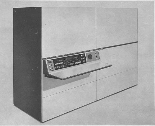 Photo by Advanced Scientific Instruments
APPLICATIONS
A general purpose digital computer flexible enough to satisfy both small
scale and medium scale computer needs. It is suitable for a wide variety
of applications, including those requiring on-line systems control.
Some applications are space-born vehicle simulation, nuclear research,
telemetry data reduction, missile design and analysis, reactor design and
simulation, radar control systems, statistical analysis, data acquisition
systems, trajectory computations, medical research, satellite computation,
data reduction systems, transformer design, automatic checkout systems,
communication switching systems, flight test data processing, aerial survey
data reductions, precision tracking of high-speed targets, flash
calculation, network analysis, and circuit analysis.
PROGRAMMING AND NUMERICAL SYSTEM
Automatic coding
Indirect addressing. Double precision arithmetic is automatic. There are 64
priority interrupt channels and automatic selection of three major levels
of program execution, facility for an unlimited number of external
devices, subroutine call instruction and instructions to facilitate
floating point operations.
There is a fully operable FORTRAN II Compiler. Programming system permits
use of combination of English words and mathematical language to express
a problem solution. The FORTRAN system translates statements to a
machine language object program, and the necessary data plus object program
are loaded into the computer for solution.
The Assembler II routine assembles four general categories of items: (1)
Machine instructions using mnemonic operation codes, (2) data, (3) macro
Photo by Advanced Scientific Instruments
APPLICATIONS
A general purpose digital computer flexible enough to satisfy both small
scale and medium scale computer needs. It is suitable for a wide variety
of applications, including those requiring on-line systems control.
Some applications are space-born vehicle simulation, nuclear research,
telemetry data reduction, missile design and analysis, reactor design and
simulation, radar control systems, statistical analysis, data acquisition
systems, trajectory computations, medical research, satellite computation,
data reduction systems, transformer design, automatic checkout systems,
communication switching systems, flight test data processing, aerial survey
data reductions, precision tracking of high-speed targets, flash
calculation, network analysis, and circuit analysis.
PROGRAMMING AND NUMERICAL SYSTEM
Automatic coding
Indirect addressing. Double precision arithmetic is automatic. There are 64
priority interrupt channels and automatic selection of three major levels
of program execution, facility for an unlimited number of external
devices, subroutine call instruction and instructions to facilitate
floating point operations.
There is a fully operable FORTRAN II Compiler. Programming system permits
use of combination of English words and mathematical language to express
a problem solution. The FORTRAN system translates statements to a
machine language object program, and the necessary data plus object program
are loaded into the computer for solution.
The Assembler II routine assembles four general categories of items: (1)
Machine instructions using mnemonic operation codes, (2) data, (3) macro
| BRL 1964, ASI 2100, starting page 0035
|
instructions, and (4) assembly control commands such as storage allocation
commands. It helps speed program preparation, simplifies program correcting,
segmenting and combining. Diagnostic and Service Routines. Program
selfchecking routines include:
  (1) A tracing routine for checking a known part of the program,
  (2) A routine to enable the programmer to dump or search selected
       portions of thememory,
  (3) Routines for loading and output operations for all forms of
        input/output equipment.
Subroutines. Floating point and mathematical function (Sine, Cosine,
Arctangent, Exponent, etc.) subroutines are furnished. Others, including
a decimal input and output routine, are available.

ARITHMETIC UNIT
                             Incl. Access
Operation Time               Microsec
Add, Single Precision          4
Multiply, Single Precision    30
Divide, Single Precision      44
Add, Double Precision         12
Load, Double Precision         8
Indirect Addressing            2
Jump                           2
Input/Output Cycle             2
Store and Logical Opn          4

STORAGE
                  No. of            No. of        Cycle
 Medium           Words             Bits/Word     Microsec
 Magnetic Core     4,096 - 32,768     21          2.0
 Magnetic Tape
Low, medium, and high density tapes that are IBM compatible.

INPUT
Medium                 Speed
Punched Cards          800, 200, or 100 cards/min
Magnetic Tape
Typewriter             Manual
Paper Tape             500 chars/sec
A 500,000 words/second input/output rate is provided by an assembly
register and interface control. There are
4 Input/Output channels. Independent and simultaneous operations of many
external devices are possible
because each device is provided with logic for sequencing its own control
and for communication with the central
computer. In addition, each device is provided with an independent program
interrupt system.

OUTPUT
Medium                     Speed
Punched Cards               250 or 100 cards/min
Line Printer (120 column)   400 lines/min
Magnetic Tape
Typewriter                   15 chars/sec
Incremental Plotter         300 steps/sec
 (11 in.wide, 0.005 in increment)
Paper Tape                  110 chars/sec

CIRCUIT ELEMENTS OF ENTIRE SYSTEM
All solid state pluggable printed circuit card construction
throughout with design for ready access to all circuits.
Standardization through reduced number of logic card types.

POWER, SPACE, WEIGHT, AND SITE PREPARATION
Power, computer         1.8 Kw
Volume, computer       67" x 25.5" x 76"
Air conditioner
 None required.
Weight, computer    1,200 lbs
Site preparation requirements
Standard 110/120 volt, 60 cycle/sec AC outlet required.
Air conditioner or humidity control is not required.

PRODUCTION RECORD
First Delivery, December 1963.

COST, PRICE AND RENTAL RATES
Price of computer begins at $87,800.
Monthly lease price $2,590.

PERSONNEL REQUIREMENTS
Training courses in 2100 programming and FORTRAN II are
available for customer programmers. In addition,
courses are offered for equipment operators and company
management. After installation, classes in advanced
systems are made available as well as a programmer's
workshop. These classes supplement the activities of the
ASI User's Group.

To expedite the interchange of information, ASI has
established a User's Group consisting of the following: A group
secretary to handle correspondence and coordinate group activities - a
regularlypublished Newsletter describing new software and hardware,
 a distribution center for the receipt, editing,
and distribution of software documentation on magnetic tape,
punched tape or cards.

ADDITIONAL FEATURES AND REMARKS
By pre-defining with a command the number of 6-bit characters
in a field, the assembly register will transmit to or
from memory a number of fields of data. Each field begins
with the most significant character of a word. Afield may
be 6 bits to 48 bits long allowing word length communication
compatibility with computers having word lengths
different than the 2100. The 2100 may communicate at the
rate of 1.75 million 6-bit characters/second. Any
channel may be connected to as many as 32 devices. Any one
device may be actively transmitting data at one
time with each channel.

Program can be automatically interrupted leading to a
distinct subroutine for each interrupt event. At the end of
each interrupt subroutine, control can be returned automatically
to the program at the point of interruption.

Provision for priority interrupt by external devices gives
three effective levels of program execution. Programmer
has complete program control over recognizing an interrupt
or ignoring a particular condition by selectively
arming and disarming interrupt traps.

The upright rack configuration of the 2100 makes it
particularly adaptable to laboratory or plant installations and
provides the necessary modularity for ease of expansion as computer
requirements increase.


Go To Table of Contents