This paper proposes a work-around for the missing connections in "our" RAMAC Track Position Potentiometer.
General problem - this potentiometer is highly specialized, having seven taps installed at rather precise locations.
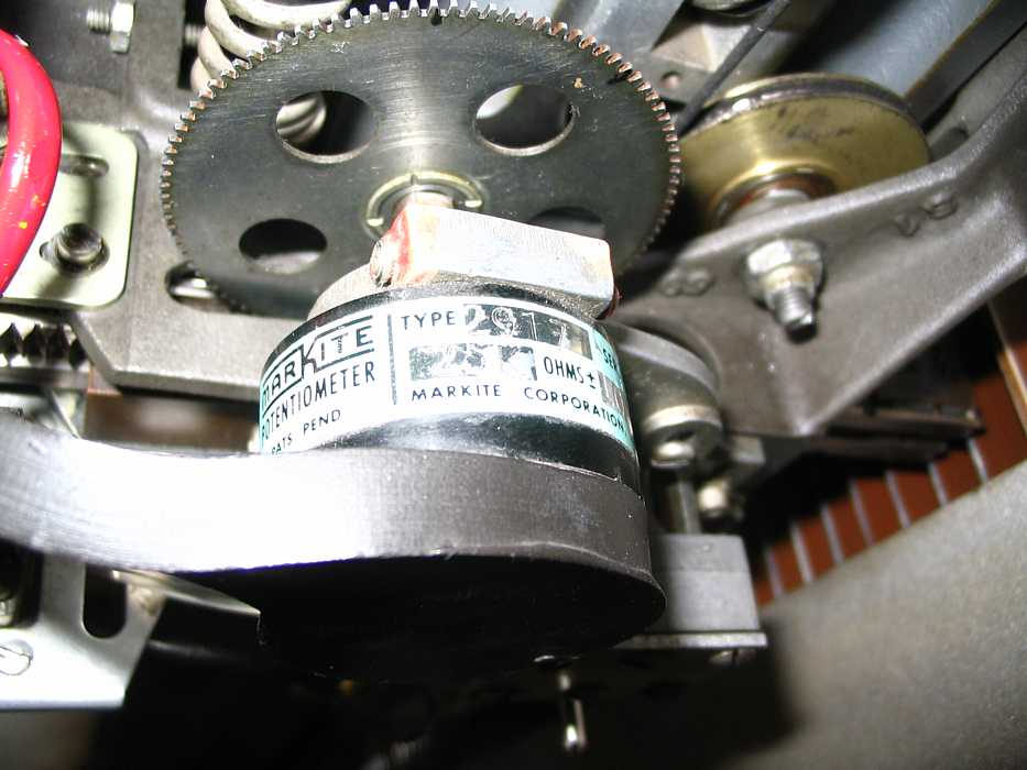
| This track position indication potentiometer has a problem. Two of the seven taps are open, and one end is open.
See here for further details.
|
 Proposal here
- From an Internet search, Markite was purchased by Litton was purchased by Northrop Grumman
- A search for "markite" and "potentiometer" came up with http://www.vsensors.com the name plate of Markite Potentiometers, Inc. - http://www.vsensors.com/rotary_pot.htm
- Contact Info is listed as
- 1-800-688-2181
- 2800 Anvil Street North, St. Petersburg, Fl. 33710
- (727 347-2181 (voice) - (727 347-7520 (fax)
- Would a deliberate Track Offset be useful?
Interesting speculation:- The Santa Clara University students noted here, page 22
"We found that pins one, three, and eight were not conduction. They are the points corresponding to the positive node, track 80, and track 100. In addition, we found that the gear that that moved the wiper on the potentiomenter has been offset by several teeth. This offset a track pin by approximately 2 tracks. For example, pin 4 originally had its origin at track 20 but today, because of the offset, pin 4 resides at approximately track 22."
Was this offset some past maintenance re-assembly error, or might it have been deliberate? for an effect?
I propose creating the error 2 tracks * in the other direction * which will allow proper servoing to the originally designed HOME position with our crippled position potentiometer.Consider:
- Use the student's technique of using the HOME pin as the + node. - (The next node is pin 7 - Track 00).
- You can now seek to the HOME node (using conventional set point servo techniques)
- (HOME position is now about two tracks inside of the old HOME tab.)
- The above scheme of offsetting the pot is useful in normal set point control.
All 100 user tracks can be accessed with set point servo control.
- Special switching would be required when using the original IBM servo method.
The above seems interesting to me. :-))
Ed Thelen - September 4, 2006
- A search for "markite" and "potentiometer" came up with http://www.vsensors.com the name plate of Markite Potentiometers, Inc. - http://www.vsensors.com/rotary_pot.htm
For another view, consider the following - added October 20, 2006
The IBM method of using the (good) Track Position Pot

As per
    http://www.ed-thelen.org/RAMAC/00Paper00Page21a-.jpg
connect pin ? (+ Node) to floating +
connect pin 5 (- Node) to floating -

if you want to go,    connect                      and
         Home            Pin 11 to ground
      tracks 00-20       Pins 7 & 4 to resistors;  connect appropriate resistor junction to ground
      tracks 20-40       Pins 4 & 10 to resistors;  connect appropriate resistor junction to ground
      tracks 40-60       Pins 10 & 6 to resistors;  connect appropriate resistor junction to ground
      tracks 60-80       Pins 6 & ? to resistors;  connect appropriate resistor junction to ground
      tracks 80-100      Pins ? & ? to resistors;  connect appropriate resistor junction to ground

and use the wiper, pin 2
    as per http://ed-thelen.org/RAMAC/SeniorMotionReport.pdf
page #28
   (Acrobat Reader has a search function - the binocular - and "wiper" is searchable )

as input to the position connection of the servo amplifier.
  (the other side of the differential servo amplifier is signal ground)


--------------------------------------

The student method of using the (partially defective) Track Position Pot
(the following is partly educated guesswork and osmosis from reading
   the student's report)
Since the + node is not connected,
   place positive reference voltage (say +5 volts) on the HOME Pin 11
      when trying to approximately position to home
            drive until the ADC is about +5 volts.

Make a table of head position # vs ADC reading from wiper, Pin 2
   for each track
for example
    track;   ADC reading (example)
     HOME      + 4.999
     00        + 4.804 volts
     01          4.776
     02          4.745
     03          4.716
...
     99          0.524
    100          0.492


-----------------------------------------

or make a suitable polynomial to adquately model the pot.
|
None of the above discusses the use of the tachometer,
Any servo text will give suitable detail.
If you have comments or suggestions, Send e-mail to Ed Thelen