Analog Discovery
my adventures with
Background
- Oscilloscopes can display fascinating voltage vs time pictures and also the phase relationship
between two voltages :-))
- In the Army, 1955, I bought and constructed a Heathkit 'scope that was advanced enough to display
the TV color-burst frequency
of 3.579545 MHz :-)) - probably a o-9 model - the ad said the color burst display was only 3 db down.
specifications,
schematic.
- The above disappeared in the intervening years - but I grew lonesome for another scope,
but by then Heathkit had disappeared and e-bay not yet invented.
- Then I occasionally bought a 'scope from flea markets - but the bulk of the needed accessories such as
signal generators, power supplies, drawers of components just didn't fit a family situation :-))
- While at Measurex I would occasionally borrow a company 'scope to help with a project, such as adding
added (dynamic ;-)) memory to the family PET computer.
- Much later I started looking at "USB oscilloscope" which are controlled and displayed by a PC
- but they seemed limited -
- Jan 2013 I noticed the
"Analog Discovery" unit by
Digilent which combines
oscilloscope, signal generator, digital I/O, and +- 5 volt power :-))
- I down loaded their Analog Discovery software package with reasonable user interface.
The demo mode seem flexible and well worked out -
So I ordered the Analog Discovery kit along with their
"Analog Parts Kit" without examining possible competitive offerings from others.
|
Table of Contents
The surprisingly small package arrives :-))
What do we have here??
Documentation
|
One greeting card sized cardboard saying buy AnalogDiscovery
and giving the URL to the web site.
There are five YouTube videos for training,
[ see Training below ]
so the lack of a
big heavy manual is not a hindrance - a person would really not use it,
much preferring to use the convenient on-line material instead !!
|
AnalogDiscovery
|
A neat little storage box with device and USB cable. I plugged it into my PC - the software recognized
the device immediately, and the device signal generator sent the commanded tones to my now plugged-in
ear phones - GREAT, no muss, no fuss :-))
Loopback is accomplished with supplied male-male connectors, and using the instructions in
here was able to view the signal
generator output with the oscilloscope :-)) - GREAT, no muss, no fuss :-))
|
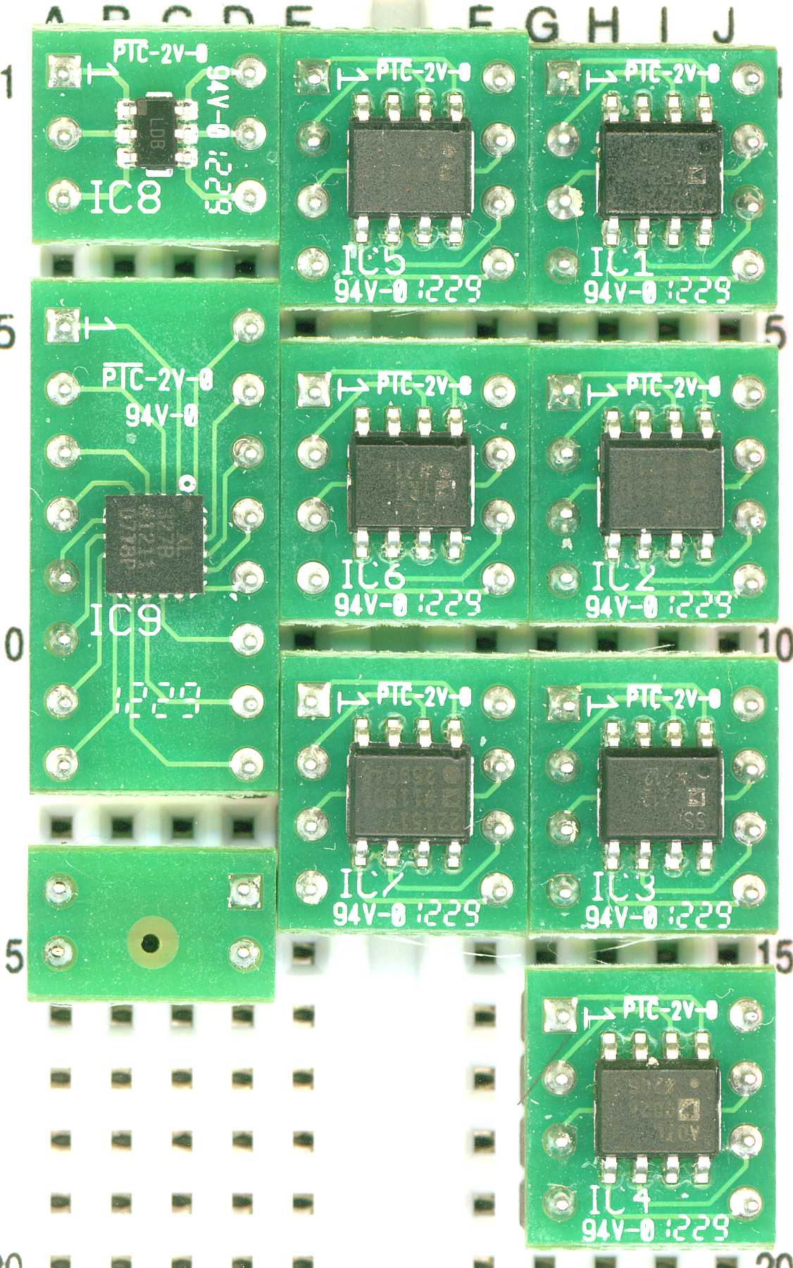
Analog Parts Kit
|
Looks nice and neat, such tiny components, a number of DIP packages, but the rest
is very much smaller since the 1970s, see below. I feel very out of date.
|
Mini "Grabber" test clips
|
How to connect probes to them to the AnalogDiscovery is on the web site link above -
|
|
Training
I put Training here because with out that on-line aid - I was helpless -
There are five Analog Discovery training video series on YouTube,
starting here.
Currently, YouTube gives a thumb-nail of the next in the series in the upper right hand
corner of your monitor. Clicking there will start the next in the series :-))
The very good instructor assumes that
you have the "Analog Parts Kit", or an extensive electronics warehouse.
I feel very lucky to have purchased the "Analog Parts Kit" with the order.
The first project in the training is to wire up (on the little plugboard) a blinking LED
in series with a resistor - (really needed or you smoke the LED, which is extremely voltage sensitive.)
I quickly learned that there is over-current detection in the AnalogDiscovery which shuts down
all outputs and gives a warning box on the monitor. Gads - my bad wiring, try again. Gads, now what ??
After some fumbling about I find that I have set a +5 volt offset into the Signal Generator,
and that 5 volts plus the AC output I set caused this over-current situation - removed the +5 volt
offset, and every thing worked as suggested in the video.
There are five YouTube videos for AnalogDiscovery:
- Getting Started - Quickstart #1 -
https://www.youtube.com/watch?v=aYgFKIsrOYQ
- Voltage Tool - Quickstart #2 -
https://www.youtube.com/watch?v=Gdl7hPFaPWI
- Voltmeter - Quickstart #3 -
https://www.youtube.com/watch?v=Va1lURqbmew
- Arbitrary Waveform Generator - Quickstart #4 -
https://www.youtube.com/watch?v=rXJXphcV1Vk
The Arbitrary Waveform Generator has many functions, this is a good start -
- Oscilloscope - Quickstart #5: -
https://www.youtube.com/watch?v=pmJzBCv5G2g
Any flexible oscilloscope, and this is indeed!! is almost a study in itself !!
- Many new concepts and functions !! - This is just a good working start !!
- A full treatment with exercises would be several days of serious study
Please note: after an initial introduction to complex equipment such as the signal generator
and the 'scope above - most folks go into a period of trying out different options which might
be useful in different circumstances - Not advertized nor discussed in the videos, but interesting
to me were:
- X vs Y plotting for signal phase relationships
- FFT (
Fast Fourier Transform) computing and display
Both of which are also available in the package :-))
Both were fairly intuitive, try 'em out and see what happens, learn by doing - that seems the modern way
for our very complex world -

|
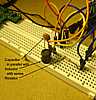
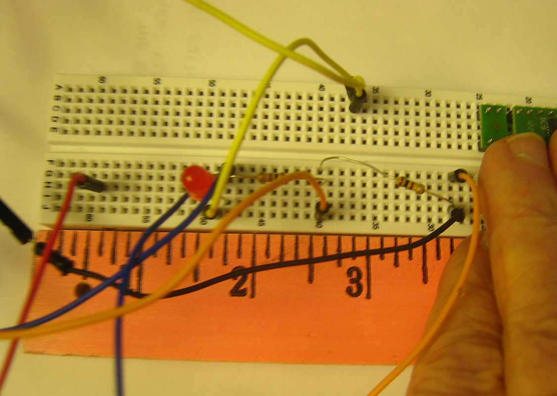
Here is the little LED and resistor circuit built up and used in the above lessons.
|

|
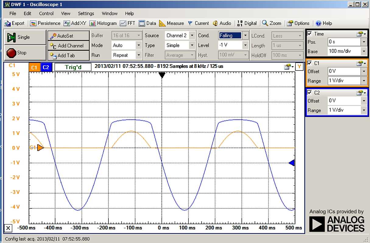
And this is the dual trace oscilloscope view of the proceedings.
- blue trace - voltage across the LED
- orange trace - current through LED
|
|
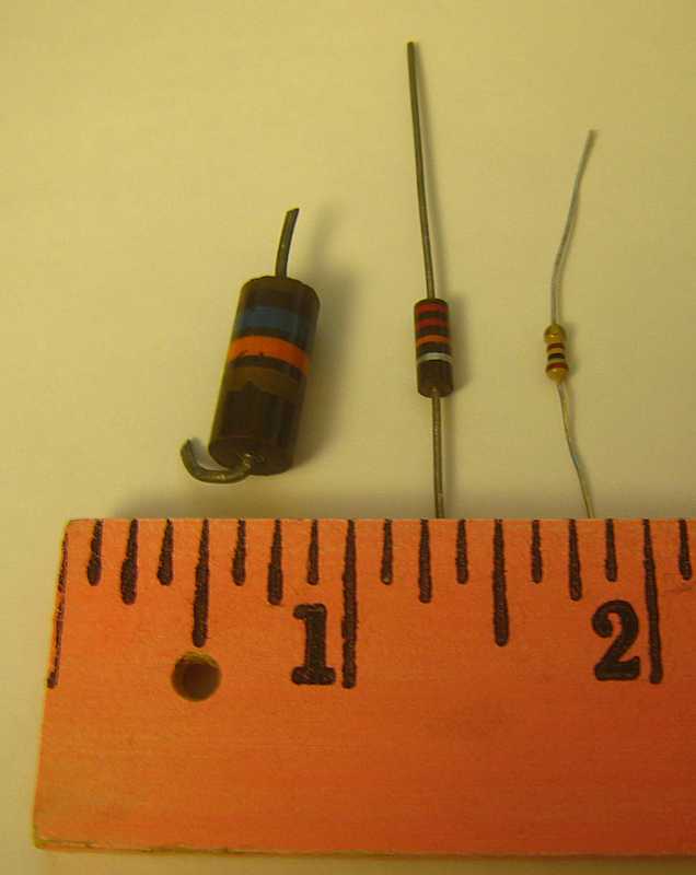
Components
I found identifying components "interesting"
The good news:
Suggestions:
- A little sheet of component codes would be nice.
I didn't remember the 3 digit capacitor codes,
104 is 0.1 ufd, 102 is 0.001 ufd,
is useful
- A good magnifying lens is likely necessary for most people
The bad news:
|
Some fun with the 'scope
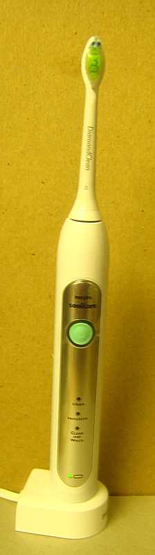
We have electric tooth brushes in our house - supposed to be very good.
A question - the base is plugged in, and the battery/motor/brush assembly
sits on the base to charge the battery - but there is no exposed copper conductor
visible to conduct the electric energy.
How does the energy get from the base to the battery???

| Here is an electric toothbrush with its charging base.
|

| Here is the charging base, no contacts, with an inductor as a sensor,
connected to the Digilent "Oscilloscope".
|

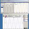
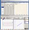
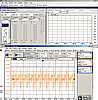
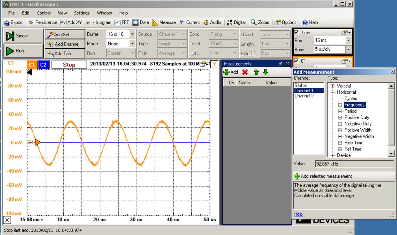
| Here is the Digilent "Oscilloscope" as seen on my monitor :-))
- We have set up a single scan, the vertical gain and horizontal timing is plain to see.
- We have also set up a horizontal measurement, lower right, selecting "Frequency"
- Note the frequency 92.657 kHz, and the method -
|
How is that for cute and handy ;-))
The base continuously oscillates at about 100 kHz, and when the
toothbrush sits on it, that energy couples into a coil of the toothbrush
and charges the battery :-))
|
Parallel Resonance
Learning electronics, after DC theory and circuits, not very dynamic, hopefully -
usually AC theory and circuits is taught, life gets "interesting" !!
Skipping series RC and RL circuits as lessons in phase shifting,
we come to parallel resonant circuits, and life gets more interesting :-))
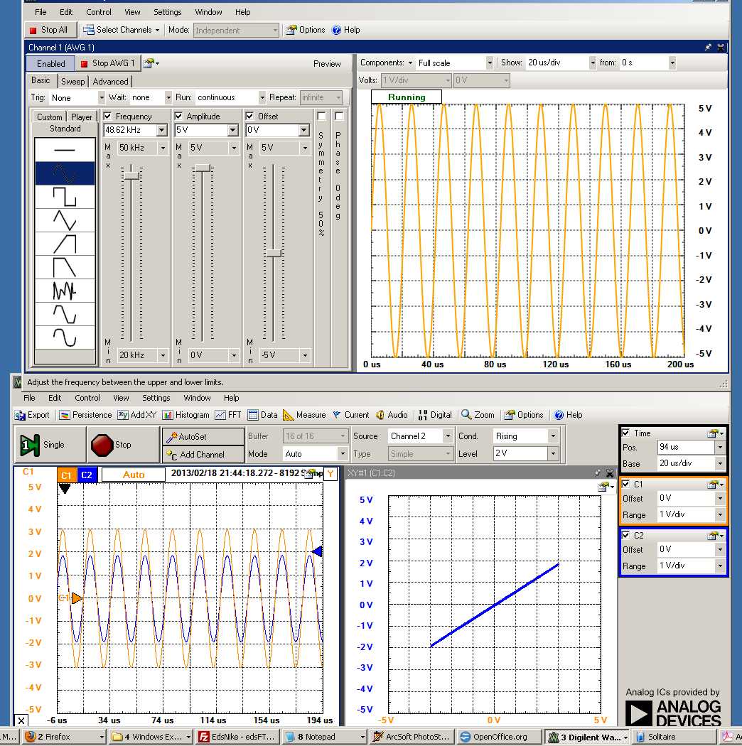
| So, here we are all connected up with AC source across everything and
voltage sensing across the parallel circuit and across the resistor :-))
|
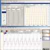
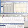
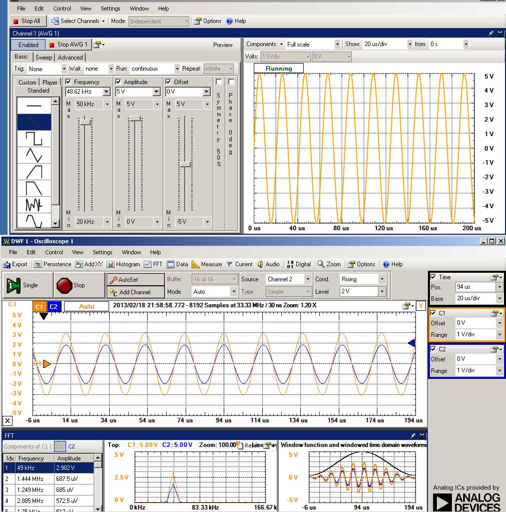
And the wave forms :-))
Orange is voltage across the resonant circuit, Blue is voltage across the resistor
Note the different phase shifts :-))
| A little off resonance, 40.35 kHz
| 
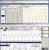
| Just about on resonance, 48.5 kHz
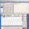
| Buildup of oscillations with start of excitation
| 
| Showing XY at about resonance, 48.5 kHz
| FFT w Hamming window w constant excitation
| 
| Using triangle wave for excitation, note that there is very little harmonic power
across the resonant circuit - the orange line -
| | |
|
Trying the Microphone
|
Lets try the enclosed microphone, IC10 - ADMP504, and show the wife some natural wave forms :-))
The
Analog Parts Kit links to the data sheet which says that it required 3.3 volts power -
our ANALOG DISCOVERY regular power is +- 5 volts. We have a choice:
- a) use IC8 for 3.3 volts
- b) use the Signal Generator to provide the 3.3 volts
Choosing simplicity, lets use the Signal Generator, and watch its voltage for sag.
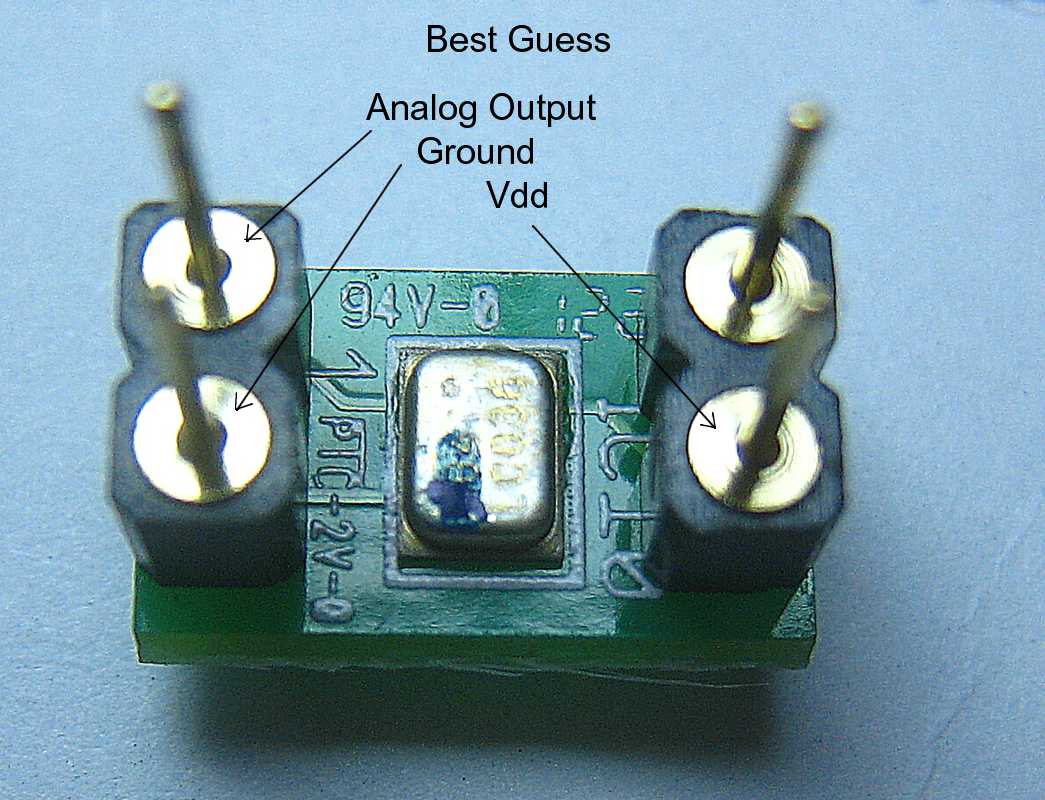
Now to the microphone, I printed out the linked Data Sheet for the ADMP504
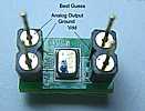
| I turn the carrier over, I can see an alignment dot - OK - an ink mark -
no, I don't think so - I bet it is the other end -
The pictured configuration works :-))
|
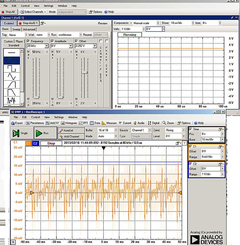
So, lets wire it up and set it up
|
The 3.3 volts from the Signal Generator is applied to power the IC-10
Well, the output has a bias of about +0.8 volts and little amplitude -
- So I put a small capacitor between the output stage and the oscilloscope
- Set gain to 5 mVolts/vertical division,
say "AH" into the microphone for the doctor, and look at that :-))
|
|
Handy Component Codes
from USAF-RadarStationVeterans@yahoogroups.com
Posted by: "Jim Sanders" anfps26
| 0 | 1 | 2 | 3 | 4 | 5 | 6 | 7 | 8 | 9 | . | . | .
| | Bad | Boys | Rape | Our | Young | Girls | But | Violet
| Goes | Willingly | Get | Some | Now.
|
 Resistor Color Code - from http://itll.colorado.edu/images/uploads/resistorchart.jpg Resistor Color Code - from http://itll.colorado.edu/images/uploads/resistorchart.jpg
|
That's all for now folks -
Updated through February 21, 2013


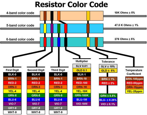 Resistor Color Code